
S82 W18717 Gemini Drive
Muskego, Wisconsin 53150
Phone: (877) 622-2694
Fax: (888) 679-3319
www.nabcoentrances.com
Technical Support: (866) 622-8325
Part #C-00084
Rev. 9/09/16
WARNING
• Turn OFF all power to the Automac Door if a Safety System is not working.
• Instruct the Owner to keep all power turned OFF unl correcve acon can be achieved by a NABCO
trained technician. Failure to follow these pracces may result in serious consequences.
• NEVER leave a Door operang without all Safety detecon systems operaonal.
Swing Door Operator
Wiring and Adjustment Manual
** with Magnum 4A Control*
DN 0557
LED
TRANSFORMER
AUX
PWR
J2
J5
AC IN
SW2
SW1
F1
RELAY
RELAY
J4
TDAS
SIGNAL
INPUT
TDPG
LCHK
CLOSE
Fuse 1: 0.5A 24 VAC
STOP
OPEN
BCHK
CURRENT
LIMIT
MOTOR
J1
R28
MAGNUM 4A
F2
Fuse 2: 5
A
120/240
Capacitor
MO
V
1234O
F
F

i
Rev. 9-09-16 Part #C-00084
www.NabcoEntrances.com Magnum 4A Control Wiring and Adjustment Manual
Table of Contents
Warning Labels .................................................................... ii
General Safety Recommendaons ....................................................iii
.......................................................
Secon 1a. To the Installer ...............................................................1-4
Secon 1b. Objecve ...................................................................1-4
............................................
Secon 2a. Features: ....................................................................2-5
Secon 2b. Electrical Specicaons ........................................................2-5
Secon 2c. Output Power Guidelines ......................................................2-6
..............................
Secon 3a. Main Harness ................................................................3-7
Secon 3b. Power Harness ...............................................................3-8
Secon 3c. Motor Harness (300/400/500) ..................................................3-9
Secon 3d. Motor Harness (710/8310/8710) ................................................3-9
Secon 3e. Fuses .......................................................................3-9
.............................
Secon 4a. Swing Door Posions .........................................................4-10
Secon 4b. Adjustments ................................................................4-10
Secon 4c. Status LEDs .................................................................4-14
.........................
....................................
Secon 6a. Panic Breakout Latch/Switch (Open Loop Connuous Safety Circuit) ..................6-16
Secon 6b. Panic Breakout Latch/Switch (Closed Loop Connuous Safety Circuit) .................6-17
...............................
Secon 7a. GT-300-400-500 Single Door ...................................................7-19
Secon 7b. GT-300-400-500 (Simultaneous Pair) ............................................7-20
Secon 7c. GT-300-400-500 (Simultaneous Pair w/One Magnum 4A Control) ....................7-21
Secon 7d. GT-710-8310-8710 Single Door ................................................7-22
Secon 7e. GT-710-8310-8710 (Simultaneous Pair) ..........................................7-23
Secon 7f. GT-710-8310-8710 (Simultaneous Pair w/One Magnum 4A Control) ..................7-24
Secon 7g. GT-1400 Single Fold with One Magnum 4A Control ................................7-25
Secon 7h. GT-1400 Bi-Fold with Two Magnum 4A Controls ..................................7-26
Secon 7i. GT-1400 Bi-Fold with One Magnum 4A Control ....................................7-27
...........................
Secon 8a. Transformer Installaon and Wiring for 240 Volts .................................8-28
........................................

ii
Magnum 4A Control Wiring and Adjustment Manual www.NabcoEntrances.com
Part #C-00084 Rev. 9-09-16
WARNING LABELS
Warning labels are universal and used to alert an individual of potential harm to one’s self or to others. The following warning
labels are listed in a hierarchy order that denes the most potential danger rst, and the least potential danger last. Please refer
to this page in the event that a warning label is displayed within this manual and further denition needs to be explained.
high
some
is present.
may result in a minor injury
DANGER
WARNING
CAUTION

iii
Rev. 9-09-16 Part #C-00084
www.NabcoEntrances.com Magnum 4A Control Wiring and Adjustment Manual
GENERAL SAFETY RECOMMENDATIONS
Header.
WARNING
DANGER
CAUTION
DANGER
CAUTION
CAUTION
CAUTION

1-4 Scope
Magnum 4A Control Wiring and Adjustment Manual www.NabcoEntrances.com
Part #C-00084 Rev. 9-09-16
The purpose of this manual is to familiarize the installer with the proper installation and operation of this
system. It is essential that this equipment be properly installed and operational before the door is used
by the public. It is the installer’s responsibility to inspect the operation of the entrance system to be sure
it complies with any applicable standards. In the United States, ANSI Standard 156.10 (Used to cover Full
Energy doors) and ANSI Standard 156.19 (Used to cover Low Energy doors) apply. Other local standards
or codes may apply. Use them in addition to the ANSI standards.
The owner should determine the door is operating properly and should immediately call for service if
trained technicians.
X New or Existing Swing Door systems.
X New or Existing Fold Door systems
X
This manual offers step by step instructions.

Rev. 9-09-16 Part #C-00084
www.NabcoEntrances.com Magnum 4A Control Wiring and Adjustment Manual
Geng Started 2-5
►
► Replaces all Magnum controls.
► Replaces the analog swing control (requires two controls for sim pair installations).
►
►
► Digital parameter settings for repeatability.
►
controls required for sim pair and bifold applications).
►
►
►
encoder motor.
►
►
► Two transistor outputs with programmable functionality for air curtains or other devices.
►
► Recycle on object detection during Opening cycle with all motors.
►
► Full Power or Low Energy application capability.
►
might be commonly used. Onsite wiring may be different from that shown.
Table 2-1 Sensors
Sensor Part Number Function Power Source Current Consumption
Acuvision Infrared
Acuwave Infrared
Infrared
Infrared
Table 2-2 Modules
Module Part Number Function Power Source Current Consumption
RF Signal Transmission 50mA
Multi Module Programmable Relay 40mA

Magnum 4A Control Wiring and Adjustment Manual www.NabcoEntrances.com
Part #C-00084 Rev. 9-09-16
2-6 Geng Started
Table 2-3 Power Wiring
Wiring Power Current Consumption
Maximum Input 500mA (0.5amps)
Output (Available for Accessories) 500mA (0.5amps)
Available Wire Size for Incoming Power 14 AWG -
-
-
Fuses -
-
► Sensors
► Modules
► Accessories
► Auxiliary Equipment
If current draw exceeds 500 mA (0.5 amps) the installer must utilize an auxiliary power supply
such as the
The Opus 10 Control must Not be used to output power to:
► Magnetic Locks
► Electric Strikes
To determine if an auxiliary power supply must be used, add the total current draw of all devices. Please
50 mA
An Auxiliary Power Supply does not need to be used.
CAUTION

Rev. 9-09-16 Part #C-00084
www.NabcoEntrances.com Magnum 4A Control Wiring and Adjustment Manual
Magnum 4A Board Terminals 3-7
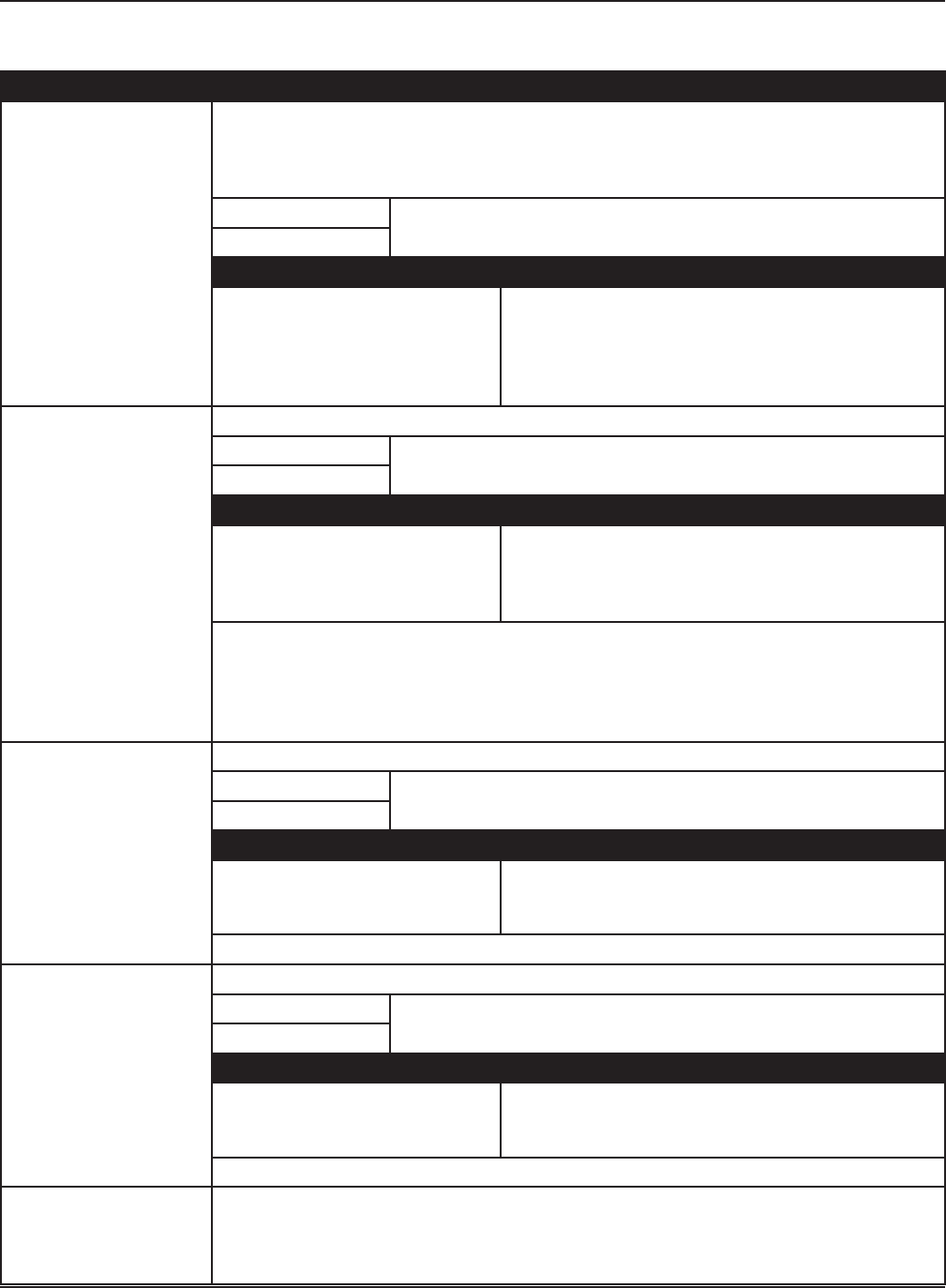
.
Figure 3-1
DN 0596
F1
J2
J4
J5
J1
Terminal Connector Harness
J1 Input Signal Main
J2 Auxiliary Power Main
J4 Incoming PowerPower
J5 Motor Motor
F1 Rese able Fuse
Non-Replaceable
N/A
F2 Not Rese ableFuse N/A
LED
TRANSFORMER
AUX
PWR
J2
O
F
F
12 4
3
J5
AC IN
SW2
SW1
F1
RELAY
RELAY
J4
TDAS
SIGNAL
INPUT
TDPG
LCHK
CLOSE
Fuse 1: 0.5A 24 VAC
STOP
OPEN
BCHK
CURRENT
LIMIT
MOTOR
J1
R28
MAGNUM 4A
F2
Fuse 2: 5
A
120/240
Capacitor
MO
V
F2
Main Harness
►
►
Please see .
Figure 3-2
DN 0588
1
2
3
4
5
6
3
2
1
2
1
5
4
6
1
2
3
4
Brown
Orange
Violet
White
Red
Black
Orange
Blue
Red
Signal Input Harness to Connector J1
Auxiliary Power Harness to
Connector J2
Switch Harness
(to operator posion switches)
6 Pole Terminal Block
connected.

Magnum 4A Control Wiring and Adjustment Manual www.NabcoEntrances.com
Part #C-00084 Rev. 9-09-16
3-8 Magnum 4A Board Terminals
Table #-1
Pole Wire Harness Circuit Description
1 Aux Pwr X
X Sensor must not exceed 0.5 amp current draw.
X If Sensor exceeds 0.5 amp current draw Fuse (F1) will trip. A
separate power supply must be used.
Orange
Terminal X
X
• Stop door during opening
• Prevent door from moving when door is fully closed
X
4 White X
on pull side of door.
X
• Prevent door from opening if already closed
•
X
5 Red
6 Activation
door is activated.
Table #-2
Pin Wire Circuit Description
1 Orange
Red
4
Power Harness
.
Figure 3-3
DN 0606
1
Table #-3
Pin Wire Circuit Description
1 Green Incoming Ground wire
White Incoming Neutral wire

Rev. 9-09-16 Part #C-00084
www.NabcoEntrances.com Magnum 4A Control Wiring and Adjustment Manual
Magnum 4A Board Terminals 3-9
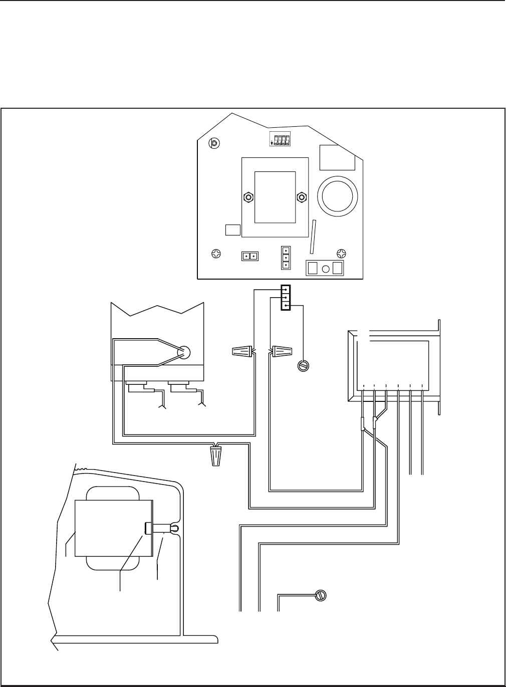
Motor Harness
Figure 3-4
DN 0559
(J5) Motor Connector
Brake Module Connector
plugs into J5
Motor Brake Module
Motor Leads
LED
TRANSFORMER
AUX
PWR
J2
J5
AC IN
F2
SW2
SW1
F1
RELAY
RELAY
J4
TDAS
SIGNAL
INPUT
TDPG
LCHK
CLOSE
Fuse 1: 0.5A 24 VAC
STOP
OPEN
BCHK
CURRENT
LIMIT
MOTOR
J1
R28
MAGNUM 4A
Fuse 2: 5A 120/240
Capacitor
MOV
O
F
F
12 4
3
X
X
Figure 3-5
DN 0597
Connector plugs
into (J5)
Motor Leads
Motor Input
(J5) Motor Connector
LED
TRANSFORMER
AUX
PWR
J2
O
F
F
12 4
3
J5
AC IN
SW2
SW1
F1
RELAY
RELAY
J4
TDAS
SIGNAL
INPUT
TDPG
LCHK
CLOSE
Fuse 1: 0.5A 24 VAC
STOP
OPEN
BCHK
CURRENT
LIMIT
MOTOR
J1
R28
MAGNUM 4A
F2
Fuse 2: 5
A
120/240
Capacitor
MO
V
Fuse Amp Usage Description
F1 .5 Resettable X
X Protects
5 Not Resettable

4-10 Adjustments and Status LEDs
Magnum 4A Control Wiring and Adjustment Manual www.NabcoEntrances.com
Part #C-00084 Rev. 9-09-16
Do Not touch other parts of the Magnum 4A Control board with a screwdriver or
anything else metal. Damage to electrical circuitry may occur.
Figure 4-1 Door Positions
DN 0035
Back
Check
Latch
Check
Main Speed
Door Cycle
Closed
Position
Description
Opening
Range from fully closed to 10° from fully open.
10° from fully open to fully open.
Range from fully open to 10° from fully closed.
10° from fully closed to fully closed.
Adjustments
DN 0560
Adjustment Poten ometers
Dip Switch (SW1)
SW2
R2
R3
R4
R5 R6
R7
R8
TDAS TDPG LCHK
CLOSESTOP OPEN
BCHK
CURRENT
LIMIT
R28
LED
O
F
F
12 4
3
SW1
Slide Switch (SW2)
.
CAUTION
Figure 4-2 Adjustment Locations

Adjustments and Status LEDs 4-11
Rev. 9-09-16 Part #C-00084
www.NabcoEntrances.com Magnum 4A Control Wiring and Adjustment Manual
Figure 4-3 Dip Switch (Displayed in ON position)
DN 0561
OFF
SWITCHES SHOWN IN “ON” POSITION
1 Not Used
2 OFF: Closed Loop Safety / ON: Open Loop Safety
3 OFF: Push-N-Go active / ON: Push-N-Go Inactive
4 OFF: Sequential Mode / ON: Timer Mode
Table 4-1 Dip Switch Settings
Switch Adjustment
1 Not Used
On Open Loop Safety X Safety triggered when contact is closed by a Switch or Sensor
Off X * Safety triggered when contact is opened by a Switch or Sensor
On X
Off X
active in any position.
X
X Door opens when pushed.
• Switch 4 must be turned “On” for door to time out and close.
4 On Timer Mode X Door will open, time out and then close.
Off Sequential Mode X One activation opens door, second activation closes door.
► Upper Position
• Used for Low Energy Operators.
• Motor power is reduced to approximate ANSI 156.19 Low Energy Standards.
► Lower Position
• Used for Standard Full Automatic Operators.
•
• Motor power is increased to approximate ANSI 156.10 Standards.
It is recommended to set door speeds as slow as the owner will accept, and no more than the applicable
ANSI Standards. Use a stopwatch for assistance. Please see .
► a parameter.
► a parameter.

4-12 Adjustments and Status LEDs
Magnum 4A Control Wiring and Adjustment Manual www.NabcoEntrances.com
Part #C-00084 Rev. 9-09-16
point. Potentiometer settings might need to be adjusted accordingly. After each adjustment, wait at least 5
seconds before testing.
All electrical troubleshooting or service must be performed by trained, qualied
technicians and comply with all applicable governing agency codes.
Table 4-2 Potentiometers
Potentiometer Description
Stop X Stops or slows door when object is detected in path of opening door (not yet in
X
•
•
X Also adjusts the power to the motor when the door is held open for extended periods
the motor overheating at hold open allowing the door to close as well as reducing
stress on mechanical and electrical components. To adjust power applied to the door
be reduced according to the “STOP” setting. If the door begins to slowly drift close
full open position. Door should hold open and not drift close.
If door still drifts close, continue increasing STOP power until the door holds
open against the door stop.
Each time an adjustment is made, the door must be allowed to close, and then
Event Action
Object is detected in path of
opening door by Door Mounted
Sensor that is mounted on swing
side of door and connected to
X
X
X
Open Sets opening speed of door.
Event Action
Door opened at wrong speed. X
X
X
Event Action
adjustment.
X
X
X
CAUTION
Adjustments and Status LEDs 4-13
Rev. 9-09-16 Part #C-00084
www.NabcoEntrances.com Magnum 4A Control Wiring and Adjustment Manual
Potentiometer Description
TDAS
(Time Delay Activating Signal)
Determines how long door will stay open after activation (or input signal) is released.
and
Full Automatic door
Low Energy door
Event Action
adjustment.
X
X
X
X
stay open.
TDPG
Full Automatic door
Low Energy door
Event Action (Full Automatic doors)
adjustment after door is pushed.
X
X
X
stay open.
X
operators that use a clutch gear, Push n Go is only active from the fully closed position
once the door is manually pushed out of latch position.
X If Push n Go is desired for all door positions, a clutchless operator must be ordered.
(Not used on
Full Automatic door
Low Energy door
Event Action
adjustment.
X
X
X
(Not used on
Full Automatic door
Low Energy door
Event Action
adjustment.
X
X
X
Adjusts how hard the door will push against an obstacle (while opening) before recycling.
X
X
adjustments are made to the door and door operation is satisfactory.

4-14 Adjustments and Status LEDs
Magnum 4A Control Wiring and Adjustment Manual www.NabcoEntrances.com
Part #C-00084 Rev. 9-09-16
Potentiometer Description
Event Action
Recycle sensitivity needs
adjusting.
X
until all other adjustments
are made.
X When recycle is triggered, door will stop and
coast to a close. Wait at least (5) seconds before
Reactivating.
X
X
• Decreased Recycle Sensitivity.
X
• Increased Recycle Sensitivity.
X
adjusted according to door weight and speed.
X
stop door from opening.
at any instant within
the Swing door cycle. This helps to identify when the Swing door system is functioning properly. Please
see .
Figure 4-4 LED Indicators
DN 0558
Red LED
Green LED
LED
TRANSFORMER
AUX
PWR
J2
F1
TDAS
SIGNAL
INPUT
TDPG
LCHK
CLOSE
Fuse 1: 0.5A 24 VAC
STOP
OPEN
BCHK
J1
Table 4-3 Status LED Indicators
LED Status Description
Green Indicates door position during an open and closed cycle.
Indicator Action
Fast Flashing Door is opening.
On Solid
Slow Flashing Door is closing.
Off
Red Safety
Swing door cycle.
Indicator Action
Slow Flashing X Door mounted Sensor on Swing side of door is activated.
X
Fast Flashing X
activated.
X
On Solid X

Connect Incoming 120 VAC Wires 5-15
Rev. 9-09-16 Part #C-00084
www.NabcoEntrances.com Magnum 4A Control Wiring and Adjustment Manual
Disconnect 120 VAC power prior to making any electrical connections. Failure to
do so may result in serious personal or fatal injury. When uncertain whether power
supply is disconnected, always verify using a voltmeter.
Notice: Wiring must meet all local, state, federal or other governing agency codes.
Ensure all power is disconnected.
All high voltage electrical connections must be made by licensed electricians.
a.
Keep all Incoming 120 VAC wiring separate from low voltage wiring within Header.
a.
DANGER
CAUTION
6-16 Wiring Safety Devices
Magnum 4A Control Wiring and Adjustment Manual www.NabcoEntrances.com
Part #C-00084 Rev. 9-09-16
Do Not touch other parts of the Magnum 4A Control board with a screwdriver or
anything else metal. Damage to electrical circuitry may occur.
feature and disable the Operator.
Turn OFF Power.
.
DN 0060
EXT
INTERIOR SIDE
EXTERIOR SIDE
Figure 6-1
.
Figure 6-2
DN 0061
Connects to
Panic Breakout Limit Switch
Brown
Black
Brown
Black
.
CAUTION

Wiring Safety Devices 6-17
Rev. 9-09-16 Part #C-00084
www.NabcoEntrances.com Magnum 4A Control Wiring and Adjustment Manual
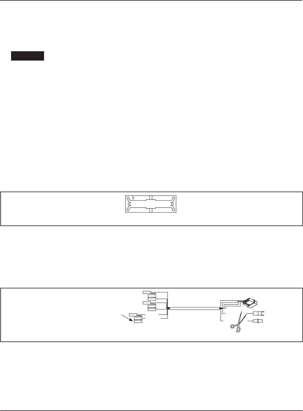
Figure 6-3 Wire Panic Latch for Full Automatic doors
DN 0566D
Part # 22-10065
Harness Assy
for Single
Part # 12-13166
Motor Fuse
(GT300, 400, 500)
Panic Latch must be flipped.
Arrow marked "EXT" must
point to the Interior of
building.
(Contacts must close
when door is broken out)
Back Check Limit Switch
(Black and Brown)
Breakout Limit Switch: N.O.
Terminals 3 and 5
MUST be connected to Continuous Safety input,
Breakout Limit Switch Signal and Panic Latch Signal
When the unit has Panic Breakout feature,
Panic Latch Kit
Part # 11- 0941
Red
Red
Brown
Black
Red: Comm, Blue: N.C.
for Magnum Board
300/400/500 Harness
Part # 21-9934
BROWN
BLACK
RED
WHITE
VIOLET
ORANGE
Operator Assembly
USE THESE CONNECTIONS ON INSWING
DOORS WITH PANIC BREAKOUT
1
6 3
5
4
2
LED
TRANSFORMER
O
F
F
12
AU
X
PWR
4
J2
3
J5
AC IN
F2
SW
2
SW
1
F1
RELAY
RELAY
J4
TDAS
SIGNAL
INPU
T
TDPG
LCHK
CLOS
E
Fuse 1: 0.5
A 24 VA
C
STOP
OPEN
BCHK
CURRENT
LIMIT
MOTO
J1
R2
8
MAGNUM 4A
R
Fuse 2: 5
A
120/240
Capacitor
MO
V
Please see .
Figure 6-4
DN 0565
EXT
.
The new “Fail Safe” safety circuit feature on the Magnum control is only available on recent controls as

6-18 Wiring Safety Devices
Magnum 4A Control Wiring and Adjustment Manual www.NabcoEntrances.com
Part #C-00084 Rev. 9-09-16
Turn OFF Power.
arrow points to the Exterior
.
DN 0644
EXT
INTERIOR SIDEEXTERIOR SIDE
Figure 6-5
Please see .
.
Figure 6-6 Panic Latch (Fail Safe)
DN 0570
BROWN
BLACK
RED
WHITE
VIOLET
ORANGE
23456 12356
To Magnum Control
Safety with Lockout
during door swing
To Terminal #5
Normally Closed Contacts
Continuous Safety
Normally Closed Contacts
Red
Red
Part # 11- 0941
Panic Latch Kit
TERMINAL BLOCK
#1 BROWN
#2 ORANGE
#3 VIOLET
#4 WHITE
#5 RED
#6 BLACK
24VAC NEUTRAL
24VAC HOT
CONTINUOUS SAFETY
SAFETY WITH LOCKOUT
ACTIVATION
When using normally closed safety, all panic breakout devices connected to
continuous safety must be wired in series. If sensor contacts
or a panic latch opens, the door can not activate.
BROWN
BLACK
RED
WHITE
VIOLET
ORANGE
23456 1234
To Magnum Control
Safety with Lockout
To Terminal #5
Normally Closed Contacts
Continuous Safety
Normally Closed Contacts
Red
Red
RedRed
SIMULTANEOUS PAIRS
SINGLE DOORS
Panic Latch must be positioned so that
arrow marked "EXT" points to exterior of building.
(Contacts must open when door is broken out)
Panic Latch must be positioned so that
arrow marked “EXT” points to exterior of building.
(Contacts must open when door is broken out)
Safety with Lockout
(Overhead Sensors)
Normally Closed Contacts
On double egress doors
using two overhead safety
sensors with normally closed
safety, outputs of both
sensors must be wired in
series.
(Overhead Sensor)( Door Mounted Sensor)
Continuous Safety
Normally Closed Contacts
(Door Mounted Sensor)
To Terminals
4 and 5
COMMON

Wiring Diagrams (General) 7-19
Rev. 9-09-16 Part #C-00084
www.NabcoEntrances.com Magnum 4A Control Wiring and Adjustment Manual
DN 0567
Off
H
o
l
d
O
p
e
n
O
n
Off
White
Black
Red
Activation
Safety with Lockout
during door swing
Continuous Safety
24 VAC AUX Output
for sensors
TERMINAL BLOCK
#1 BROWN
#2 ORANGE
#3 VIOLET
#4 WHITE
#5 RED
#6 BLACK
24VAC NEUTRAL
24VAC HOT
CONTINUOUS SAFETY
SAFETY WITH LOCKOUT
24VAC COMMON
ACTIVATION
Ground
Black(Hot)
Black
Black
White (Neutral)
Part # 21-9934
300/400/500 Harness
for Magnum Board
Red: Comm, Blue: N.C.
White: Comm, Green: N.
C.
Black
Brown
Common
N.O.
Device
Not Used
Typical
Mat or
Wall Switch
24 VAC
Input
Typical Sensor
Device
If Rocker Switch is not Required
Connect the Activation Signals to
Terminals 5 and 6 Directly
Part # 10-3528
RS-12 Rocker Switch
Red
Red
Part # 11- 0941
Panic Latch Kit
When the unit has Panic Breakout feature,
Breakout Limit Switch Signal and/or Panic Latch Signal
MUST be connected to Continuous Safety input,
Terminal Block #3 
Breakout Limit Switch: N.O.
(Black and Brown)
Latch Check Limit Swit
ch
Part # 22-10065
Harness Assy
for Single
Back Check Limit Switch
BROWN
BLACK
RED
WHITE
VIOLET
ORANGE
Ter
#5
to Te rminal
#5 (red)
to Te rminal
#5 (red)
to Te rminal
#5 (red)
to Te rminal
#5 (red)
to Te rminal
#5 (red)
Panic Latch must be flipped.
arrow marked "EXT" points into the building.
(Contacts must close when door is broken out)
to Te rminal
#5 (red)
123456
ON/OFF
ROCKER
SWITCH
120 VAC
Part # 12-13166
Motor Fuse
(GT300, 400, 500)
LED
TRANSFORMER
O
F
F
12
AU
X
PWR
4
J2
3
J5
AC IN
F2
SW
2
SW
1
F1
RELAY
RELAY
J4
TDAS
SIGNAL
INPU
T
TDPG
LCHK
CLOS
E
Fuse 1: 0.5
A 24 VA
C
STOP
OPEN
BCHK
CURRENT
LIMIT
MOTO
J1
R2
8
MAGNUM 4A
R
Fuse 2: 5
A
120/240
Capacitor
MO
V

7-20 Wiring Diagrams (General)
Magnum 4A Control Wiring and Adjustment Manual www.NabcoEntrances.com
Part #C-00084 Rev. 9-09-16
DN0568
ORANGE
VIOLET
WHITE
RED
BLACK
BROWN
6
5
4
3
2
1
MAGNUM CONTROL BOARD
BLACK
RED
BLACK
BLACK
BLACK
GREEN
WHITE
120 VAC "HOT"
120 VAC "NEUTRAL"
SERVICE GROUND
MINIMUM 5 AMPERE SERVICE
PER OPERATOR
BLACK
GROUND
RED
WHITE
BLACK
TO TERMINAL #5
TO TERMINAL #5
GREEN
RED & BLACK
BLACK
RED & BLACK
BLACK
RED
BLACK
BLACK
WHITE
WHITE
GREEN
GREEN
Panic Breakout Latch
OHC Units Part # 11-0930
CU Units Part # 11-0941
Red
Red
Black
Brown
FOR RIGHT HAND OPERATORS,
MATCH MOTOR WIRES,
RED TO RED, BLACK TO BLACK.
FOR LEFT HAND OPERATORS,
MIS-MATCH THE MOTOR WIRES,
RED TO BLACK, BLACK TO RED.
ON/OFF
ROCKER
SWITCH
P. N. 11 -13185
ACTIVATION
(OUTPUT FROM SENSOR, REMOTE
RECEIVER, PUSH PLATE, ETC.)
SAFETY WITH LOCKOUT
(OUTPUT FROM OVERHEAD
SWING-SIDE SENSOR)
CONTINUOUS SAFETY
(OUTPUT FROM DOOR MOUNTED
SWING-SIDE SENSOR)
Arrow marked "EXT" points into the building.
(Contacts must close when door is broken out)
If door can break-out, black and brown
wires from the operator should be
connected to terminals 3 and 5 on the
main harness.
OR
red wires from the panic latch should be
connected to terminals 3 and 5 on the
main harness.
Single red and single orange
wires (terminals 2 and 5) must
be going to the same control.
Sim-pair Main Harness
22-10270
O
F
F
12 43
AUX
PWR
J2
J5
AC IN
F2
SW2
SW1
F1
R2
R3
R4
R5
R6
R7
R8
TDAS TDPG LCHK CLOSESTOP OPEN BCHK
CURRENT
LIMIT
MOTOR
J1
R28
MAGNUM 4A
LED
TRANSFORMER
RELAY
RELAY
J4
SIGNAL
INPUT
CAPACITOR
C26
D10
MOV3
O
F
F
12 4
3
AUX
PWR
J2
J5
AC IN
F2
SW2
SW1
F1
R2
R3
R4
R5
R6
R7
R8
TDAS TDPG LCHK CLOSESTOP OPEN BCHK
CURRENT
LIMIT
MOTOR
J1
R28
MAGNUM 4A
LED
TRANSFORMER
RELAY
RELAY
J4
SIGNAL
INPUT
CAPACITOR
C26
D10
MOV3
TERMINAL BLOCK
#1 BROWN
#2 ORANGE
#3 VIOLET
#4 WHITE
#5 RED
#6 BLACK
24VAC NEUTRAL
24VAC HOT
CONTINUOUS SAFETY
SAFETY WITH LOCKOUT
24VAC COMMON
ACTIVATION
Off
Hold Open
On
Off
Part # 10-3528
RS-12 Rocker Switch
DN 0568D

Wiring Diagrams (General) 7-21
Rev. 9-09-16 Part #C-00084
www.NabcoEntrances.com Magnum 4A Control Wiring and Adjustment Manual
DN 0847
Part #11-0941
Panic Latch Kit
Part Latch must be fl ipped.
arrow marked “EXT” points into the building.
(Contacts must close when door is broken out)
RedRed
Part #10-3528
RS-12 Rocker Switch
IF USED, RED WIRES ARE TO BE
CONNECTED TO TERMINALS 3 & 5
COMMON AND CONTINUOUS SAFETY
OF MAIN HARNESS
FOR RIGHT HAND OPERATORS
MATCH MOTOR WIRES
RED TO RED, BLACK TO BLACK.
FOR LEFT HAND OPERATORS.
MIS-MATCH THE MOTOR WIRES,
RED TO BLACK, BLACK TO RED.
ACTIVATION
(OUTPUT FROM SENSOR, REMOTE
RECEIVER, PUSH PLATE, ETC.)
SAFETY WITH LOCKOUT
(OUTPUT FROM OVERHEAD
SWING-SIDE SENSOR)
CONTINUOUS SAFETY
(OUTPUT FROM DOOR MOUNTED
SWING-SIDE SENSOR)
O
F
F
12
43
AUX
PWR
J2
J5
AC IN
F2
SW2
SW1
F1
R2
R3
R4
R5
R6
R7
R8
TDAS TDPG LCHK CLOSESTOP OPEN BCHK
CURRENT
LIMIT
MOTOR
J1
R28
MAGNUM 4A
LED
TRANSFORMER
RELAY
RELAY
J4
SIGNAL
INPUT
CAPACITOR
C26
D10
MOV3
6
5
4
3
2
1
TERMINAL BLOCK
#1 BROWN
#2 ORANGE
#3 VIOLET
#4 WHITE
#5 RED
#6 BLACK
24VAC NEUTRAL
24VAC HOT
CONTINUOUS SAFETY
SAFETY WITH LOCKOUT
24VAC COMMON
ACTIVATION
On
Off Off
Hold Open
WHITE
RED
BLACK
TO TERMINAL #5
TO TERMINAL #5
MAGNUM CONTROL BOARD
MAIN HARNESS
PART #22-10065
GROUND
GREENGREEN
WHITE
BLACK
BLACK
BLACK
RED
BLACK
RED
BLACK AND BROWN WIRES FROM
BOTH OPERATORS SHOULD BE
CONNECTED TO TERMINALS 3 & 5
COMMON AND CONTINUOUS SAFETY
OF MAIN HARNESS IF DOOR IS ABLE
TO BREAK OUT
Y-HARNESS
PART #22-13952
ON/OFF ROCKER SWITCH
PART #22-13952
PART #21-9934
300/400/500 HARNESS
FOR MAGNUM BOARD
BLACK
WHITE
GREEN
SERVICE GROUND
MINIMUM 5 AMPERE SERVICE
PER OPERATOR
120 VAC “NEUTRAL”
120 VAC “HOT”
BLACK
WHITE
RED
VIOLET
ORANGE
BROWN
BLACK
BLACK
BLACK

7-22 Wiring Diagrams (General)
Magnum 4A Control Wiring and Adjustment Manual www.NabcoEntrances.com
Part #C-00084 Rev. 9-09-16
DN 0552D
GENERAL WIRING DIAGRAM
DN0052
O
F
F
12
4
3
AUX
PWR
J2
J5
AC IN
F2
SW2
SW1
F1
R2
R3
R4
R5
R6
R7
R8
TDAS TDPG LCHK CLOSESTOP OPEN BCHK
CURRENT
LIMIT
MOTOR
J1
R28
MAGNUM 4A
LED
TRANSFORMER
RELAY
RELAY
J4
SIGNAL
INPUT
CAPACITOR
C26
D10
MOV3
ORANGE
VIOLET
WHITE
RED
BLACK
BROWN
6
5
4
3
2
1
MAGNUM CONTROL BOARD
BLACK
RED
PART # 22-10065
MAIN HARNESS
BLACK
BLACK
BLACK
GREEN
WHITE
120 VAC "HOT"
120 V
AC "NEUTRAL
"
SER
VICE GROUND
MINIMUM 5
AMPERE SERVICE
PER OPERATOR
BLACK
GROUND
RED
WHITE
BLACK
TO TERMINAL #5
TO TERMINAL #5
GREEN
RED & BLACK
FOR RIGHT HAND OPERATORS,
MATCH MOTOR WIRES,
RED TO RED, BLACK TO BLACK.
FOR LEFT HAND OPERATORS,
MIS-MATCH THE MOTOR WIRES,
RED TO BLACK, BLACK TO RED.
ACTIVATION
(OUTPUT FROM SENSOR, REMOTE
RECEIVER, PUSH PLATE, ETC.)
SAFETY WITH LOCKOUT
(OUTPUT FROM OVERHEAD
SWING-SIDE SENSOR)
CONTINUOUS SAFETY
(OUTPUT FROM DOOR MOUNTED
SWING-SIDE SENSOR)
MOTOR FUSE
P. N. 11-1236
FOR 710 ONLY
ON/OFF
ROCKER
SWITCH
P. N. 11-13185
TERMINAL BLOCK
#1 BROWN
#2 ORANGE
#3 VIOLET
#4 WHITE
#5 RED
#6 BLAC
K
24VAC NEUTRAL
24VAC HOT
CONTINUOUS SAFETY
SAFETY WITH LOCKOUT
24VAC COMMON
ACTIVATION
Off
Hold Open
On
Off
Part # 10-3528
RS-12 Rocker Switch

Wiring Diagrams (General) 7-23
Rev. 9-09-16 Part #C-00084
www.NabcoEntrances.com Magnum 4A Control Wiring and Adjustment Manual
DN 0054D
DN0054
O
F
F
12 4
3
AUX
PWR
J2
J5
AC IN
F2
SW2
SW1
F1
R2
R3
R4
R5
R6
R7
R8
TDAS TDPG LCHK CLOSESTOP OPEN BCHK
CURRENT
LIMIT
MOTOR
J1
R28
MAGNUM 4A
LED
TRANSFORMER
RELAY
RELAY
J4
SIGNAL
INPUT
CAPACITOR
C26
D10
MOV3
O
F
F
12
4
3
AUX
PWR
J2
J5
AC IN
F2
SW2
SW1
F1
R2
R3
R4
R5
R6
R7
R8
TDAS TDPG LCHKCLOSESTOP OPEN BCHK
CURRENT
LIMIT
MOTOR
J1
R28
MAGNUM 4A
LED
TRANSFORMER
RELAY
RELAY
J4
SIGNAL
INPUT
CAPACITOR
C26
D10
MOV3
ORANGE
VIOLET
WHITE
RED
BLACK
BROWN
6
5
4
3
2
1
MAGNUM CONTROL BOARD
BLACK
RED
PART # 22-10065
MAIN HARNESS
BLACK
BLACK
BLACK
GREEN
WHITE
120 VAC "HOT"
120 VAC "NEUTRAL"
SERVICE GROUND
MINIMUM 5 AMPERE SERVICE
PER OPERATOR
BLACK
GROUND
RED
WHITE
BLACK
TO TERMINAL #5
TO TERMINAL #5
GREEN
RED & BLACK
BLACK
RED & BLACK
BLACK
RED
BLACK
BLACK
WHITE
WHITE
GREEN
GREEN
FOR RIGHT HAND OPERATORS,
MATCH MOTOR WIRES,
RED TO RED, BLACK TO BLACK.
FOR LEFT HAND OPERATORS,
MIS-MATCH THE MOTOR WIRES,
RED TO BLACK, BLACK TO RED.
MOTOR FUSE
P.N. 11-1236
FOR 710 ONLY
ON/OFF
ROCKER
SWITCH
P.N. 11-13185
ACTIVATION
(OUTPUT FROM SENSOR, REMOTE
RECEIVER, PUSH PLATE, ETC.)
SAFETY WITH LOCKOUT
(OUTPUT FROM OVERHEAD
SWING-SIDE SENSOR)
CONTINUOUS SAFETY
(OUTPUT FROM DOOR MOUNTED
SWING-SIDE SENSOR)
TERMINAL BLOCK
#1 BROWN
#2 ORANGE
#3 VIOLET
#4 WHITE
#5 RED
#6 BLACK
24VAC NEUTRAL
24VAC HOT
CONTINUOUS SAFETY
SAFETY WITH LOCKOUT
24VAC COMMON
ACTIVATION
Off
Hold Open
On
Off
Part # 10-3528
RS-12 Rocker Switch
DN 0054D

7-24 Wiring Diagrams (General)
Magnum 4A Control Wiring and Adjustment Manual www.NabcoEntrances.com
Part #C-00084 Rev. 9-09-16
Part #10-3528
RS-12 Rocker Switch
FOR RIGHT HAND OPERATORS
MATCH MOTOR WIRES
RED TO RED, BLACK TO BLACK.
FOR LEFT HAND OPERATORS.
MIS-MATCH THE MOTOR WIRES,
RED TO BLACK, BLACK TO RED.
WHITE
RED
BLACK
TO TERMINAL #5
TO TERMINAL #5
MAGNUM CONTROL BOARD
MAIN HARNESS
PART #22-10065
GROUND
GREENGREEN
WHITE
BLACK
BLACK
BLACK
WHITE
GREEN
SERVICE GROUND
MINIMUM 5 AMPERE SERVICE
PER OPERATOR
120 VAC “NEUTRAL”
120 VAC “HOT”
BLACK
BLACK
BLACK
O
F
F
12
43
AUX
PWR
J2
J5
AC IN
F2
SW2
SW1
F1
R2
R3
R4
R5 R6
R7
R8
TDAS TDPG LCHK CLOSESTOP OPEN BCHK
CURRENT
LIMIT
MOTOR
J1
R28
MAGNUM 4A
LED
TRANSFORMER
RELAY
RELAY
J4
SIGNAL
INPUT
CAPACITOR
D10
MOV3
6
5
4
3
2
1
TERMINAL BLOCK
#1 BROWN
#2 ORANGE
#3 VIOLET
#4 WHITE
#5 RED
#6 BLACK
24VAC NEUTRAL
24VAC HOT
CONTINUOUS SAFETY
SAFETY WITH LOCKOUT
24VAC COMMON
ACTIVATION
ACTIVATION
(OUTPUT FROM SENSOR, REMOTE
RECEIVER, PUSH PLATE, ETC.)
SAFETY WITH LOCKOUT
(OUTPUT FROM OVERHEAD
SWING-SIDE SENSOR)
CONTINUOUS SAFETY
(OUTPUT FROM DOOR MOUNTED
SWING-SIDE SENSOR)
On
Off Off
Hold Open
BLACK
WHITE
RED
VIOLET
ORANGE
BROWN
DN 0846
MOTOR FUSE
P. N. 11-1236
FOR 710 ONLY
BLACK
RED
BLACK
RED
POWER HARNESS
PART #11-13955

Wiring Diagrams (General) 7-25
Rev. 9-09-16 Part #C-00084
www.NabcoEntrances.com Magnum 4A Control Wiring and Adjustment Manual
P/N 14-2101
ROCKER SWITCH
RED
WHITE
BLACK
PART # 21-9934
300/400/500 HARNESS
FOR MAGNUM BOARD
ORANGE
VIOLET
WHITE
RED
BLACK
BROWN
EXIT
AUTO
ACUSENSOR
ACUVISION
6
5
4
3
2
1
ACUSENSOR
FOLD SIDE
APROACH SIDE
FOLD SIDE
ON
OFF
HOLD OPEN
RED
WHITE
BLACK
GREENGREEN
RED
WHITE
BLACK
GREEN
RED
BLUE
BROWN
WHITE
14-8902
14-8902
14-10823-01
ACUSENSOR HARNESS
22-9184
ACUSENSOR HARNESS
22-9184
ACUVISION HARNESS
22-11023
MAGNUM CONTROL BOARD
120 VAC
TRANSFORMER
BLACK
RED
PART # 22-10065
MAIN HARNESS
14-14362
BLACK
BLACK
BLACK
BLACK
BLACK
BLACK
WHITE
GREEN
GREEN
WHITE
WHITE
120 VAC "HOT"
120 VAC "NEUTRAL"
SERVICE GROUND
MINIMUM 5 AMPERE SERVICE
PER OPERATOR
NOTES:
1. WIRES AT SENSOR CONNECTORS AND SWITCH CONNECTORS
IN THIS DRAWING DO NOT REPRESENT THE ORDER OF THE
WIRES AT THAT CONNECTOR.
2. SENSORS OR OTHER ACTIVATION DEVICES MUST USE
NORMALLY OPEN DRY CONTACTS FOR TRIGGERING
FOR RIGHT HAND OPERATORS,
MATCH MOTOR WIRES,
RED TO RED, BLACK TO BLACK.
FOR LEFT HAND OPERATORS,
MIS-MATCH THE MOTOR WIRES,
RED TO BLACK, BLACK TO RED.
MAGNUM CONTROL
MOUNTING BRACKET
FOR FOLDING DOORS
N.C. BREAK-OUT SWITCHES
POWER
SWITCH
O
F
F
12 43
AUX
PWR
J2
J5
AC IN
F2
SW2
SW1
F1
R2
R3
R4
R5 R6
R7
R8
TDAS TDPG LCHK CLOSESTOP OPEN BCHK
CURRENT
LIMIT
MOTOR
J1
R28
MAGNUM 4A
LED
TRANSFORMER
RELAY
RELAY
J4
SIGNAL
INPUT
CAPACITOR
C26
D10
MOV3
DN 0691

7-26 Wiring Diagrams (General)
Magnum 4A Control Wiring and Adjustment Manual www.NabcoEntrances.com
Part #C-00084 Rev. 9-09-16
DN 0693
FOR RIGHT HAND OPERATORS
MATCH MOTOR WIRES
RED TO RED, BLACK TO BLACK.
FOR LEFT HAND OPERATORS.
MIS-MATCH THE MOTOR WIRES,
RED TO BLACK, BLACK TO RED.
BLACK
BLACK
BLACK
WHITE
GREEN
SERVICE GROUND
MINIMUM 5 AMPERE SERVICE
PER OPERATOR
120 VAC “NEUTRAL”
120 VAC “HOT”
PART #21-9934
300/400/500 HARNESS
FOR MAGNUM BOARD
BLACK
BLACK
BLACK
ROCKER SWITCH
14-14362
BLACK
GREEN
WHITE
RED
BLACK
RED
WHITE
GREEN
ACUSENSOR HARNESS
22-9184
BLACK
RED
WHITE
ACUSENSOR HARNESS
22-9184
MAGNUM CONTROL
MOUNTING BRACKET
FOR FOLDING DOORS
BLACK
BLACK
RED
RED
MAGNUM CONTROL BOARD
BLACK
WHITE
GREEN
BLACK
WHITE
BLACK
WHITE
N.C. BREAK-OUT SWITCHES
RED
VIOLET
ORANGE
BROWN
MAIN HARNESS
SIM-PAIR
PART #22-10270
TRANSFORMER
14-2101
120 VAC
BROWN
BLUE
WHITE
RED
FOLD SIDE
ACUVISION
14-10823-01
APPROACH SIDE
ACUSENSOR
14-8902
FOLD SIDE
ACUSENSOR
14-8902
NOTES:
1. WIRES AT SENSOR CONNECTORS AND SWITCH CONNECTORS
IN THIS DRAWING DO NOT REPRESENT THE ORDER OF THE
WIRES AT THAT CONNECTOR.
2. SENSORS OR OTHER ACTIVATION DEVICES MUST USE
NORMALLY OPEN DRY CONTACTS FOR TRIGGERING
ON
OFF
AUTO
HOLD OPEN
EXIT
O
F
F
12 43
AUX
PW
R
J2
J5
AC IN
F2
SW
2
SW1
F1
R2
R3
R4
R5
R6
R7
R8
TDAS TDPG
LCHK
CLOSEST
OP
OPE
NB CHK
CURRENT
LIMIT
MOTOR
J1
R28
MAGNUM 4A
LE
D
TRANSFORMER
RELA
Y
RELA
Y
J4
SIGN
AL
INPU
T
CA
PA
CI
TO
R
C26
D10
MOV3
O
F
F
12 43
AUX
PWR
J2
J5
AC IN
F2
SW2
SW1
F1
R2
R3
R4
R5
R6
R7
R8
TDAS TDPG
LCHK
CLOSEST
OP
OPENB CHK
CURRE
NT
LIMIT
MO
TOR
J1
R28
MAGNUM 4A
LE
D
TRANSFORMER
RELA
Y
RELAY
J4
SIGN
AL
INPU
T
CAPA
CI
TOR
C26
D1
0
MOV3
6
5
4
3
2
1
GREEN

Wiring Diagrams (General) 7-27
Rev. 9-09-16 Part #C-00084
www.NabcoEntrances.com Magnum 4A Control Wiring and Adjustment Manual
DN 0692
6
5
4
3
2
1
RED
WHITE
BLACK
GREEN
RED
WHITE
BLACK
GREEN
RED
BLUE
WHITE
BLACK
WHITE
EXIT
AUTO
ON
OFF
HOLD OPEN
P/N 14-2101
ROCKER SWITCH
RED
WHITE
BLACK
PART # 21-9934
300/400/500 HARNESS
FOR MAGNUM BOARD
ORANGE
VIOLET
WHITE
RED
BLACK
BROWN
ACUSENSOR
ACUVISION
ACUSENSOR
FOLD SIDE
APROACH SIDE
FOLD SIDE
GREEN
BROWN
14-8902
14-8902
14-10823-01
ACUSENSOR HARNESS
22-9184
ACUSENSOR HARNESS
22-9184
ACUVISION HARNESS
22-11023
MAGNUM CONTROL BOARD
120 VAC
TRANSFORMER
BLACK
BLACK
RED
RED
PART # 22-13952
Y-HARNESS
PART # 22-10065
MAIN HARNESS
14-14362
BLACK
BLACK
BLACK
BLACK
BLACK
BLACK
BLACK
WHITE
GREEN
GREEN
WHITE
120 VAC "HOT"
120 VAC "NEUTRAL"
SERVICE GROUND
MINIMUM 5 AMPERE SERVICE
PER OPERATOR
NOTES:
1. WIRES AT SENSOR CONNECTORS AND SWITCH CONNECTORS
IN THIS DRAWING DO NOT REPRESENT THE ORDER OF THE
WIRES AT THAT CONNECTOR.
2. SENSORS OR OTHER ACTIVATION DEVICES MUST USE
NORMALLY OPEN DRY CONTACTS FOR TRIGGERING.
FOR RIGHT HAND OPERATORS,
MATCH MOTOR WIRES,
RED TO RED, BLACK TO BLACK.
FOR LEFT HAND OPERATORS,
MIS-MATCH THE MOTOR WIRES,
RED TO BLACK, BLACK TO RED.
MAGNUM CONTROL
MOUNTING BRACKET
FOR FOLDING DOORS
N.C. BREAK-OUT SWITCHES
POWER
SWITCH
O
F
F
12 43
AUX
PWR
J2
J5
AC IN
F2
SW2
SW1
F1
R2
R3
R4
R5
R6
R7
R8
TDAS TDPG LCHKCLOSESTOP OPEN BCHK
CURRENT
LIMIT
MOTOR
J1
R28
MAGNUM 4A
LED
TRANSFORMER
RELAY
RELAY
J4
SIGNAL
INPUT
CAPACITOR
C26
D10
MOV3
8-28 Wiring Diagrams (Accessories)
Magnum 4A Control Wiring and Adjustment Manual www.NabcoEntrances.com
Part #C-00084 Rev. 9-09-16
DN 0055
Green (Ground)
Service
220- 240 Vo
lt
50- 60 Hz
#148743
Spacer
#240010-01
Brown (Hot)
Blue (Neutral)
Screw
#218754
Transformer
Transformer
J4
Motor
Black
Green Ground
Screw &
Cup Washer
Black
Black
White
Green wires are 24 volt AC
and can be used to power
accessary devices, motion detectors, etc.
Green Ground
Screw &
Cup Washer
White
Black
Blue
Green
Green
Brown
Black with white stripe
Red
Green
Green
Brown
Tan
Green
Black
C
OP
120/240
AU
X
PWR
J2
AC IN
F2
F1
REL
J4
Fuse 1: 0.5
A 24 VA
ST
Fuse 2: 5
A
TRANSFORMER
AY
Capacitor
MO
V
O
F
F
12 4
3
SW1

Troubleshoong 9-29
Rev. 9-09-16 Part #C-00084
www.NabcoEntrances.com Magnum 4A Control Wiring and Adjustment Manual
Trouble
Possible Cause Action
Operator does not function
Replace Fuse.
Test and Replace Fuse.
No incoming power.
properly connected.
X
and also both Motor Leads connected to
Replace motor if necessary.
X
leading to Motor.
Replace motor if necessary.
disconnect auxiliary devices such as sensors
power supply such as a Transformer.
Motor may be blown. Replace motor.
Safety circuit is activated. X
X Ensure safety sensors are not activated.
not be properly connected.
To signal a Door Open command activation devices
must provide a Dry Switch closure across Terminals
5 and 6.
Door slams closed
needs adjustment.
speed on Magnum control
needs adjustment.
continue as soon as recycling is done.
speed.
Motor circuit may be open.
X
X

9-30 Troubleshoong
Magnum 4A Control Wiring and Adjustment Manual www.NabcoEntrances.com
Part #C-00084 Rev. 9-09-16
Trouble
Possible Cause Action
Door slams open.
X
X
in place.
Operator may not be correctly
preloaded.
operator spindle per hardware installation manuals.
If Fuse 1 (F1) opens
auxiliary devices such as sensors from terminals
such as a transformer.
Motor spins when
activated but door does
not open.
Reverse motor leads on motor.
spider coupling loose between
motor and operator.
Separate motor from operator.
Inspect couplings for looseness.
Magnum 4A has no effect.
X
manuals.
X
high and motor cannot power
open position.
header out one turn.
closing at correct position.
Door does not stay
tightly closed.
Preload may not be correct.
operator spindle per hardware installation manuals.
too light.
is excessive.
close module.
X
X

Troubleshoong 9-31
Rev. 9-09-16 Part #C-00084
www.NabcoEntrances.com Magnum 4A Control Wiring and Adjustment Manual
Trouble
Possible Cause Action
Safety Sensor does
not function.
No power to sensor.
Sensor may not be properly
X
• Terminals 5 (Red) and Terminal 4 (White).
X
•
instead of On or vise versa.
X
X
Side Presence Sensor is
activated by opening or
closing door.
Red Wire and Terminal (4) White Wire.
Sensor, safety mats,
holding beams, or all other
accessories mounted on
swing side of door do not
function while door
is moving.
Wiring harness was to
Sensor shows activation
signal was sent, but door
does not open.
Sensor not properly connected
activation circuit.
Safety signal preventing door
from opening.
One sensor does not
activate both doors on a
simultaneous pair.
Sensor is not connected to both
control boards.
