
Digi One Family and PortServer TS
Family
User Guide

Revision history—90000583
Revision Date Description
T June 2017 Modified regulatory and certification
information as required by RED (Radio
Equipment Directive).
U March 2020 Updated certifications table.
V May 2020
Updated UDPport profile information.
W July 2021
Added translated safety warnings.
X November 2021
Updated the TFTP firmware update
section.
Added an HTTPfirmware update section.
Trademarks and copyright
Digi, Digi International, and the Digi logo are trademarks or registered trademarks in the United
States and other countries worldwide. All other trademarks mentioned in this document are the
property of their respective owners.
© 2022 Digi International Inc. All rights reserved.
Disclaimers
Information in this document is subject to change without notice and does not represent a
commitment on the part of Digi International. Digi provides this document “as is,” without warranty of
any kind, expressed or implied, including, but not limited to, the implied warranties of fitness or
merchantability for a particular purpose. Digi may make improvements and/or changes in this manual
or in the product(s) and/or the program(s) described in this manual at any time.
Warranty
To view product warranty information, go to the following website:
www.digi.com/howtobuy/terms
Customer support
Gather support information: Before contacting Digi technical support for help, gather the following
information:
Product name and model
Product serial number (s)
Firmware version
Operating system/browser (if applicable)
Logs (from time of reported issue)
Trace (if possible)
Description of issue
Digi One Family and PortServer TS Family
2

Steps to reproduce
Contact Digi technical support: Digi offers multiple technical support plans and service packages.
Contact us at +1 952.912.3444 or visit us at www.digi.com/support.
Feedback
To provide feedback on this document, email your comments to
techcomm@digi.com
Include the document title and part number (Digi One Family and PortServer TS Family, 90000583 W)
in the subject line of your email.
Digi One Family and PortServer TS Family
3

Contents
Digi One Family and PortServer TSFamily
Digi One Family 8
PortServer TSFamily 8
Digi One Family and PortServer TSFamily device list 8
Device set up process overview 10
Step 3: Download Digi Device Discovery Utility 10
Methods for configuring Digi devices 11
Quick reference for configuring features 12
Configure the IPaddress
Before you begin 18
Options for configuring the IPaddress and mask 18
Configure the IP address using ARP-ing 18
Configure an IP Address using DHCP and RARP 19
Access the Digi device 19
Configure network and serial ports
Assumptions 21
Network settings 22
Advanced network settings 25
Configure serial ports 25
Port profiles 27
RealPort port profile 27
Console Management port profile 27
TCPSockets port profile 29
UDPSockets port profile 30
Serial Bridging port profile 32
Printer port profile 33
Terminal port profile 35
Industrial Automation port profile 35
Configure Industrial Automation with Modbus 37
Chat Mode port profile 38
Modem Emulation port profile 40
Modem port profile 40
Internal Modem port profile 41
Power Management port profile 42
Custom port profile 43
User configuration 45
Digi One Family and PortServer TS Family
4

Digi One Family and PortServer TS Family
5
Common user features 45
Add a user 46
Configure User Access method 47
Change or update user passwords 48
Security configuration 48
Enable/Disable Access to Network Services 48
Configure security settings 48
System configuration 49
PPPsettings 49
Configure SNMPsettings 53
Configure MEI settings 54
Autoconnection 54
Configure a port for autoconnection 55
Configure a user for autoconnection 55
Configure Industrial Automation (IA)
Key terms 56
Industrial Automation configuration wizard 57
Industrial Automation configuration profiles 58
Industrial Automation configuration procedures 58
Serial Bridge profile: master and slave connected to Digi ports 59
Modbus profile: serial-connected slave 60
Modbus profile: serial-connected master 61
DF1 profile: serial-connected slave 62
DF1 profile: serial connected master 63
Omron family profile: serial-connected slave 64
Omrom family profile: serial-connected master 65
Other serial port protocol profile: serial-connected slave 66
Other serial port protocol profile: serial-connected master 67
Configure a serial-connected slave:generic procedure 68
Configure a serial-connected master: generic procedure 69
Configure a serial-connected master: TCP/UDP sockets 70
Configure a serial-connected slave: other IA protocol 71
Configure a serial-connected master: other IAprotocol 72
Set up COM port redirection 73
RealPort:Determine whether to install RealPort 75
Configure MEIsettings
About MEIsettings 76
Configure MEI switches 76
Set the supported baud rate for multi-drop support 77
Four-wire multi-drop scenarios 77
MEIconfiguration for a single master 77
MEIconfiguration for a slave 77
Pinouts 77
Configure embedded modem
Connect hardware 79
Configure device settings 80

Digi One Family and PortServer TS Family
6
Configure power over serial ports
Configure Ring Indicator (RI) power 82
RIpower in 82
RIpower out 83
Configure DTRpower: power out 83
Serial power table 84
Digi Remote Power Management
Configuration scenarios using Digi RPM 86
Non-serial device connected to Digi RPM 87
Serial device managed by PortServer TS but powered by Digi RPM 87
Digi RPM configurable from web interface or command line 88
Process for configuring and managing Digi RPM 88
Connect Digi RPM to PortServer TSdevice and power up 89
Configure Digi RPM settings 89
Configure outlets 90
Manage power devices and power controllers 92
Manage power devices 92
Manage power controllers 93
Display power controller status 94
Manage all outlets at once 94
Configure SNMP
About SNMP and the Digi device agent 96
SNMP Version Support 96
Network Management Components 96
SNMP Management Agent 96
SNMP Traps 96
MIB Support 97
Message Support 97
Supported Traps 97
Configure SNMP from the web interface 97
Latency tuning
What is latency? 98
Recommended process for latency tuning 98
Best-case scenario 98
Step 1: Determine the characteristics of your applications 99
Step 2: Determine latency budget and type of latency 99
Step 3: Optimize the physical layer 99
Step 4: Optimize the network and transport layers 99
Command options for optimizing network and transport layers 100
Step 5: Optimize the application layer 102
Configuration management
Upgrade firmware using HTTP 104
Upgrade firmware using TFTP 104

Digi One Family and PortServer TS Family
7
Backup/restore device configuration settings 105
Backup device configuration settings to a file 105
Restore device configuration settings from a file 106
Backup/restore to and from a TFTPserver 106
Reset Device Configuration to Factory Defaults 106
Security configuration
Specifications 108
Digi One IA DB9 and Screw Terminal Pinouts 109
PortServer TS 1 M MEI and PortServer TS 3 M MEI 109
Certifications 109
FCC Part 15 Class A 109
Radio Frequency Interference (RFI) (FCC 15.105) 110
Labeling Requirements (FCC 15.19) 110
Modifications (FCC 15.21) 110
Cables (FCC 15.27) 110
ICES 003 Class B 110
Regulatory notices 111
Safety cautions
Rack Mounting Installation (PortServer TS 16 Rack and DC Rack) Safety Statements 112
PortServer TS 1/3 M MEI Safety Statements 112
Class I Division 2, Groups A,B,C,D Hazardous Location 113
Wiring Terminals for Digi One IA 114
Wiring Terminals for Portserver TS 1,2,4 Hcc MEI and Portserver TS 4 Haz MEI 114
Safety warnings
English 116
Bulgarian--български 117
Croatian--Hrvatski 118
French--Français 119
Greek--Ελληνικά 120
Hungarian--Magyar 121
Italian--Italiano 122
Latvian--Latvietis 123
Lithuanian--Lietuvis 124
Polish--Polskie 125
Portuguese--Português 126
Slovak--Slovák 127
Slovenian--Esloveno 128
Spanish--Español 129
Troubleshooting
LEDs for PortServer TS 1/2/4-Port and Digi One Family Products 130
LEDs for PortServer TS 8/16 Products 131
Device EIA 232/422/485 Switch Settings 131
RJ-45 pinouts 132

Digi One Family and PortServer TSFamily
Digi One Family
The Digi One SP serial server provides reliable and cost-effective network connectivity for virtually any
type of serial device.
This compact serial server supports a wide range of protocols using serial tunneling, TCP/UDP
connections or Digi’s patented RealPort® COM port redirector for remote native COM port access.
RealPort enables existing applications to communicate, without modification, with serial devices over
the Ethernet as if they were communicating over a serial cable. Additionally, Digi One SP features
modem emulation, allowing equipment designed for modem access to communicate transparently
across the Ethernet.
PortServer TSFamily
PortServer TS serial servers offer RS-232 serial port expansion, making it easy to connect any serial
device to your network. Available in 1, 2, or 4-port models, these serial servers combine the inherent
benefits of data networking with proven asynchronous connectivity. They deliver powerful, yet simple
Ethernet connectivity for all your serial devices.
PortServer TS device servers are ideal for applications requiring COM ports or where TCP/UDP
Sockets or multicast functionality is required. All Digi device servers include Digi’s patented RealPort®
COM port redirector technology, which makes it possible to establish a connection between the host
and networked serial device by creating a local COM or TTY port on the host computer, allowing
existing software applications to work without modification.
Digi One Family and PortServer TSFamily device list
This manual uses “the Digi One and PortServer TS Family” to refer to all devices in the family, and
family names to refer to a group of devices. For example, the command summaries in this chapter and
the device-support information for each command description.
Digi One Family
n Digi One SP
n Digi One SP IA
n Digi One IA
n Digi One IAP
n Digi One IAP Haz
Digi One Family and PortServer TS Family
8

Digi One Family and PortServer TSFamily Digi One Family and PortServer TSFamily device list
Digi One Family and PortServer TS Family
9
PortServer TS Family
PortServer TS Family refers to all PortServer TS devices. Within this family are two major groups of
devices with different firmware:
n PortServer TS Family (RS-232 only) devices
n PortServer TS MEI devices
PortServer TS Family (RS-232 Only) Devices
The term “PortServer TS Family (RS-232 only) devices” refers to these device families:
PortServer TS Family
n PortServer TS 1, formerly known as Digi One RealPort
n PortServer TS 2
n PortServer TS 4
PortServer TS 8/16 Family
n PortServer TS 8
n PortServer TS 8 DC
n PortServer TS 16
n PortServer TS 16 Rack
n PortServer TS 16 Rack DC
n PortServer TS 16 Enterprise
PortServer TS MEI Devices
The term “PortServer TS MEI devices” refers to these device families:
PortServer TS MEI Family
n PortServer TS 1 MEI, formerly known as Digi One TS
n PortServer TS 2 MEI
n PortServer TS 4 MEI
PortServer TS H MEI Hardened Family
n PortServer TS 1 H MEI
n PortServer TS 2 H MEI
n PortServer TS 4 H MEI
n PortServer TS 1 Hcc MEI
n PortServer TS 2 Hcc MEI
n PortServer TS 4 Hcc MEI
n PortServer TS 1 Haz MEI
n PortServer TS 2 Haz MEI
n PortServer TS 4 Haz MEI
PortServer TS M MEI Modem Family
n PortServer TS 1 M MEI
n PortServer TS 3 M MEI

Digi One Family and PortServer TSFamily Device set up process overview
Digi One Family and PortServer TS Family
10
PortServer TS P MEI Power Family
n PortServer TS 1 P MEI
n PortServer TS 2 P MEI
n PortServer TS 4 P MEI
PortServer TS 8/16 MEI Family
n PortServer TS 8 MEI
n PortServer TS 16 MEI
Device set up process overview
The following is an overview of the process for setting up your Digi device. The rest of this guide
provides details on each step of the process.
Step 1: Deployment Considerations
Before beginning setup, consider the following:
n How to assign an IP address to the Digi device’s Ethernet interface, which can be accomplished
in a number of ways. See Configure the IPaddress.
n The various ways in which your Digi device can be configured. See Methods for configuring Digi
devices.
A key consideration is whether to use RealPort. Other considerations include the type of
peripheral that will connect to the port and the peripheral’s cabling requirements. See
Configure Industrial Automation (IA) and the online RealPort driver documentation and Cable
Guide, both of which are available on the Digi website, www.digi.com.
Step 2: Set Up Hardware
1. Mount brackets to side of device for rack mounting.
2. Adhere the rubber feet to the bottom of the device for desktop.
3. Connect the device to the network.
4. Connect peripherals to serial ports.
5. Connect the device to the network.
6. Connect the power supply to the Digi device.
Step 3: Download Digi Device Discovery Utility
The Digi Device Discovery Utility is a tool to help you discover Digi devices on your network. From this
utility’s interface, you can configure basic network settings and launch the configuration and
management web interface for your device. You can download the Digi Device Discovery Utility from
the Digi Device Discovery Utility support page.
Step 4: Configure an IP Address
There are a number of ways to configure an IP address. See Configure the IPaddress.
Step 5: Configure Ports
See the following for more information:

Digi One Family and PortServer TSFamily Methods for configuring Digi devices
Digi One Family and PortServer TS Family
11
n Configure network and serial ports
n Configure Industrial Automation (IA)
Step 6: Configure Other Features as Required
See the following for information on setting up other features:
n Security configuration
n PPPsettings
n Autoconnection
Methods for configuring Digi devices
Use this section to learn about the different methods for configuring Digi devices.
From an attached terminal
With this method, you cable a terminal or PC running terminal emulation software to a device server
port and then use the command line to enter commands. This method allows you to configure all
features. It requires, however, that you and the device server be in the same location. Some users find
it advantageous to configure the device server IP address this way and then use one of the other
methods for the rest of the configuration.
Note You cannot configure the Digi device from an attached terminal if you are using SP and DOIA. The
device type has changed from terminal to printer, which no longer allows access through the serial
port when SP and DOIA are set to factory defaults.
From a Telnet session
With this method, you Telnet to the device server and use the command line to complete configuration
tasks. The only disadvantage to this method is that you have to configure the device server with an IP
address before you can Telnet to it.
From the Web interface
The great advantage to this method is ease of use. This method requires that you configure the IP
address before you can access the configuration from the web interface, however, some features
cannot be configured this way.
To access the configuration from the web interface, follow these steps.
1. Make sure you have configured the Digi device with an IP address already. See Configure the
IPaddress.
2. Access the Digi device from a web browser by specifying the device server’s IP address in the
URL window. The web interface log in screen displays.
3. Log in to the web interface using the default user name and password.
n User name: root
n Default password: The unique default password is printed on the label on the device. If
the password is not on the label, the default password is dbps. If neither password
works, the password may have been changed. Contact your system administrator.

Digi One Family and PortServer TSFamily Quick reference for configuring features
Digi One Family and PortServer TS Family
12
Download a configuration file
With this method, you configure a Digi device and then do the following:
1. Download an existing configuration file to a host system.
2. Edit the file with specific configuration using a text editor.
3. Upload the file to the device server.
This an excellent method for maintaining highly similar configuration files for multiple Digi devices. The
disadvantage is that the device server requires some configuration steps, such as the IP address, to
be completed before it can be used.
Quick reference for configuring features
This table is a quick reference for configuring features and performing device tasks, the Digi devices in
which the features are supported, and where to find them in the web interface.
Some features are configurable from the command-line interface only. In those cases, the commands
that configure the feature are noted. The command descriptions are in the Digi One and PortServer TS
Family Command Reference.
Feature/task
Digi devices supported
in Web interface path
Autoconnection All
Configuration > Serial Ports > port > Port
Profile > TCP Sockets
Domain Name Server
(DNS)
All System > System Name
Embedded Modem PortServer TS M MEI
Family
Configuration > Serial Ports > port > Port
Profile > Internal Modem Profile
IP routing All
Configurable from command line only.
The commands to configure IP routing are
set route and set forwarding.
MEI PortServer TS 8/16 MEI
Family
Configuration > System > MEI (only
maximum baud rate is configurable)
Configuration > Serial Ports > port > MEI
Serial Settings
Modem emulation
Digi One SP
Digi One IA
PortServer TS Family
Configuration > Serial Ports > port > Port
Profile > Modem Emulation
See Digi One and PortServer TS Family
Command Reference for modem emulation
commands.

Digi One Family and PortServer TSFamily Quick reference for configuring features
Digi One Family and PortServer TS Family
13
Feature/task
Digi devices supported
in Web interface path
Port buffering PortServer TS Family
To enable port buffering:
Configuration > Serial Ports > port >
Console Management Profile or
Configuration > Serial Ports > port >
Advanced Serial Settings
To display contents of a port buffer:
Management > Serial Ports > Port Logs
Port logging
Digi One IAP
Digi One IAP Haz
PortServer TS Family
Configuration > Serial Ports > port >
Advanced Serial Settings > Enable Port
Logging
Note: for information on port logging
mechanics and memory use, see the set
logport command description in Digi One
and PortServer TS Family Command
Reference.
Port profiles All devices that support
the default web interface
Configuration > Serial Ports >
port
> Port
Profile
Port sharing: allowing
more than one client to
open a serial port through
RealPort, reverse Telnet,
reverse SSH, or connect.
All PortServer TS Family
products.
All Digi One products
except Digi One IAP.
The console menu feature
and the Console
Management port profile
are available on
PortServer TS Family
devices only.
When used with RealPort,
port sharing feature is
formally tested with the
Windows RealPort driver
only, and not with
Unix/Linux driver versions.
By choosing the Console Management
port profile for a serial port:
Configuration > Serial Ports > port > Port
Profile > Console Management
or
By the Advanced Serial Settings:
To configure port sharing:
Configuration > Serial Ports > port >
Advanced Serial Settings > Enable multiple
systems to simultaneously connect
PPP (Point-to-Point
Protocol)
PortServer TS Family Applications > PPP
RealPort All
Configuration > Serial Ports > port > Port
Profile > RealPort Profile

Digi One Family and PortServer TSFamily Quick reference for configuring features
Digi One Family and PortServer TS Family
14
Feature/task
Digi devices supported
in Web interface path
Remote login (rlogin) All
Users > user > User Settings > Access
Method
Users > user > Advanced Settings
For ports configured with the TCP Sockets
port profile, the TCP Client settings:
Configuration > Serial Ports > port > Port
Profile > TCP Sockets > TCP Client
Revert configuration
settings
All
To revert all device settings, with the
option to keep IP address settings:
Administration > Factory Default Settings
To revert serial port settings for a serial
port, including port-specific security
settings:
Configuration > Serial Ports > port >
Restore Factory Serial Port Settings
Simple Network
Management Protocol
(SNMP)
All Configuration > System > SNMP
TCP Socket
Communication
All
Configuration > Serial Ports > port > Port
Profile > TCP Sockets
Time-related features,
including Simple Network
Time Protocol (SNTP)
client configuration
PortServer TS 8/16 Family
PortServer TS 8/16 MEI
Family
Configuration > System > Date/Time
UDP Socket
Communication
All Configuration > Serial Ports >
port
> Port
Profile > UDP Sockets
Web interface, including
idle timeout for
All devices that support
the default web interface
Configuration > System > Web Interface
Configuration management
Feature/task
Digi devices supported
in Web interface path
Backup/restore
configuration
All Administration > Backup/Restore
Upgrade firmware All Administration > Update Firmware

Digi One Family and PortServer TSFamily Quick reference for configuring features
Digi One Family and PortServer TS Family
15
Feature/task
Digi devices supported
in Web interface path
Copy configuration to and
from a remote host
All Administration > Backup/Restore > TFTP
Server
Reset configuration to
defaults
All Administration > Factory Defaults
Industrial Automation (IA)
Feature/task
Digi devices
supported in Web interface path
Protocol conversion
between Modbus, Allen-
Bradley, and ASCII device
Digi One IAP
Digi One IAP Haz
Applications > Industrial Automation > “launch
Industrial Automation Wizard”
Running the Industrial Automation Wizard is the
recommended method for initial configuration
of any IA equipment.
Allen-Bradley Ethernet-
to-Serial Bridging
Digi One IAP
Digi One IAP Haz
Omron Hostlink Multi-
Master
Digi One IAP
Digi One IAP Haz
Modbus Ethernet-to-
Serial Bridging
Digi One I
Digi One IAP
Digi One IAP Haz
PortServer TS Family
Custom (user-defined)
Multi-Master Protocol
Digi One IAP
Digi One IAP Haz
PortServer TS Family
Power features
Feature/task
Digi devices
supported in Web interface path
Power through
Integrated Remote
Power Management (Digi
RPM)
PortServer TS Family
To configure Digi RPM:
Serial Ports > port > Port Profile > Power
Management
To manage Digi RPM:
Management > Power
Power Over Ethernet
(POE)
Digi One IAP
PortServer TS P MEI
Family
This is a hardware feature. There are no
configurable software settings for this feature.

Digi One Family and PortServer TSFamily Quick reference for configuring features
Digi One Family and PortServer TS Family
16
Feature/task
Digi devices
supported in Web interface path
Power Over Ports/Power
Over Serial
PortServer TS P MEI
Family
This is a hardware feature. Enabling it involves
changing a jumper inside the device.
To display the status of the circuit breaker and
reset as needed, Administration > Device
Information > Serial Ports & Diagnostics > port
Security, users, and access control features
Feature/task
Digi devices
supported in Web interface path
Control user access to
configuration settings
All Configuration > Users > New User >
determine
level of user access
Control user access
methods, including user
access to the command
line, automatic user
connections to the device,
or use of custom menus
All
Configuration > Users > user > User Settings >
Access Method
Control user access to
inbound and outbound
ports
All
Configuration > Users > user > User Settings >
Manage Serial Ports
Use CHAP authentication
for PPP users
All
Applications > PPP > Incoming PPP Connection
and
Outgoing PPP Connection
Use RADIUS to
authenticate users
PortServer TS Family Configuration > Security > RADIUS
Issue user passwords All
Configuration > Users > user > Require
password to login
Configure SSH Version 2
for secure communication
Digi One IAP
Digi One IAP Haz
PortServer TS Family
To enable SSH and Reverse SSH:
Configuration > Security > Network Security
To use a public key:
Configuration > Users > user > Advanced
Settings > Enable SSH Public Key
Authentication
To make reverse SSH connections to ports:
ssh base_port+ 500 + port_number

Digi One Family and PortServer TSFamily Quick reference for configuring features
Digi One Family and PortServer TS Family
17
Feature/task
Digi devices
supported in Web interface path
Configure a custom menu
to be displayed to a user
PortServer TS Family
To create a custom menu:
Configuration > Users > Menus button > New
Menu button > Menu Settings
To associate a custom menu with a user:
Configuration > Users > user > User Settings >
Custom Menu & Menu Name
Automatically connect a
user
All
Configuration > Users > user > Access Method >
Automatically connect to a network service
Delete a user definition All
Configuration > Users > user > Remove
Note that the root username cannot be
deleted.
Set common user
features (user attributes)
All
Configuration > Users > user > User Settings
Use a RADIUS server to
set user attributes
PortServer TS Family Configuration > Security > RADIUS

Configure the IPaddress
The next step in configuring your Digi product is to configure an IP address and access the device for
more advanced configurations. You must set the initial IP before you can use the web interface. Once
the IP is set, the device can be accessed through the web interface and any changes made including
changing the IP address.
Before you begin
Before you configure your device server, write down the MAC Address located on the bottom of your
product. For Digi One IA and Digi One SP products, the MAC address also serves as the serial number.
Options for configuring the IPaddress and mask
The device server IP address can be configured using the following methods:
n From the command line, using the “set config” command. See Digi One and PortServer TS
Family Command Reference for more details including syntax and supported devices.
n By updating the ARP table on a server and then pinging the Digi device. This is called ARP-Ping.
See Configure the IP address using ARP-ing.
n Using a DHCP server. See Configure an IP Address using DHCP and RARP.
n Using a RARP server. See Configure an IP Address using DHCP and RARP.
n The IP address and mask can also be changed using the web interface, but not for initial IP
address configuration.
Configure the IP address using ARP-ing
An IP address can be configured by manually updating a server’s ARP table and then pinging the Digi
device.
The ARP-Ping command assigns the IP address you designate but also assigns default subnet mask
and gateway addresses. It is necessary to change the subnet mask and gateway addresses.
This procedure assumes that your Digi device is connected to the Ethernet network.
1. Record the MAC address of the Digi device. The MAC address is on the label side (bottom) of the
unit.
2. Access a server on the same subnet as the Digi device.
3. Manually update the server’s ARP table using the Digi device’s MAC address and the IP address
you want assigned to the Digi device. The following is an example of how this is done on a
Windows NT 4.0 system:
Digi One Family and PortServer TS Family
18

Configure the IPaddress Configure an IP Address using DHCP and RARP
Digi One Family and PortServer TS Family
19
arp -s 191.168.2.2 00-00-9d-22-23-60
4. Ping the Digi device using the IP address just assigned. For example:
ping 191.168.2.2
The ping will probably time out before there is a response from the Digi device.
5. Wait 30 seconds and then ping the Digi device again.
The Digi device replies to the ping, indicating that the IP address has been configured.
Configure an IP Address using DHCP and RARP
When the device server boots, it transmits a DHCP request and a RARP request. This continues until
an address is assigned.
n DHCP Option 12: If the device is configured to use DHCP, the combined host and domain will
be sent as a hint to the DHCP server when requesting an IP address. As a convention, some
DHCP servers use this hint to assign the IP address associated with the host name.
n DHCP Option 81 FQDN (Fully Qualified Domain Name): If the device is configured to use
DHCP, and the FQDN option is enabled in the advanced settings menu, the device will send the
combined host and domain name as a request to the DHCP server to assign the IP address
associated with the host name.
To use RARP or DHCP, follow these steps:
1. Set up an entry for an address on a DHCP or RARP server. If you intend to use RealPort, do the
following:
n Reserve a permanent IP address.
n Record the IP address. You will need it when you configure the RealPort driver.
2. Power on the device server. The DHCP or RARP server assigns the device server an IP address.
Access the Digi device
Once an IP address is set, you can access its configuration and management web interface from a
web browser.
1. Enter the IP address in the URL bar of your browser. A web interface login screen displays.
2. Log in to the web interface. The Home page for the Digi device appears allowing you to
configure the device for your specific needs. A tutorial is available to guide you in your
decisions. The Help button in the upper right corner is also available.

Configure the IPaddress Access the Digi device
Digi One Family and PortServer TS Family
20
3. Make any changes you need for your configuration.
4. Click Apply to save your changes.
5. Reboot when you are ready for the changes to take effect.

Configure network and serial ports
The next step in the device setup process is to configure the network and serial port settings, using
the web interface for your Digi product.
Assumptions
To access the web interface, an IP address must be assigned to your Digi product. See Configure the
IPaddress. This chapter assumes that you have logged into the web interface using the default user
name and password.
n User name: root
n Default password: The unique default password is printed on the label on the device. If the
password is not on the label, the default password is dbps. If neither password works, the
password may have been changed. Contact your system administrator.
Digi One Family and PortServer TS Family
21

Configure network and serial ports Network settings
Digi One Family and PortServer TS Family
22
Network settings
1. Click Network to view the IP settings or make any changes to the IP address.
2. Click DNS Settings.
n In the Name Servers fields, enter Primary, Secondary, and Teritiary DNS servers. The
DNS server maps names (example: MyDeviceName.mycompany.com) to IP addresses
(example:192.105.1.2).
n In the Domain field, enter the domain name that this device will live in that is tied to the
DNS server address assigned in step 2. This name can be used by other network devices
to talk to it, instead of using the its IP address. Get this name from the network
administrator, because it must be entered in the DNS server to work properly.

Configure network and serial ports Network settings
Digi One Family and PortServer TS Family
23
n In the Host Name field, enter a host name for a group of network devices.
3. Click Advanced Network Settings.
4. Enter the Base Socket. The base socket determines the network port (socket) on this Digi
terminal server that another network device (such as another Digi terminal server or a PC)
uses to communicate using the Digi device’s serial port services. These services include Telnet,
raw TCP/UDP, and SSL.
Most applications can leave this value unchanged. To calculate these settings:
n Telnet port = Base Socket + Serial Port Number
n Raw port = Base Socket + 100 + Serial Port Number
n SSL port = Base Socket + 600 + Serial Port Number
5. For example:
Service Base socket Network port
telnet 2000 2001
raw (TCP or UDP) 2000 2101
SSL 2000 2601

Configure network and serial ports Network settings
Digi One Family and PortServer TS Family
24
6. Click Apply.
7. Click Reboot for changes to take effect.

Configure network and serial ports Configure serial ports
Digi One Family and PortServer TS Family
25
Advanced network settings
WARNING! The default Advanced Network Settings are appropriate for most
environments. Apart from setting the base socket, described in the previous topic, it is
recommended that you NOT alter the Advanced Network Settings. Changing these
settings could cause you to ‘lose’ your device on the Network. If you alter these network
settings, you may need to reset your device with the reset button and reconfigure your
device as if it were new. See Reset Device Configuration to Factory Defaults for
instructions.
Configure serial ports
1. Click Configuration > Serial Ports.
2. Click the port number that you want to configure.
3. Click Change Profile and select a profile based on the device you have connected to your port.
If this is the first profile assigned or the unit has been restored to factory defaults, the Select
Port Profile page is displayed. The following section shows the settings available for each
profile.

Configure network and serial ports Configure serial ports
Digi One Family and PortServer TS Family
26
The available port profiles depend on supported by your Digi device. For example, if your Digi
product does not support Power Management feature, a port profiles for that feature is not
displayed. To verify whether your device supports a particular feature, see Quick reference for
configuring features. The More link provides additional details about each profile.
4. Click Apply to save the profile. The interface will determine any additional settings and port
options page will come up and ask for additional parameters if needed. See Port profiles or
click Help for additional information.
5. Enter the appropriate parameters and click Apply.
6. Click Reboot for changes to take effect.

Configure network and serial ports Port profiles
Digi One Family and PortServer TS Family
27
Port profiles
Each port profile determines the settings needed. Following are overviews of the port profiles and
screen shots showing their settings. For more details about the port profile settings, click the Help
link.
RealPort port profile
The RealPort profile configures the serial port to interoperate with the RealPort Driver hosted on a
network-based PC. When RealPort is installed on a network-based PC, it emulates a serial port. That
is, the application “thinks” it is working with a real serial port, such as COM1. When the application
sends data to this serial port, RealPort encapsulates the data and ships it across the network to the
Digi device which in turn routes it to the serial device. This is also referred to as COM Port Redirection.
The network is transparent to both the application and the device.
With RealPort, SSL encryption is supported in network port 1027. Standard RealPort service is on
network port 771. Both can be configured on the Advanced Network Settings page. To use SSL
encryption, you must have a RealPort driver that supports SSL. For Unix and Linux, you can use one of
these drivers: Linux, Solaris, AIX, SCO Openserver 5.x and 6, and HP-UX. With Windows, you can use the
Win2k/Xp/2003 driver online, which supports Encrypted RealPort (OpenSSL/TLS1.0 128-bit AES).
A simple challenge/response MD5 hash authentication is also supported by the Windows driver on fs1.
Console Management port profile
Console Management involves accessing a device's console port over a network connection. Most
network devices such as routers, switches, and servers offer serial port(s) for management. Instead
of connecting a terminal to the console port, cable the console port to the serial port of your Digi
device. Then using Telnet features, network administrators can access these consoled serial ports
from the LAN by addressing the appropriate TCP port.

Configure network and serial ports Port profiles
Digi One Family and PortServer TS Family
28
Enabling port sharing
Under Console Management you can also enable port sharing. Port sharing allows multiple users to
access the port at the same time. If port sharing is disabled, then only one user may access the port
at a time. You may change the number of users at any time. If you increase the number of users from
2, the change takes effect immediately. If you decrease the number of users, the change does not
take effect until the users log off. For example, if port sharing is available for 9 with 9 users on, then
changed to 2, the change will not take effect until at least 2 users log off. If port sharing is enabled for
2 and then disabled, the change will not take effect until everyone is off. The default value when port
sharing is disabled is one.

Configure network and serial ports Port profiles
Digi One Family and PortServer TS Family
29
Device and Driver Support for the Port Sharing Feature
n The port sharing feature and the set sharing command are supported in the following
products.
l All PortServer TS Family products.
l All Digi One products except Digi One IAP.
n The console menu feature and the Console Management port profile can be used to enable the
port sharing feature. The console menu feature and Console Manager port profile are available
on PortServer TS Family devices only. To configure port sharing for all other devices, use the
set sharing command.
n When used with RealPort, the port sharing feature is formally tested with the Windows
RealPort driver only, and not with Unix/Linux driver versions.
TCPSockets port profile
The Digi device supports TCP socket communication. TCP socket communication enables serial
devices to communicate with each other over an Ethernet network as though they were connected by
a serial cable.
Configuring TCP socket communications involves configuring the Digi device for the following types of
connections:
n Inbound connections, that is, connections that are initiated by the device on the other side of
the network.
n Outbound connection, that is, connections that are initiated by the device connected to the
serial port.
TCP Sockets profile is also the profile to use for Autoconnection. See Autoconnection.

Configure network and serial ports Port profiles
Digi One Family and PortServer TS Family
30
UDPSockets port profile
The Digi device is capable of UDP multicast. UDP multicast is used to send serial data over an Ethernet
cable to one or many hosts at the same time. UDP does not need a protocol because it sends data
without any form of acknowledgment of error or error correction.

Configure network and serial ports Port profiles
Digi One Family and PortServer TS Family
31
The number of devices that can receive a UDP multicast varies by product.
n PortServer TS 8/16 Family: up to 16 devices can receive a UDP multicast at one time.
n All other products, including the Digi One Family and PortServer TS 1/2/4: up to 64 devices can
receive a UDP multicast at one time.
Both the transmitting and receiving devices must be configured properly for UDP multicast to work.
Configuring UDP multicast communications involves configuring the Digi device for the following types
of connections:
n Inbound connections (UDPserver): Connections that are initiated by the device on the other
side of the network.
n Outbound connections (UDP client): Connections that are initiated by the device connected to
the serial port on the Digi device.
When you use UDPport profile, you are connecting a device with a serial port to the serial port on the
Digi device. The serial parameters for both devices must match. For example, if the serial port for the
device connected to the Digi device is set for 9600 bps, the serial port on the Digi device must also be
set for 9600 bps.

Configure network and serial ports Port profiles
Digi One Family and PortServer TS Family
32
Serial Bridging port profile
The Digi device supports serial bridging (sometimes referred to as ‘tunneling’). A serial bridge is a
network connection between two serial devices, each of which uses a device server. The serial devices
“think” they are communicating with each other across a serial cable using serial communication

Configure network and serial ports Port profiles
Digi One Family and PortServer TS Family
33
techniques. There is no need to reconfigure the server or the serial device. Neither is aware of the
intervening network.
This profile configures each side of the bridge separately. Repeat the configuration for the second Digi
device using the web interface. Enter the IP address in the URL bar of your browser and follow the
same procedure of the bridge specifying the IP address of the first Digi device.
Printer port profile
The Printer port profile allows you to connect a printer to a serial port. Use this profile if you intend to
print using the LPD protocol on your UNIX system.
Refer to your UNIX User Guide for tips on configuring the print spooler on your UNIX system.

Configure network and serial ports Port profiles
Digi One Family and PortServer TS Family
34
Using the LPD Protocol
Here are some tips for configuring the print spooler on your UNIX system when you intend to print
using the LPD protocol to a printer attached to device server:
n The number of copies option with lpr is not supported.
n Banner pages are not supported.
n The device server’s DNS name or IP address is the remote system’s name.
n Queue names must conform to the following conventions:
l Begin the queue name with one of the following character strings: (a) Use ASCII if you want
device server to substitute carriage return and line feed characters for each line feed the
system sends. (b) Use raw if no substitution should be performed.
l After the queue name, insert an underscore character and the number of the device server
port to which the printer is attached.
l If you want to use either of the following options, specify an additional underscore and then
the letter that identifies the option: (a) Use f to append a form feed character to the end of
each file in a print job (b) Use d to add a Ctrl-d to the end of each file in a print job. (This is
often required by PostScript printers.)
Examples
String Result
ascii_1 Prints to port 1 and translates CR to
CR/LF.
ascii_8_f Prints to port 8, translates CR to CR/LF
and prints a form feed at the end of the
job.

Configure network and serial ports Port profiles
Digi One Family and PortServer TS Family
35
String Result
raw_1_d Prints to port 1 with no translation and
appends a Ctrl-d to the end of the print
job.
Terminal port profile
This profile allows you to connect a terminal to the serial port. It also allows you to automatically
establish TCP connections, enabling the connection to a system or a device on the network when data
arrives.
Industrial Automation port profile
Note Before using use the Industrial Automation port profile, consider using the IA Wizard instead. The
IA Wizard is the recommended method for configuring your device for use with Industrial Automation

Configure network and serial ports Port profiles
Digi One Family and PortServer TS Family
36
applications. It guides you through common IA scenarios and configures your Digi device. To launch the
IA Wizard from the web interface, click Applications > Industrial Automation > IA Wizard.
The Industrial Automation (IA) Profile allows you to connect IA devices and PLCs (programmable logic
controller) to the serial port in order to network-enable the devices. Use this profile if you need to
communicate over the network with an IA device or PLC that only uses serial protocols. This profile
may also be used to add routing capabilities to IA devices or PLCs that act as serial masters and send
packets to various systems or devices on the network. Industrial Automation enhances the IA device
or PLC connected to the serial port. Use the Help button for more assistance configuring this profile.

Configure network and serial ports Port profiles
Digi One Family and PortServer TS Family
37
Configure Industrial Automation with Modbus
1. Click Serial Port > Change profile and select Industrial Automation.
2. Click Apply.
3. Under Profile settings, click Change protocol -(Master or Slave).
4. Select the serial protocol that your device expects to communicate on.
5. The only option is User defined. The User Defined IA serial protocol is useful for devices or PLCs
that do not use any of the predefined protocols and have a protocol that conforms to the
following criteria: All message packets are bounded by fixed header and trailer strings Every
protocol request is followed by a single response.
6. Use the Help button for additional information.
7. Click Apply.
Configure the serial port for the serial communication parameters (baud rate, data bits, parity and
stop bits) required by the connected IA device. If you configure the port for a slave, you do not have to
configure a network-based master. Communication with the master simply works. However, if the
master is connected to a serial port, it must be configured. If you configure a port for a master and the
slaves are located on the network, TCP sockets, UDP sockets, and Modbus/TCP are all supported. Use
the protocol required by the master.

Configure network and serial ports Port profiles
Digi One Family and PortServer TS Family
38
Chat Mode port profile
This configuration allows multiple clients to simultaneously connect to or manage a server connected
to the same serial port, similar to a chat room. In chat mode, the serial device can be a slave or a
master. Enabling the device as a server (slave) allows you to establish the end of line detection, the
timeouts, and the disconnect conduct. Server settings establish the data echo direction. As a client
(master) device, the same settings apply but you may also direct your communication to a specific
port or other networked device.

Configure network and serial ports Port profiles
Digi One Family and PortServer TS Family
39

Configure network and serial ports Port profiles
Digi One Family and PortServer TS Family
40
Modem Emulation port profile
The Modem Emulation port profile allows you to configure the serial port to act as a modem. The Digi
device emulates modem responses to a serial device and seamlessly sends and receives data over an
Ethernet network instead of a PSTN (Public Switched Telephone Network). The advantage for a user
is the ability to retain legacy software applications without modification and use a less expensive
Ethernet network in place of public telephone lines.
For more details about modem emulation and descriptions of the commands that can be issued, see
Modem Emulation Commands in the Digi One and PortServer TS Family Command Reference.
Modem port profile
The Modem port profile configures the Digi device for attaching a modem to the serial port in order to
establish or receive connections from other systems and modems.
If the attached modem uses PPP connections, select Enable PPP Connections on this Modem and
click the PPP Configuration link below the setting to set up incoming, outgoing or advanced PPP
settings. See System configuration for more information about PPP settings.

Configure network and serial ports Port profiles
Digi One Family and PortServer TS Family
41
Internal Modem port profile
The Internal Modem port profile is used for the serial ports that contains the embedded modem. This
profile allows you to configure the modem port. This profile configures the internal modem for PPP
connections.

Configure network and serial ports Port profiles
Digi One Family and PortServer TS Family
42
Power Management port profile
The Power Management port profile allows you to connect the serial port to a power controller, such
as the Digi Remote Power Manager (Digi RPM). The Digi device will monitor the power controller to
provide the status and control of power outlets. This feature is used most commonly in a console
management application, where the console port of a server is connected to one serial port of the Digi
device for remote access, and the AC power plug of the server is connected to a power controller for
AC power control. Power controller settings can be automatically detected or configured manually.
Power controller outlets are configured on the Controller Outlets page, linked from the profile page.
For more information on integrating the Digi RPM power controller with your Digi device, see Digi
Remote Power Management.

Configure network and serial ports Port profiles
Digi One Family and PortServer TS Family
43
Custom port profile
The Custom port profile allows you to see all settings and set them accordingly. Use this profile only if
your application does not fit into any of the predefined port profiles.

Configure network and serial ports Port profiles
Digi One Family and PortServer TS Family
44

Configure network and serial ports User configuration
Digi One Family and PortServer TS Family
45
User configuration
Although it is not required, the device server is often configured to accommodate the requirements of
particular users. Typical configurable user attributes include:
n Whether the user is required to supply a password.
n Autoconnection attributes, such as the system to which the user should be automatically
connected at login.
n The interface the device presents the user, such as a menu or command line.
n Whether the user has access to outbound ports.
Users select a user profile that most closely describes the user’s environment. User profiles include:
n Console Management - expected to connect to and manage serial devices that have a console
port. Users can connect directly, use a custom menu interface, or reverse telnet or SSH into a
serial port.
n Terminal/Terminal Emulation -using a terminal or terminal emulation program to connect to
the serial port and needs to automatically connect to a device available on the network.
n Custom - using a terminal or terminal emulation program to connect to the serial port and
needs to automatically connect to a device available on the network.
n With a RADIUS server. See the “set radius” command description in the Digi One and PortServer
TS Family Command Reference.
Common user features
Feature Description
accesstime
Determines the times and days the user can access the
device server.
This feature is not configurable from the web interface.
autoconnect
Automatically connects the user to the host specified on the
autohost field using the service (TCP port) defined on the
autoport or autoservice fields.
Autoconnection can also be implemented by port instead of
by user.
Default access type Defines the type of access the user is restricted to. Menu,
command line, autoconnect, and outgoing and netservice
are the types.
Menu access Defines the menu that is to be presented to a user with
menu access.
Port access
Defines the number of outbound ports a user connected
over the LAN can access at one time.
This feature is not configurable from the web interface.
PPP
Defines PPP-related parameters for the user. For more
information on configuring PPP users, see PPPsettings.
Routing updates Defines whether RIP routing updates are forwarded over
the link to this user.

Configure network and serial ports User configuration
Digi One Family and PortServer TS Family
46
Add a user
1. Click Users > New User.
2. The new user wizard is displayed. Enter the Username, password, and password confirmation,
and click Enter.

Configure network and serial ports User configuration
Digi One Family and PortServer TS Family
47
3. Select a profile that fits the user’s environment and needs, and click Next.
4. Select the Ports to manage or the Autoconnect function if needed and click Next.
5. Review settings and click Finish.
The Advanced tab under User allows you to set Escape characters for Connect, Telnet, Rlogin,
and Kill as well as an SSH Public Key.
6. Click Apply to save the settings.
7. Click Reboot for changes to take effect.
8. User attributes can be changed after the user is set up. Select Users > username. From here
you can change the password, the access method, the menu, or verify the user’s properties.
Configure User Access method
1. Set up the user as described in the previous procedure.
2. Click Users > username to assign access and select the access method or methods.
3. Select the ports for the user and click Apply.

Configure network and serial ports Security configuration
Digi One Family and PortServer TS Family
48
Change or update user passwords
On the Users page, you can also change or update the users password. However, if the Admin
password is lost, the only recovery is factory default reset. See Reset Device Configuration to Factory
Defaults.
Security configuration
Security settings allow the administrator to set passwords, security levels, and authentication via
RADIUS server.
Enable/Disable Access to Network Services
Some network services, such as Telnet and Rlogin, can be disabled for inbound users. This means that
the users cannot access the Digi device using those services. This feature allows you to turn off
individual services or to specify a security level, which means that all services not included in that level
are turned off. The following services can be turned off.
n SSH
n Reverse SSH
n HTTPS
n HTTP
n SNMP
n RealPort
n Secure RealPort
n Secure Sockets
n Telnet
n Remote Login (RLogin)
n Remote Shell (RSH)
n Reverse TCP
n Reverse Telnet
n Line Printer Daemon (LPD)
Configure security settings
1. Click Security and enter a new password for the root administrator username.
2. Enter the confirmation password and click Apply.
3. Click Network Security. Select the security level appropriate to your environment, and click
Apply.
Secure Access Levels are defined as follows:
n Secure: SSH is the only service available to inbound users.
n High: SSH, HTTP, SNMP, and RealPort services are available to inbound users.
n Normal: All services are available.
n Custom: You can select services to turn off.
The default service level is Normal.

Configure network and serial ports System configuration
Digi One Family and PortServer TS Family
49
4. Click RADIUS and select Authenticate users via RADIUS server. If you do not have RADIUS
available, Click Apply and then Reboot.
5. Enter the Primary server’s IP address and Primary server’s secret, which is the password used
for encryption of messages between the RADIUS server and the Digi device. Click Apply.
6. Click Reboot for changes to take effect.
System configuration
System settings allow you to set a system description, tune the performance optimizing throughput
or latency, set the the date and time, configure SNMP traps, configure the idle timeout to close
connected web interface clients after a specified idle time, and set baud rates for MEI.
1. Click System and enter the following:
n System Description: the SNMP Device Name assigned to the Digi device.
n Contact: the SNMP contact person -often the network administrator.
n Location: a text description of the physical location of the Digi device.
n Optimization: the bandwidth used on the network. Options here are:
l Latency: Allows fast access to time-sensitive devices. Requires more network
bandwidth.
l Throughput: Allows better network performance at higher throughput.
2. Click Apply.
3. Click Date/Time. If your Digi device does not have Date/Time available, click Reboot.
4. Enter the date and time information and click Apply.
5. Click Reboot for changes to take effect.
PPPsettings
Under Applications > PPP, you can set the PPP (Point-to-Point Protocol) options to enable or disable
the dynamic IP address pool. The dynamic IP address pool is a set of reserved IP addresses unique to
the network that are assigned to the incoming connections. In the setup process, you set the IP
address to use and the number of sequential addresses (plus one) to be reserved for assignment.
A wizard and online help are available to help you configure PPP settings.
Configure incoming PPP connections
1. On the main menu, go to Applications > PPP. The main Point-to-Point Protocol (PPP) page is
displayed.

Configure network and serial ports System configuration
Digi One Family and PortServer TS Family
50
2. Click Basic PPP Settings.
a. If you are using PPP, select Enable Dynamic IP Address Pool for Incoming Connections.
b. Enter the first reserved IP address of the incoming connections and the number of
addresses to use and
c. Click Apply.
3. Click Incoming PPP Connections > New Connection. Enter the appropriate parameters and
click Apply.

Configure network and serial ports System configuration
Digi One Family and PortServer TS Family
51
4. Click Reboot for changes to take effect.
Configure outgoing PPPConnections
For outgoing connections, CHAP or PAP authentication, or password configuration, use the following
procedure.
1. On the main Point-to-Point Protocol (PPP) page, click Outgoing Connections.
2. Click New Connection. The Outgoing PPP Connection settings page is displayed. Enter the
appropriate parameters. Note that CHAP authentication can be used to restrict PPP user
access to outbound ports. When done, click Apply.

Configure network and serial ports System configuration
Digi One Family and PortServer TS Family
52
3. Click Reboot for changes to take effect.
For dynamic routing or proxy ARP settings, follow the procedure for configuring advanced PPP
settings, next.
Configure advanced PPP settings
1. On the main Point-to-Point Protocol (PPP) page, click Advanced PPP settings.
As needed, use the Help button above the settings for more information about configuring
advanced PPP settings.
2. Select Enable Dynamic Routing (RIPv1).
3. Select the passive or active route setting.
4. Select the Process ARP requests if appropriate.
5. Click Apply.

Configure network and serial ports System configuration
Digi One Family and PortServer TS Family
53
6. Click Reboot for changes to take effect.
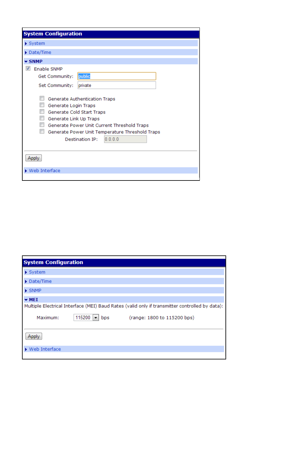
Configure SNMPsettings
1. On the main menu, click System > SNMP. The SNMP Settings page displays.
2. Select Enable SNMP.
3. Enter the community (public or private).
4. Select the type or types of traps you wish to enable.
5. Click Apply.
Configure network and serial ports Autoconnection
Digi One Family and PortServer TS Family
54
Configure MEI settings
MEI settings apply to EIA-422/485 Half-Duplex (2 wire) ports only. See Configure MEIsettings for
details on MEI.
1. Select System > MEI.
2. Select the baud rate from the Maximum drop-down box.
3. Click Apply for configuration to take effect.
Autoconnection
The autoconnection feature allows you to configure a user to access the device server and then be
automatically connected to a host on the LAN.
You can implement autoconnection in the following ways:

Configure network and serial ports Autoconnection
Digi One Family and PortServer TS Family
55
n By port, where all port users are automatically connected to the same host. The device server
is completely transparent to them.
n By user, where a user is required to log on and may be required to supply a password. Once the
user is authenticated, an automatic connection to a host is made.
Configure a port for autoconnection
1. Click Configuration > Serial Ports.
2. Click the TCP Sockets Port Profile. Note that TCP Sockets is the port profile to use for
Autoconnection.
3. Click Apply.
4. Select Automatically establish TCP connections and the appropriate parameters. Use the
Help button for additional information.
5. Click Apply.
6. Click Reboot for changes to take effect.
7. To return to the main Ports menu, choose Menu > Ports.
Configure a user for autoconnection
1. Click Users from the menu.
2. Choose New User.
3. Enter a username and click Next.
4. Select the Terminal/Terminal Emulation user profile and click Next.
5. Select Automatically connect to a ...
6. Be sure to specify the following:
n Hostname or IP address that will be the destination
n Service (Telnet, Rlogin, raw TCP, or SSL)
n Destination TCP port number, which determines the type of connection for this user
(such as 23 for Telnet)
7. Click Next and choose to verify the settings.
8. Click Finish to save settings.

Configure Industrial Automation (IA)
The Digi Industrial Automation (IA) capabilities enable Digi products to identify and intelligently
manage communications using several common Industrial Automation protocols. This chapter
discusses using Digi products with Industrial Automation (IA) applications, including configurations
that work for your for IA applications, and the configuration tasks required to use your Digi product in
an IA environment. The content in this chapter assumes you are familiar with the basics of the
industrial protocols you need to implement.
Key terms
Industrial Automation involves several key terms:
Term Description
Com Port Redirection
A method of redirecting the serial data
generated by a PC-based master to a slave
connected to a port on a network-based
device server. In this scheme, the master
“thinks” that it is communicating with a
device connected to a serial port on the PC
system when, in fact, the data is
encapsulated in network packets and
transported across the network to a device
connected to a serial port on the Digi device
server. Many applications, written to support
serial communication only, require this
service in order to communicate over the
Ethernet.
IA
Abbreviation for industrial automation.
master (or protocol master)
The host or IA device that initiates all
communication with a protocol slave.
multi-master
Any configuration in which more than one
master simultaneously communicates with a
slave.
Digi One Family and PortServer TS Family
56

Configure Industrial Automation (IA) Industrial Automation configuration wizard
Digi One Family and PortServer TS Family
57
Term Description
protocol request A message generated by the master and sent
to the slave that requests information or
issues a command.
protocol response
A message generated by the slave in
response to a protocol request from the
master.
slave (or protocol slave)
The device that responds to requests from
the master.
TCP socket (or TCP socket service)
A type of network service that uses TCP to
ensure reliability. When this manual discusses
TCP sockets, it means that IA protocol
messages are encapsulated in network
packets and transported across the network
using a standard network service. Many
applications support connections to devices
using TCP socket.
TCP tunnel
A TCP socket connection in which a master is
connected to the serial port of one device
server and a slave to the serial port of
another Digi device.
UDP sockets (or UDP socket service)
Similar to TCP socket service (discussed
above) except that the UDP protocol is used
instead of TCP, which means that the
reliability service TCP performs is not
provided. Advantages of UDP socket service
are slightly less protocol overhead and
support for multicasting. Some applications
support connections to devices using TCP
socket.
UDP tunnel
A UDP socket configuration in which a master
is connected to the serial port of one device
server and a slave to the serial port of
another Digi device.
Industrial Automation configuration wizard
To help you configure your Digi product for use in an IA application, a configuration wizard and several
configuration profiles, or scenarios, are provided.
To launch the wizard:
1. Log in to web interface.
2. Click Applications > Industrial Automation.
3. Click the link in the text: For a guided installation, launch the Industrial Automation
Wizard.

Configure Industrial Automation (IA) Industrial Automation configuration profiles
Digi One Family and PortServer TS Family
58
Industrial Automation configuration profiles
This chapter discusses several common configuration profiles for industrial automation:
n Serial Bridge profile: master and slave connected to Digi ports
n Modbus profile: serial-connected slave
n Modbus profile: serial-connected master
n Omron family profile: serial-connected slave
n Omrom family profile: serial-connected master
n Other serial port protocol profile: serial-connected slave
n Other serial port protocol profile: serial-connected master
Industrial Automation configuration procedures
This chapter presents procedures for configuring these common industrial automation configuration
profiles:
n Configure a serial-connected slave:generic procedure
n Configure a serial-connected master: generic procedure
n Configure a serial-connected master: TCP/UDP sockets
n Configure a serial-connected slave: other IA protocol
n Configure a serial-connected master: other IAprotocol
n Set up COM port redirection

Configure Industrial Automation (IA) Serial Bridge profile: master and slave connected to Digi ports
Digi One Family and PortServer TS Family
59
Serial Bridge profile: master and slave connected to Digi ports
Use this profile to connect a protocol master to the serial port of one device server and the protocol
slave (or slaves) to the serial port of another device server. This profile, which is often called a serial
bridge, is applicable to environments that use most IA serial port protocols and to multi-master
environments as well. The network is completely transparent to the serial devices, which means they
do not have to be reconfigured.
Configuration Options
The serial port connections must be configured to meet the requirements of the attached device,
which can be Modbus ASCII, Modbus RTU, DF1 Full-Duplex, Omron Hostlink, Omron FINS, and Omron
CompoWay/F. It can also be a serial port protocol that meets Digi’s definition of a “user defined”
protocol, that is, one that has fixed header and trailer strings that bound all message packets and
where each protocol request is followed by a single response.
For the network connection, Digi recommends TCP sockets, which works regardless of the serial port
protocol specified and provides an efficient and reliable network service. Another option is UDP
sockets, which also works with all the serial port protocols, although it lacks TCP socket reliability. For
Modbus devices, Modbus/TCP is an option, and for DF1 Full-Duplex devices, Allen Bradley Ethernet and
Ethernet/IP are options.
Setup Information: Slave Side
See Configure a serial-connected slave:generic procedure.
Setup Information: Master Side
To configure TCP socket or UDP socket communication, see Configure a serial-connected master:
TCP/UDP sockets.
To configure any of the other network communication protocols, see Configure a serial-connected
master: generic procedure.

Configure Industrial Automation (IA) Modbus profile: serial-connected slave
Digi One Family and PortServer TS Family
60
Modbus profile: serial-connected slave
Use this profile to connect a slave device (or devices) using Modbus RTU or Modbus ASCII. This profile
is applicable to environments in which multiple masters will control the slave or slaves.
Configuration Options
The serial port connection must be configured for the protocol required by the slave, in this case
Modbus RTU or Modbus ASCII.
The network connection usually does not require configuration. The only exception is if the master
requires COM port redirection. In this case, the master is an application that resides on a PC, such as
a Microsoft Windows system, and communicates only with devices on COM ports.
Setup Information
To configure the serial port for Modbus ASCII or Modbus RTU, see Configure a serial-connected
slave:generic procedure.
To setup a PC and the device server for COM port redirection using RealPort, see Set up COM port
redirection.

Configure Industrial Automation (IA) Modbus profile: serial-connected master
Digi One Family and PortServer TS Family
61
Modbus profile: serial-connected master
Use this profile to connect a master device using Modbus RTU or Modbus ASCII to the serial port of
the device server.
Configuration Options
The serial port connection must be configured for the protocol required by the master, in this case
Modbus RTU or Modbus ASCII. If the remote slave supports TCP socket communication, which is the
case if the remote slave is connected to another device server, Digi recommends this option.
Modbus/TCP is the other supported network option. This master can be configured to control up to 8
slaves.
Setup Information
To configure the port for Modbus ASCII or Modbus RTU and the network for TCP socket
communication, see Configure a serial-connected master: TCP/UDP sockets.
To configure the port for Modbus ASCII or Modbus RTU and the network for Modbus/TCP, see
Configure a serial-connected master: generic procedure.

Configure Industrial Automation (IA) DF1 profile: serial-connected slave
Digi One Family and PortServer TS Family
62
DF1 profile: serial-connected slave
Use this profile to connect a slave device (or devices if multiple slaves are connected) using the DF1
Full-Duplex protocol.
Configuration Options
The serial port connection must be configured for the protocol required by the slave, in this case DF1
Full-Duplex.
The network connection usually does not require configuration. The only exception is if the master
requires COM port redirection. In this case, the master is an application that resides on a PC, such as
a Microsoft Windows system, and communicates only with devices on COM ports.
Setup Information
To configure the serial port of the device server for DF1 Full-Duplex, see Configure a serial-connected
slave:generic procedure.
To set up a PC and the device server for COM port redirection using RealPort, see Set up COM port
redirection.

Configure Industrial Automation (IA) DF1 profile: serial connected master
Digi One Family and PortServer TS Family
63
DF1 profile: serial connected master
Use this profile to connect a master device using the DF1 Full-Duplex and protocol to the serial port.
Configuration Options
The serial port connection must be configured for the protocol required by the master, in this case
DF1 Full-Duplex. If the remote slave supports TCP socket communication, which is the case if the
remote slave is connected to another device server, Digi recommends this option. For DF1 Full-Duplex
users, Allen Bradley Ethernet and Ethernet/IP are other supported network options.
Setup Information
To configure the port for DF1 Full-Duplex and the network for TCP socket communication, see
Configure a serial-connected master: TCP/UDP sockets.
To configure the port for DF1 Full-Duplex and the network for Allen Bradley Ethernet or Ethernet IP,
see Configure a serial-connected master: generic procedure.

Configure Industrial Automation (IA) Omron family profile: serial-connected slave
Digi One Family and PortServer TS Family
64
Omron family profile: serial-connected slave
Use this profile to connect a slave device (or devices) using one of the Omron serial port protocols,
Hostlink, FINS, or CompoWay/F.
Configuration Options
The serial port connection must be configured for the protocol required by the slave, Hostlink, FINS, or
CompoWay/F.
The network connection usually does not require configuration. The only exception is if the master
requires COM port redirection. In this case, the master is an application that resides on a PC, such as
a Microsoft Windows system, and communicates only with devices on COM ports.
Setup Information
To configure the serial port of the device server for any of the Omron protocols, see Configure a serial-
connected slave:generic procedure.
To setup a PC and the device server for COM port redirection using RealPort, see Set up COM port
redirection.

Configure Industrial Automation (IA) Omrom family profile: serial-connected master
Digi One Family and PortServer TS Family
65
Omrom family profile: serial-connected master
Use this profile if you want to connect a master device to the serial port using one of the Omron serial
port protocols, Hostlink, FINS, or CompoWay/F.
Configuration Options
The serial port connection must be configured for the protocol required by the master, in this case
Hostlink, FINS, or CompoWay/F. If the remote slave supports TCP socket communication, which
includes a slave connected to another device server, Digi recommends this network option. UDP
Sockets is another supported network option.
Setup Information
To configure the port for one of the Omron protocols and the network for TCP or UDP socket
communication, see Configure a serial-connected master: TCP/UDP sockets.

Configure Industrial Automation (IA) Other serial port protocol profile: serial-connected slave
Digi One Family and PortServer TS Family
66
Other serial port protocol profile: serial-connected slave
Use this profile if you want to connect a slave device to the serial port using any IA serial port protocol
not previously discussed.
Configuration Options
In this configuration, you do not set up the port of the device server for an IA protocol. If you plan to
use RealPort for COM port redirection, you simply set up the port for RealPort. If you plan to have the
master access the device server using TCP or UDP sockets, you simply configure the standard serial
port parameters required by the attached slave, such as line speed, number of data bits, and parity
scheme. No special network configuration is required in either case.
Setup Information
To set up the device server for RealPort, see Set up COM port redirection.
To set up the port for an “unsupported” IA protocol, see Configure a serial-connected slave: other IA
protocol.

Configure Industrial Automation (IA) Other serial port protocol profile: serial-connected master
Digi One Family and PortServer TS Family
67
Other serial port protocol profile: serial-connected master
Use this profile if you want to connect a master device to the serial port using any IA serial port
protocol not previously discussed.
Configuration Options
In this configuration, you do not set up the port of the device server for an IA protocol. You simply
configure the standard serial port parameters required by the attached master, such as line speed,
number of data bits, and parity scheme and then configure the port for autoconnection.
Setup Information
See Configure a serial-connected master: other IAprotocol.

Configure Industrial Automation (IA) Configure a serial-connected slave:generic procedure
Digi One Family and PortServer TS Family
68
Configure a serial-connected slave:generic procedure
Use this procedure when a protocol slave is connected to the serial port of the device server. Use it
except when the associated master requires COM port redirection. (See "Set Up COM Port
Redirection" on page 76 for information.)
1. Access the web interface by entering the device server IP address in a browser’s URL window.
2. Log in to the web interface.
3. Click Setup Wizards > Industrial Protocols.
4. Choose the serial port protocol required by the slave that is connected to the serial port.
5. Choose Slave as the device type.
Any number of network masters can communicate with the slave.

Configure Industrial Automation (IA) Configure a serial-connected master: generic procedure
Digi One Family and PortServer TS Family
69
Configure a serial-connected master: generic procedure
Use this procedure when a protocol master is connected to the serial port of the device server. Use it
except when the master requires TCP socket or UDP socket communication. See Configure a serial-
connected master: TCP/UDP sockets.
Procedure
1. Access the web interface by entering the device server IP address in a browser’s URL window.
2. Log in to the web interface.
3. From the main menu, choose Setup Wizards > Industrial Protocols.
4. Choose the serial port protocol required by the master.
5. Choose Master as the Mode.
6. Configure up to 8 network slaves.

Configure Industrial Automation (IA) Configure a serial-connected master: TCP/UDP sockets
Digi One Family and PortServer TS Family
70
Configure a serial-connected master: TCP/UDP sockets
Use this procedure in the following situations:
n When a protocol master using one of the supported serial port protocols (Modbus ASCII,
Modbus RTU, DF1 Full-Duplex, FINS, Hostlink, CompoWay/F or a protocol that meets Digi’s
definition of a “user-defined” protocol) is connected to the serial port.
n When the master requires TCP or UDP sockets for network communication.
Procedure
1. Access the web interface by entering the device server IP address in a browser’s URL window.
2. Log in to the web interface.
3. From the main menu, choose Setup Wizards > Industrial Protocols.
4. Choose the serial port protocol required by the master.
5. Choose Master as the Mode.
6. Configure up to 8 network slaves.
7. Change the default socket number only if required.

Configure Industrial Automation (IA) Configure a serial-connected slave: other IA protocol
Digi One Family and PortServer TS Family
71
Configure a serial-connected slave: other IA protocol
Use this procedure in the following situations:
n When the device connected to the serial port is a slave that is using a “non-supported” serial-
port protocol, that is, the serial port protocol is not Modbus ASCII, Modbus RTU, DF1 Full-
Duplex, FINS, Hostlink, CompoWay/F, or a protocol that meets the definition of a “user-
defined” protocol.
n When you do not want to set up the device server for RealPort COM Port redirection.
n When multiple masters will not be communicating with this slave.
Procedure
1. Access the web interface by entering the device server IP address in a browser’s URL window.
2. Log in to the web interface.
3. From the main menu, choose Configure > Port.
4. From the Port configuration page, set the Device type to Printer, adjust other serial port
communication parameters as required by the connected slave, and click Submit.
5. Choose Advanced, check Binary Mode, and click Submit.

Configure Industrial Automation (IA) Configure a serial-connected master: other IAprotocol
Digi One Family and PortServer TS Family
72
Configure a serial-connected master: other IAprotocol
Use this procedure when the device connected to the serial port is a master that is using a “non-
supported” serial-port protocol, that is, the serial port protocol is not Modbus ASCII, Modbus RTU, DF1
Full-Duplex, FINS, Hostlink, CompoWay/F, or a protocol that meets the definition of a “user-defined”
protocol.
Procedure
1. Access the web interface by entering the device server IP address in a browser’s URL window.
2. Log in to the web interface.
3. From the main menu, choose Configure > Port.
4. From the Port configuration page, set the Device type to Modem In, adjust other serial port
communication parameters as required by the connected master, then choose Submit.
The Terminal type field does not matter.
5. If you want to configure the port to launch an automatic connection to the slave, click
Advanced.
6. Choose Enable Autoconnect.
7. Specify the IP address of the slave.
8. Specify a TCP port to use for this connection. If this is a connection to another device server,
use 2101 as the TCP port number.
9. If you want the autoconnection to launch immediately, choose Force DCD.
10. Choose Binary Mode.
11. If you want to enable UDP sockets (instead of TCP sockets), choose UDP Serial, use the online
help for information on completing configuration task.
12. When you complete configuration, click Submit.

Configure Industrial Automation (IA) Set up COM port redirection
Digi One Family and PortServer TS Family
73
Set up COM port redirection
Use these procedures when a slave is connected to the serial port of the device server and the
master, which must be an application residing on a Microsoft Windows system, requires COM port
redirection.
Setup Tasks: Overview
To enable Com port redirection--which requires that RealPort software be running on the same PC as
the master application--complete the following tasks:
1. Configure the serial port for RealPort. See Configure the Serial Port for RealPort below.
2. Install RealPort software on a host system.
3. Configure the port on the RealPort PC. See the PC’s documentation for information on
configuring serial ports.
Configure the Serial Port for RealPort
Use this topic for information on configuring the Digi device.
1. Access the Digi device web interface from a web browser by entering the device’s IP address in
the browser’s URL window.
2. Log into the web interface.
3. Do one of the following:
n If the slave is using a supported serial port protocol:
a. Choose Port from the main menu.
b. Set the Device Profile to IA.
c. Click Apply and enter the protocol information.

Configure Industrial Automation (IA) Set up COM port redirection
Digi One Family and PortServer TS Family
74
n If the slave is not using a supported serial port protocol:
a. Install the RealPort driver on your SCADA system. Refer to the RealPort Installation
Guide as needed.
4. Use the RealPort port profile and the associated help text to configure the RealPort driver with
the IP address and TCP port number used by the device server.
5. Follow the prompts to complete configuration of the RealPort driver.

Configure Industrial Automation (IA) RealPort:Determine whether to install RealPort
Digi One Family and PortServer TS Family
75
RealPort:Determine whether to install RealPort
Trying to decide if you need to install RealPort? Use these decision maps to help you decide. Follow
the scenario closest to what you are trying to do, then follow the questions for additional directions.

Configure MEIsettings
This section describes configuring MEI (Multiple Electrical Interface) settings through the web
interface for the PortServer TS 8 MEI* and PortServer TS 16 MEI*. The internal MEI settings are
switched to EIA-232 by default.
*Except for the PortServer TS 8 MEI and PortServer TS 16 MEI devices, the remaining Digi TS Family
have external DIP switches for MEI settings.
About MEIsettings
PortServer TS 8/16 MEI devices are shipped with the ports switched to EIA-232 by default. The 232
drivers will generate voltages of 6V max. This voltage is well within the tolerances of EIA 422/485. The
232 drivers are current limited so they can’t over-drive another EIA-422/485 output and damage their
devices.
The same engineering applies if a port is set at EIA-422 and a 232 device is connected to it. The
voltage generated is within the tolerance of the serial device and will not damage either device.
In either case, your serial device may or may not produce ‘data chatter’ - that is, text strings that have
no meaning. This is an indication that the MEI settings are not in agreement and should be configured.
If there is a loss of power to the unit, the device will not lose the MEI configuration. After it boots up, it
will recall and apply the last MEI settings.
Configure MEI switches
1. Log into the Digi PortServer TS.
2. Click Serial Ports > port #.
3. Select your port profile for your environment and click Apply.
4. Click MEI Serial Settings.
5. Select the Tx Control setting for your scenario.
n Select Tx Control > Always on if this device is the only one transmitting on one wire
pair, such as a single master in a master/slave configuration or if only two devices are
attached.
n Select Tx Control > Auto if multiple devices need to share the bus in a dual master
scenario or if the device is acting as slave in a multidrop environment. See Four-wire
multi-drop scenarios for more information about multi-drop scenarios.
6. Click Apply and the settings will take effect.
7. Repeat steps 2-6 for each port.
8. If you have not done so already, connect your serial device to the appropriate serial port.
Digi One Family and PortServer TS Family
76

Configure MEIsettings Four-wire multi-drop scenarios
Digi One Family and PortServer TS Family
77
Set the supported baud rate for multi-drop support
The PortServer TS 8/16 MEI requires setting a baud rate range in order to perform the automatic
transmitter control. This setting does not influence the performance in EIA-232 mode or for EIA-
422/485 configurations where the transmitter is always on.
The range supported by default is: 50 -230400 bps
To change the supported baud rate range
1. Select System > MEI.
2. From the Baud Rate drop-down box, select the appropriate baud rate.
3. Select Enable all serial ports (to enable the serial port transmitter) if appropriate.
4. Click Apply for configuration to take effect.
Four-wire multi-drop scenarios
There are two scenarios of devices on a four-wire multi-drop network: the Master and the Slave. A
Master has a dedicated pair of wires to talk to the Slaves. The Slaves share a return pair to the Master
and need to control their transmitters so that only one device at a time uses that pair. Following are
the specific procedures to set up a Master or Slave MEI setting.
MEIconfiguration for a single master
1. Click Serial Ports > port # > MEI Serial Settings.
2. Select 422/485, Tx Control > Always on.
3. Select Enable alternative pinout (altpin). This option is only enabled with 4 Wire. See Pinouts
for more information.
4. Click Apply for settings to take effect.
MEIconfiguration for a slave
1. Click Serial Ports > port # > MEI Serial Settings.
2. Select 422/485, Tx Control > Auto.
3. Select Enable alternative pinout (altpin). This option is only enabled with 4 wire. See Pinouts
for more information.
4. Click Apply for settings to take effect.
Note You do not need to reboot after you click Apply for MEI settings to take effect.
Pinouts
Pin
number
EAI-232
signal
Standard 10-Pin EIA-
422/485 Signal (4/8 Wire)
Optional 8 pin EIA-
422/485 Signal (Alt-4-
Wire)
EIA-485 Signal
(2-Wire Mode)
01 RI TXD- (B)

Configure MEIsettings Four-wire multi-drop scenarios
Digi One Family and PortServer TS Family
78
Pin
number
EAI-232
signal
Standard 10-Pin EIA-
422/485 Signal (4/8 Wire)
Optional 8 pin EIA-
422/485 Signal (Alt-4-
Wire)
EIA-485 Signal
(2-Wire Mode)
02 DSR RxD- (B) RxD- (B) Data- (B)
03 RTS RTS+ (A) TxD+ (A)
04 CGND CGND CGND CGND
05 TxD TxD+ (A)
06 RxD RxD+ (A) RxD+ (A) Data+ (A)
07 SGND SGND SGND SGND
08 CTS CTS+
09 DTR RTS- (B) TxD- (B)
10 DCD CTS- (B)

Configure embedded modem
The PortServer TS 1 M MEI and PortServer TS 3 M MEI function as both terminal server and modem.
The embedded modem can be used with PPP, dial-in, dial-out, or auto answer and conforms to the
standard AT command interface.
The PortServer TS 1 M MEI and PortServer TS 3 M MEI allow:
n Remote monitoring
n Diagnostics
n Data collection
n Dial-up or Ethernet connectivity
For a complete AT command reference, see the AT Command Reference (Digi part number 90000270)
on the Digi website.
The remaining ports can be configured the same as any Digi TS Family product, either through the
web interface or command line.
Connect hardware
The PortServer TS 1/3 M MEI comes with a bidirectional cable for connecting the modem (port 1) to
the phone line.
1. Plug the cable with the ferrite end into the modem port.
Digi One Family and PortServer TS Family
79

Configure embedded modem Configure device settings
Digi One Family and PortServer TS Family
80
2. Plug other end into phone line.
3. Connect Ethernet.
4. Connect power supply.
Configure device settings
1. Assign an IP address to the Digi device. See Configure the IPaddress.
2. Open a web browser and enter the device’s IP address in the URL bar.
3. Log in to the web interface.
4. Select Serial Ports > Change profile.
5. Select the appropriate port profile (Custom shows all options).

Configure embedded modem Configure device settings
Digi One Family and PortServer TS Family
81
6. Enter the appropriate parameters and click Apply to save.
7. Click Reboot for changes to apply.

Configure power over serial ports
The Serial Power feature available for the PortServer TS P MEI Series allows the Digi device to power
a serial device (power out) or use a serial device to power the Digi device (power in). The advantage of
this feature is to eliminate an external power supply.
Power out is available on all ports through Ring Indicator (RI) or Data Terminal Ready (DTR). Power in
is available only through RI and only on port one (1). The Serial Power feature is active on a specific
port when that port is configured for RS 232 operation.
n The power out budget equals one (1) watt (the total amount of power available). The available
power can be divided in any combination between the ports but the following rules must be
observed:
l RI = 5 volts @ up to 200 mA (max)
l DTR = 9 volts @ up to 100 mA (max)
l You may use DTR or RI as the source of power (power out) on any port but you may not use
both DTR and RI on the same port.
n Pinout information:
l RI is pin 1
l DTR is pin 9
n RI signaling is lost when the pin is used for power.
Configure Ring Indicator (RI) power
RIpower in
Ring Indicator (RI) power in accepts power into the Digi device only on port one. Power in is available
using the RI pin. The Digi device requires power in the range of 9-30 VDC @ 525mA (max). Ports 2, 3,
and 4 can still supply power to a serial device through the RI or DTR pins for each port. When using
power in through the RI, the external power supplies (both powered Ethernet and the barrel
connector power supply) are inoperative. Altpin will not work for RI power in.
1. Open the device case and move the black jumper to the following settings:
P-6 jumper on pins 1 and 2
Note When the jumper is placed correctly for power in, the jumper will set on the pins closest
to the edge of the board. The left arrow indicates the open pin and the right arrow is pointing
to the jumper.
Digi One Family and PortServer TS Family
82

Configure power over serial ports Configure DTRpower: power out
Digi One Family and PortServer TS Family
83
2. Close the device unit enclosure.
RIpower out
RI power out is available on all ports. The total power budget for this feature is one (1) watt not to
exceed 5 volts @ up to 200mA on any single port. The following procedure assumes the unit will only
be used for RI power out.
1. Set the port DIP switches to the following places: switch 1 and 3 are up and 2 and 4 are down.
See Serial power table.
2. Enable the RI power through the web interface.
3. Connect power supply with the barrel-connector power supply provided with the device or use
powered Ethernet.
Note If the unit will be used with RI power in (port 1 only), set the jumper to the following
setting: P-6 jumper on pins 1and 2 and do not use an external power source. Port 1 cannot be
used for both power in and power out.
Configure DTRpower: power out
Data Terminal Ready (DTR) power out is the factory default on the Digi device. Total power budget for
this feature is one (1) watt not to exceed 9 volts @ up to 100mA to any single port.
1. Set the port DIP switches to EIA 232 (switch 1 is up, 2, 3, and 4 are down) to enable DTR power.
2. Open the port and set DTR high.
Note The graphic below shows the pins to verify the jumper position. The default position has the
jumper on the two pins furthest from the edge. DO NOT MOVE THE JUMPER FROM THE DEFAULT
UNLESS USING RI POWER IN.

Configure power over serial ports Serial power table
Digi One Family and PortServer TS Family
84
If you are having trouble with your unit after using the Power over port feature, you may have tripped
the circuit breaker in the unit. You can identify this by the RI or DTR signal indicators found in the
System Information under Administration on the main menu in the web interface. Click the port
number using serial power. (Remember serial power out is unavailable if the MEI settings are not
232.)
Under serial power will be a message if the breaker is tripped. Follow the instructions to reset.
From the command line, issue the two commands below for additional information.
n display circuitbreaker: Display the status of the circuit breaker
n set config circuitbreaker=reset: Reset the circuit breaker.
n set config: Display the status of the circuitbreaker state.
Serial power table
Use this table for summary information for a serial power setup.
DTRpower RIpower
Out Out In
Switch settings
DTRsetting DTRON DTROFF DTROFF
Ports allowed 1, 2, 3, 4
1*, 2, 3, 4
*unless port 1 is
used for power
IN
1

Configure power over serial ports Serial power table
Digi One Family and PortServer TS Family
85
DTRpower RIpower
Out Out In
Jumper pin settings
P-6 jumper on pins 2
& 3
(factory default)
P-6 jumper on
pins 2 & 3
(factory default)
P-6 jumper on
pins 1 & 2
Power budget
9 v @ up to 100 mA
one watt
5 v @ up to 200
mA
one watt
9 -30 V @ up to
525 mA (max)

Digi Remote Power Management
Digi Remote Power Manager (Digi RPM) is an intelligent power distribution unit for remote power
management that can be used with PortServer TS Family products. When integrated with PortServer
TS products, Digi RPM allows power management and device configuration from anywhere across the
corporate LAN/WAN. It provides an easy solution for the supervisory control and management of
attached electrical devices.
A Digi RPM integrated with your PortServer TS product can be used to:
n Remotely power on/off/reboot devices. Power control consists of three basic functions: on, off,
and reboot (power cycle).
n Measure electrical load and monitor ambient temperature.
n Configure alarms for 24/7 “real-time” monitoring and notification of out-of-spec conditions,
including load and ambient temperature. A user interface is provided for configuring these
alarms. Digi RPM also provides statistics on average/apparent power, RMS voltage/current,
circuit breaker status and maximum current.
n Integrate with select PortServer TS terminal servers and device servers for console and power
management over Ethernet.
Digi RPM is available in both eight-port 1U rack-mountable and ten-port 0U rack-mountable versions.
Configuration scenarios using Digi RPM
There are two typical scenarios when using Digi RPM and the power management feature with
PortServer TS Family products:
Digi One Family and PortServer TS Family
86

Digi Remote Power Management Configuration scenarios using Digi RPM
Digi One Family and PortServer TS Family
87
n A non-serial device connected to Digi RPM
n A serial device managed by a PortServer TS device, but powered by Digi RPM
Non-serial device connected to Digi RPM
The simplest scenario is a non-serial device connected to the Digi RPM; for example, an environmental
sensor controller or a tape backup device. The Digi RPM’s power-management settings are configured
and accessed through the web interface for the PortServer TS device to which it is connected. This
illustration shows a Digi RPM configured through a PortServer TS 16 for use in powering non-serial
devices.
Serial device managed by PortServer TS but powered by Digi RPM
The second configuration scenario involves a serial device, such as a router or server, that is managed
through a port on a Digi PortServer TS device, but has its power supply mapped through the Power
Management feature. The Digi RPM and power-management settings are configured and accessed
through the web interface for the PortServer TS device.
After configuration of the devices in this scenario is complete, you need only reference the console
management port on device server to also manage power. The Power Management feature handles
the relationship of a specific outlet to a serial device as if the power supply were also connected to the
same port as the serial device. In other words, you do not need to see the physical connection or
remember which outlet controls a specific serial device after configuration - the PortServer TS device
server does that for you. The following illustration shows a Sun server configured through a serial port
connection on the PortServer TS 16.
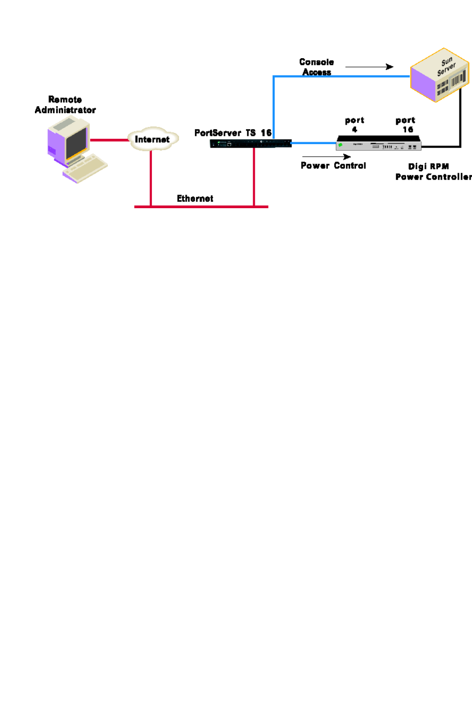
Digi Remote Power Management Digi RPM configurable from web interface or command line
Digi One Family and PortServer TS Family
88
Digi RPM configurable from web interface or command line
Power management through the Digi RPM can be configured from either the web interface or
command-line interface for your PortServer TS device that is connected to the Digi RPM.
Web interface
From the web interface, which this guide emphasizes, power management is configured through the
serial port settings:
Configuration > Serial Ports > port > Port Profile > Power Management
Once set up, power management equipment is monitored and controlled at:
Management > Power
Command line
From the command line, the set powerunit command configures power management options, and
the power command controls and displays the status of the Digi RPM. See the Digi One and
PortServer TS Family Command Reference for these command descriptions.
Process for configuring and managing Digi RPM
From the web interface, configuring and managing the Digi RPM involves these steps:
1. Connect the Digi RPM to the PortServer TS device and power up.
2. Configure Digi RPM settings, including optional thresholds and alarms.
3. Configure outlets on the Digi RPM, including user access permissions to the outlets.
4. Manage power devices and power controllers.
n Manage power devices: view status of outlets and change status as needed (on, off,
reboot).
n Manage power controllers: manage individual outlets or all outlets, view current
settings in the Digi RPM, including current voltage and temperature status.

Digi Remote Power Management Connect Digi RPM to PortServer TSdevice and power up
Digi One Family and PortServer TS Family
89
Connect Digi RPM to PortServer TSdevice and power up
To connect the Digi RPM to your PortServer TS device, use the PortServer TS to SunNetra (P/N
63000222-02) cable provided with the Digi RPM unit. Plug one side into the “Console” port of the Digi
RPM unit and the other into any port of the PortServer TS product.
Make sure that the DIP switches of the unit are set to “Off.” Plug the Digi RPM into an appropriate
power source and turn it on.
Configure Digi RPM settings
A Power Management port profile is available for use to configure your Digi PortServer device and its
serial ports for use with the Digi RPM. This port profile is used to control and manage the Digi RPM in
its power-control actions (on, off, reboot).
1. Log in to web interface.
2. Select Configuration > Serial ports.
3. Select the port number of the serial port you want to connect to the Digi RPM.
4. The Power Management port profile has configuration settings appropriate for a serial port
connected to a Digi RPM power controller. If the Power Management port profile has not
already been associated with the port through the Digi Device Setup Wizard, click Change
Profile. Select Power Management from the list of port profiles and click Apply.
5. In the Profile Settings part of the page, select whether the power controller settings will be
automatically detected or whether you will configure the settings yourself.
n Automatically Detect Power Controller: Configuration settings for the Digi RPM are
automatically detected after clicking Apply. Once the Digi RPM is detected, the settings
are populated on the page. The Manually Configure Power Controller option is
selected, allowing you to edit the settings as needed. You can correct the number of

Digi Remote Power Management Configure outlets
Digi One Family and PortServer TS Family
90
ports, if necessary, or edit the port title.
n Manually Configure Power Controller: Configuration settings for the Digi RPM power
controller are manually entered. Enter the following, then click Apply:
Manufacturer: Select the manufacturer of the power controller.
Outlets: Enter the number of outlets on the Digi RPM power controller.
6. Optionally, set thresholds and alarms for the Digi RPM and click Apply.
Digi RPM can be configured to generate an audible alarm and an SNMP trap when either of the
following types of thresholds are reached on the unit:
n Current Alarms (amps): The current alarm threshold monitors the electric current on
the Digi RPM. You can set up to four thresholds, depending on the number of current
sensors on the Digi RPM. When the sensor's specified amperage level is reached, the
Digi RPM will emit an audible alarm. Current alarm thresholds are configurable in the
range of 0.1 to 99.9 Amps.
To generate current alarm threshold SNMP traps, you must also go to the System >
SNMP configuration page and select Generate Power Unit Current Threshold Traps
option, and specify a destination IP address for the SNMP trap.
n Temperature (°C): This alarm threshold monitors the temperature on the Digi RPM. You
can set up to four thresholds, depending on the number of temperature sensors on the
Digi RPM. When the sensor's specified temperature is exceeded, the Digi RPM will emit
an audible alarm.
Temperature alarm thresholds are configurable in the range of 0.1 to 99.9 °C
To generate temperature threshold traps, you must also go to the System > SNMP
configuration page, select Generate Power Unit Temperature Threshold Traps
option, and specify a destination IP address for the SNMP trap.
Configure outlets
Next, configure the PortServer TS to link serial ports to outlets on the Digi RPM. From each outlet on
the Digi RPM, you can set a name for it, tie its use to a serial port, and control user access to the
outlet for power management.
1. On the Port Profile page, click Controller Outlets. A list of other Digi RPM power controller’s
outlets is displayed, along with a summary of each outlet’s current configuration. The number
of outlets displayed is the same as the value entered for Outlets on the Controller Settings
page.

Digi Remote Power Management Configure outlets
Digi One Family and PortServer TS Family
91
2. You can either edit outlet settings or clear them.
n To edit the settings of a power outlet, click on that outlet's link under the Outlet or
Device Name heading.
n To clear the settings of a power outlet, click on Unplug Device... under the Action
heading, and confirm that you want to clear the settings.
3. The Power Outlet Configuration page is displayed.
n In the Device Name field, enter a name for the device plugged into this power outlet. If
you give the same device name to multiple devices, such as “router,” they can be
managed as a single entity. For example, multiple servers that have been assigned the
same Device Name can be shut down or rebooted.
n If the powered device is a serial device, in the Serial Port field, specify the serial port to
which the powered device is connected.

Digi Remote Power Management Manage power devices and power controllers
Digi One Family and PortServer TS Family
92
n In the Power Management Access section, configure user access permissions to the
outlet.
Users can be assigned permission to manage the outlet. A user with access permissions
to the outlet will have the option to power a connected device on or off or reboot the
device.
Individual users must already be configured before they can be assigned to manage
power outlets. To add users, go to Configuration > Users.
Users that currently have permission to control the outlet are listed in the
Username/Action table.
To allow a user access permissions to the outlet: In the bottom row, select a Username
and click Add.
To restrict a user from accessing the outlet: Click Remove.
Apply these users to all outlets with the same device name:
Apply these users to all outlets with the same serial port:
These options allow you to easily assign the same users to manage each outlet with the
same device name or serial port.
4. Click Apply and repeat steps 2-3 for each outlet you want to configure.
Manage power devices and power controllers
After power devices and controllers are configured, you can manage them. From the web interface, go
to Management > Power. From the command-line interface, issue the “power” command.
In the web interface, there are two power-management actions: Manage Power Devices and Manage
Power Controllers.
Manage power devices
The Manage Power Devices page shows the status of outlets and allows you to change the power-
cycle action of each outlet (on, off, reboot).

Digi Remote Power Management Manage power devices and power controllers
Digi One Family and PortServer TS Family
93
To change the power-cycle action, click Power and choose the available action. This change affects
the power-cycle action for all outlets assigned the same device name.
Manage power controllers
The Manage Power Controllers page allows you to get a quick update of the status of Digi RPM power
controllers configured for use with your PortServer TS device, and to power all outlets for each Digi
RPM power controller.

Digi Remote Power Management Manage power devices and power controllers
Digi One Family and PortServer TS Family
94
Display power controller status
In the list of power controllers, the Status field shows the brief status of the Digi RPM power
controller, such as whether it is connected or disconnected.
For more detailed status of the power controller, click the power controller’s name, for example, Digi
RPM on Port 2. The Controller Status page displays the current state of the Digi RPM power
controller, including circuit breaker condition, temperature threshold, current temperature, RMS
voltage, alarm threshold, RMS current, and the maximum current detected.
Clicking the Reset button resets the Max Current Detected value to 0.0 amps.
The Refresh button refreshes the status values.
Manage all outlets at once
From the Manage Power Controllers page, you can power all outlets for the Digi RPM by clicking
Power all Outlets.

Digi Remote Power Management Manage power devices and power controllers
Digi One Family and PortServer TS Family
95
Depending on what you want the outlets to do, click Turn On, Turn Off, Reboot, or cancel the
operation.

Configure SNMP
This section describes configuring Simple Network Management Protocol (SNMP), the network
management protocol that governs the exchange between nodes and stations.
About SNMP and the Digi device agent
This section introduces SNMP and network management in TCP/IP networks and it describes the
device server agent.
SNMP Version Support
Devices in the Digi One and PortServer TS Family support SNMP Version 1.
Network Management Components
The TCP/IP network management architecture contains the following components:
n Managed nodes such as host systems, routers, terminal and communications servers (such as
device server) and other network devices.
n One or more network managers (also called network management stations), which are the
points from which the network is managed
n Agents that reside on managed nodes and retrieve management information and
communicate this information to network managers.
n The network management protocol, SNMP, which governs the exchange of information
between the nodes and stations.
n Management information, which is the database of information about managed objects. This
database is called the management information base (MIB).
SNMP Management Agent
Each managed node contains at least one agent—a component that responds to requests from the
network manager—that retrieves network management information from its node and notifies the
manager when significant events occur.
SNMP Traps
An ‘eventing’ mechanism defined by SNMP is called a trap, which is a report or “alarm” from a
managed node to an SNMP manager that a significant event has occurred.
Digi One Family and PortServer TS Family
96

Configure SNMP Configure SNMP from the web interface
Digi One Family and PortServer TS Family
97
MIB Support
The SNMP management agent supports the following MIBs. Digi-specific MIBs are available for
downloading on the Digi Support site.
n Read-write for MIB II (RFC 1213), which is an Internet-standard MIB, consisting of managed
objects from the systems, interfaces, IP, ICMP, TCP, UDP, transmission, and SNMP group.
n Read-write for the character-stream devices using SMIv2 MIB (RFC 1658).
n Read-write for the RS-232-like hardware devices MIB (RFC 1659).
n Read-write for the device server IP Network Control Protocol of the Point-to-Point Protocol
MIB (RFC 1473).
Message Support
The SNMP agent supports the Set, Get, GetNext, and Trap messages as defined in RFC 1157. These
messages are used as follows:
n Set, which means set the value of a specific object from one of the supported MIBs.
n Get, which means retrieve the value of a specific object form one of the supported MIBs.
n GetNext, which means retrieve the value of the next object in the MIB.
n Trap, which means send traps to the manager when a particular type of significant event
occurs.
Supported Traps
The agent can send traps when any of the following occur:
n Cold starts (device server initializes)
n Authentication failures
n Login attempts
Configure SNMP from the web interface
1. In the main menu, click System > SNMP.
2. Fill in the configuration fields and click Apply to save settings.
3. Click Reboot for changes to take effect.

Latency tuning
This section discusses latency and a recommended process for defining and addressing latency issues
in your network and application.
What is latency?
Latency is the amount of time it takes a packet to travel from source to destination. Together, latency
and bandwidth define the speed and capacity of a network.
Several factors influence latency, including the traffic pattern and traffic generated by an application,
the physical wiring for the network, the use of various TCP/IP timers, and the amount of additional
traffic on the network besides that generated by the application.
Recommended process for latency tuning
Following is a process recommended to achieve deterministic Ethernet networking behavior. It uses
Digi commercial off-the-shelf (COTS) firmware and hardware, and not any specialized products
specifically designed to reduce latency. By following this process, you should be able to define and
address latency issues at multiple levels in your network and application.
In summary, the process involves five steps:
1. Determine the characteristics of your application, in terms of traffic pattern and amount of
traffic generated.
2. Determine the latency budget and the type of latency in which you are interested.
3. If applicable, depending on the results produced in steps 1 and 2, optimize the physical layer.
4. If applicable, depending on the results produced in steps 1, 2, and 3, optimize the network and
transport layer.
5. If applicable, depending on the results produced in steps 1, 2, 3, and 4, optimize the application
layer.
Best-case scenario
The best-case scenario for achieving deterministic Ethernet networking behavior with DIGI COTS
firmware and hardware is a unidirectional master-slave application running over an isolated Ethernet
network that is built around Ethernet switches instead of Ethernet hubs. In other words, the best-
case scenario is a network that eliminates unnecessary traffic and minimizes Ethernet collisions.
Digi One Family and PortServer TS Family
98

Latency tuning Step 1: Determine the characteristics of your applications
Digi One Family and PortServer TS Family
99
Step 1: Determine the characteristics of your applications
The first step in addressing latency is to consider the characteristics of your application in terms of
traffic pattern and amount of traffic generated.
n What is the main purpose of the application, and the primary activities?
n Traffic pattern: Is it peer-to-peer or master-slave application?
n Amount of traffic generated (x bytes every y minutes): How much data is being transmitted
from and received by the application, and over what amount of time? For example, 200 bytes of
data sent over 500 milliseconds.
Step 2: Determine latency budget and type of latency
Identifying the latency budget for your application involves defining what latency means for your
network and the application running on it. This latency budget influences how much optimization you
may need to perform at the physical, data link/network, and application layers.
n Define how much latency is acceptable.
n Is the latency one-way or round-trip?
Step 3: Optimize the physical layer
Depending on the results produced in steps 1 and 2, optimize the physical layer; that is, address the
physical-layer characteristics that can affect latency.
Optimizing the physical layer, may include, but is not limited to, these recommendations:
n Use Ethernet switches instead of Ethernet hubs to minimize unnecessary traffic and minimize
collisions.
n Use industrial-strength cabling and make sure the wiring is sound. Bad wiring can result in
increased collisions.
n Eliminate impedance mismatches.
n Avoid running communications cabling on the same tracks with power cabling or other cabling
exhibiting fast voltage swings
n Use a smaller less noise-induced error-prone Ethernet, or data rate. Lower Ethernet speeds
have higher voltages, at which background noise is less relevant and has less of an impact on
latency. Voltages associated with 10, 100, and 1000 mbps Ethernet speeds are:
l 10 mbps: 2.3V (CAT5)
l 100 mbps: 0.8V (CAT5)
l 1000 mbps: 0.5V (CAT5E/CAT6)
l Ground to earth all your networking equipment, including the Digi device.
l Use only networking equipment that is certified or known to operate well within the
required ranges for vibrations, shock, operating temperature, relative humidity, etc.
Step 4: Optimize the network and transport layers
Depending on the results produced in steps 1, 2, and 3, optimize the network and transport layers.
Optimizing the network and transport layers, may include, but is not limited to, these
recommendations:

Latency tuning Step 4: Optimize the network and transport layers
Digi One Family and PortServer TS Family
100
n Isolate any unnecessary TCP/IP traffic from the network.
n Choose smaller packets to reduce transit times through intermediate networking devices, as
most of these devices are store-and-forward.
n Increase the TCP/IP responsiveness to incoming/outgoing traffic by choosing appropriate
values for various TCP/IP timers, such as the retransmission timer, the gratuitous ARP timer,
and delayed acknowledgment timer.
n Avoid the use of time-consuming encryption facilities.
Command options for optimizing network and transport layers
A major contributor to latency for the network and transport layers is unnecessary retransmissions of
data. The command-line interface has several command options to help you reduce these
unnecessary retransmissions. Most of these options are available through the command-line interface
only, and not the web interface.
For complete descriptions of these commands and options, see the Digi One and PortServer TS Family
Command Reference.
There are several considerations for using these latency-related command options:
n Changing the options from their defaults may violate RFCs.
n Decrementing the values for these options increases the amount of network activity, for
example, there will be increased retransmissions.
n For a peer-to-peer application, you need to consider both sides of the connection and how
options are set. For example, if the setting for the “rto_min” option for the Digi device is set to
a value that is less than the setting for the “delayed_ack” option for the other side of the
connection, then there will be a forced retransmission of every packet of data. For a master-
slave application, this consideration does not apply.

Latency tuning Step 4: Optimize the network and transport layers
Digi One Family and PortServer TS Family
101
Command Option Description
set tcpip garp=30-3600
The frequency of Gratuitous ARP
(GARP) announcements. A
Gratuitous ARP is a broadcast
announcement to the network of
a device’s MAC address and the IP
address being used for it. This
allows the network to update its
ARP cache tables without
performing an ARP request on the
network.
Gratuitous ARP announcements
can affect latency in a limited way,
because some systems stall or
dispose of data that is
transmitted during an ARP cache
refresh. If this happens, setting
the Gratuitous ARP frequency to
be more often than the problem
system’s time-to-live variable can
cause it to refresh the cache
without needing to perform a
request.

Latency tuning Step 5: Optimize the application layer
Digi One Family and PortServer TS Family
102
Command Option Description
rto_min=30-1000
The TCP minimum retransmission
time out (RTO), in milliseconds.
TCP uses progressively larger
retransmit values, starting at a
minimum value that is calculated
from a sliding window of ACK
response round-trip times that is
bounded at the bottom by “rto_
min.” So, essentially, “rto_min” is
not necessarily the timeout that
will be used as the starting
retransmit timeout, but it is the
smallest such value that could be
used.
This affects latency, because
lowering “rto_min” ensures that
retransmits take place in less
time if they occur. By occurring
sooner, the network is able to
recover the lost data in less time
at the expense of possibly
retransmitting data that is still in-
flight or successfully received by
the other side, but
unacknowledged due to a
“delayed ACK” mechanism or
something similar.
set config
optimize={latency|throughput}
This option is also available in the
web interface at:
Configuration > System >
Optimization setting.
Configures how the Digi device
handles network latency.
If your Digi device handles delay-
sensitive data, choose
“optimize=latency.”
If overall network throughput is
more important than latency,
choose “optimize=throughput.”
For the Digi One IAP, the default is
“latency.” For all other models,
the default is “throughput.”
Step 5: Optimize the application layer
Optimizing the application layer may include, but is not limited to, these recommendations:
n Avoid having more than one application/network node generating time-sensitive traffic in the
network Have one traffic generator in a master-slave setup on the network.

Latency tuning Step 5: Optimize the application layer
Digi One Family and PortServer TS Family
103
n Avoid running other (management) applications, such as email, image or mp3 downloading,
etc., while time-sensitive traffic is running.
n Check whether the application itself has timers that cause retransmissions of data.
n Use firewalls.

Configuration management
This section describes configuration management activities, including firmware upgrades,
backup/restore operations for device configuration files, and restoring the device configuration to
defaults.
Upgrade firmware using HTTP
Firmware upgrades can be performed from the web interface, using HTTP.
If your hardware is connected correctly, make sure you are running the latest firmware version
available. Check the Digi Support site for the latest firmware and/or POST updates for your device:
1. Download a copy of the firmware file.
a. Navigate to the appropriate support page.
b. Click the Support link.
c. Locate the appropriate firmware option.
d. Download the selection firmware and save to your hard drive. Note the save location.
2. Log in to the web interface.
3. From the main menu, choose Administration > Update Firmware. The Update Firmware
screen displays.
4. Click From a File to expand that section.
5. From the Update list box, select the Firmware option.
6. In the Select firmware field, click Browse.
7. Browse to the location on your system where the firmware has been saved and select the
correct file.
8. Click Update to start the process.
9. Reboot the device when prompted.
Note Do not leave your browser until you are prompted to reboot.
10. Access the device’s web interface and verify on the Information Page that the Firmware
version has been successfully updated.
Upgrade firmware using TFTP
Firmware upgrades can be performed from the web interface, using TFTP.
If your hardware is connected correctly, make sure you are running the latest firmware version
available. Check the Digi Support site for the latest firmware and/or POST updates for your device:
Digi One Family and PortServer TS Family
104

Configuration management Backup/restore device configuration settings
Digi One Family and PortServer TS Family
105
1. Download a copy of the firmware file.
a. Navigate to the appropriate support page.
b. Click the Support link.
c. Locate the appropriate firmware option.
d. Download the selection firmware and save to your hard drive. Note the save location.
2. Log in to the web interface.
3. From the main menu, choose Administration > Update Firmware. The Update Firmware
screen displays.
4. Click From a TFTPServer to expand that section.
5. From the Update list box, select the Firmware option.
6. In the Firmware Image File field, enter the file name of the downloaded firmware file.
7. In the TFTPServer field, enter the IP address of your local TFTP server.
8. Click Update to start the process.
9. Reboot the device when prompted.
Note Do not leave your browser until you are prompted to reboot.
10. Access the device’s web interface and verify on the Information Page that the Firmware
version has been successfully updated.
Backup/restore device configuration settings
You can backup a device's current configuration settings and use them to restore the device’s
configuration settings or configure another device. The device configuration settings can be saved to a
file on your PC or to TFTP server.
A typical use for this backup/restore operation is when you have several device servers with similar
configurations and want to keep a master configuration on a remote host, from which you can easily
create variations for downloading to individual device servers.
If you are familiar with the command-line interface, you can also use a backup file to configure the Digi
device remotely by entering commands in a text file and then copying the file to the Digi device.
You can copy settings to another device by restoring settings from this backup file to the other device.
If you are using static IP addresses you will want to edit the backup file with a text editor to modify or
remove the set config command containing the ip and submask options.
Backup device configuration settings to a file
1. Access the web interface by entering the Digi device’s IP address in a browser’s URL window.
2. Log in to the web interface.
3. From the main menu, choose Administration > Backup/Restore.
4. Click Backup. Enter or confirm the filename and location for the backup file location and
filename for saving the configuration, and click Save.

Configuration management Reset Device Configuration to Factory Defaults
Digi One Family and PortServer TS Family
106
Restore device configuration settings from a file
1. Access the web interface by entering the Digi device’s IP address in a browser’s URL window.
2. Log in to the web interface.
3. From the main menu, choose Administration > Backup/Restore.
4. In the Restore From File field, enter the name of the backup file, using the Browse button as
needed to locate the file.
5. Click Restore.
Backup/restore to and from a TFTPserver
1. Ensure that TFTP is running on the remote host.
2. Access the web interface by entering the Digi devices’s IP address in a browser’s URL window.
3. Log in to the web interface.
4. From the main menu, choose Backup/Restore > TFTP Server.
5. Enter the name of the file and the IP address of the TFTP server and click Backup (to save the
file) or Restore (to apply the file).
Reset Device Configuration to Factory Defaults
CAUTION! Resetting your Digi device configuration to factory defaults causes it lose all
configuration changes, including IP address settings. If you have a complex configuration,
contact Digi about saving your configuration before resetting the configuration to factory
defaults.
1. Locate the Reset button on your Digi device. The Reset button is in one of four common
locations, shown in the figures below.
2. Use a pen, the point of a paper clip, or some other device to press the Reset button. Although
the object used to access the Reset button must be pointed, be sure it is not sharp or it may
damage the Reset button.
3. While holding down the Reset button, power on the Digi device.
4. Release the Reset button after 30 seconds.
5. It may take approximately two minutes for the Digi device to boot up.
Digi One SP and Digi One SP/IA Products

Configuration management Reset Device Configuration to Factory Defaults
Digi One Family and PortServer TS Family
107
Digi One IA and Digi One IAP Products
PortServer TS 8/16 Products
PortServer TS 1/2/4 Products

Security configuration
Security settings allow the administrator to set passwords, security levels, and authentication via
RADIUS server.
Specifications
Following are links to the hardware specifications for Digi One and PortServer TS products.
Digi One Family
n Digi One SP
n Digi One SP IA
n Digi One IA
n Digi One IAP
n Digi One IAP Haz
PortServer TS Family
n PortServer TS Family (RS-232 only) devices
PortServer TS 1 (formerly known as Digi One RealPort), PortServer TS 2, PortServer TS 4
n PortServer TS 8/16 Family
PortServer TS 8, PortServer TS 8 DC, PortServer TS 16, PortServer TS 16 Rack, PortServer TS
16 Rack DC, PortServer TS 16 Enterprise
n PortServer TS MEI Family
PortServer TS 1 MEI (formerly known as Digi One TS), PortServer TS 2 MEI, PortServer TS 4 MEI
n PortServer TS H MEI Hardened Family
PortServer TS 1 H MEI, PortServer TS 2 H MEI. PortServer TS 4 H MEI, PortServer TS 1 Hcc MEI,
PortServer TS 2 Hcc MEI, PortServer TS 4 Hcc MEI, PortServer TS 1 Haz MEI, PortServer TS 2
Haz MEI, PortServer TS 4 Haz MEI
n PortServer TS M MEI Modem Family
PortServer TS 1 M MEI, PortServer TS 3 M MEI
n PortServer TS P MEI Power Family
PortServer TS 1 P MEI, PortServer TS 2 P MEI, PortServer TS 4 P MEI
Digi One Family and PortServer TS Family
108

Security configuration Certifications
Digi One Family and PortServer TS Family
109
Digi One IA DB9 and Screw Terminal Pinouts
DB9 Pin EIA-232
EIA-422/485 Full-
Duplex EIA-485 Half-Duplex Screw terminal
1 DCD CTS- Not used 9
2 RxD RxD+ RxD+ 6
3 TxD TxD+ TxD+ 3
4 DTR RTS- Not used 2
5 GND GND GND 5
6 DSR RxD- RxD- 7
7 RTS RTS+ Not used 1
8 CTS CTS+ Not used 8
9 NA TxD- TxD- 4
PortServer TS 1 M MEI and PortServer TS 3 M MEI
n ITU-T V.92/V.90/56K (-92 build option)
n V.34/V.33.6 (-34 build option)
n V.32 bis/14.4K (-32 build option)
n V.22 bis/2400 baud (-22 build option)
n V.22
n V.23
n V.21
n Bell 212A and Bell 103
n V.44 Error Correction
n V.42 LAPM, MNP 2-4 Error Correction
n V.42 bis and MNP Class 5 data compression
Certifications
Following are the product certifications applicable to Digi One and PortServer TS products.
FCC Part 15 Class A
Applicable to these products:
n Digi One IA
n Digi One IAP
n Digi One IAP Haz
n Digi One SP

Security configuration Certifications
Digi One Family and PortServer TS Family
110
n PortServer TS 8
n PortServer TS 8 MEI
n PortServer TS 16 MEI
These devices comply with part 15 of the FCC rules. Operation is subject to the following two
conditions: (1) These devices may not cause harmful interference, and (2) These devices must accept
any interference received, including interference that may cause harmful operation.
Radio Frequency Interference (RFI) (FCC 15.105)
This equipment has been tested and found to comply with the limits for Class A digital devices
pursuant to Part 15 of the FCC Rules. These limits are designed to provide reasonable protection
against harmful interference in a residential environment. This equipment generates, uses, and can
radiate radio frequency energy, and if not installed and used in accordance with the instruction
manual, may cause harmful interference to radio communications. However, there is no guarantee
that interference will not occur in a particular installation. If this equipment does cause harmful
interference to radio or television reception, which can be determined by turning the equipment off
and on, the user is encouraged to try and correct the interference by one or more of the following
measures:
n Reorient or relocate the receiving antenna.
n Increase the separation between the equipment and the receiver.
n Connect the equipment into an outlet on a circuit different from that to which the receiver is
connected.
n Consult the dealer or an experienced radio/TV technician for help.
Labeling Requirements (FCC 15.19)
This device complies with Part 15 of FCC rules. Operation is subject to the following two conditions: (1)
this device may not cause harmful interference, and (2) this device must accept any interference
received, including interference that may cause undesired operation.
Modifications (FCC 15.21)
Changes or modifications to this equipment not expressly approved by Digi may void the user's
authority to operate this equipment.
Cables (FCC 15.27)
Shielded cables must be used to remain within the Class A limitations.
ICES 003 Class B
Applicable to these products:
n Digi One TS
n PortServer TS 2/4 MEI
n PortServer TS 16
This digital apparatus does not exceed the Class B limits for radio noise emissions from digital
apparatus set out in the Radio Interference Regulations of the Canadian Department of
Communications.

Security configuration Regulatory notices
Digi One Family and PortServer TS Family
111
Le present appareil numerique n'emet pas de bruits radioelectriques depassant les limites applicables
aux appareils numeriques de la class B prescrites dans le Reglement sur le brouillage radioelectrique
edicte par le ministere des Communications du Canada.
Regulatory notices
For information about certifications, visit Digi Certifications.

Safety cautions
Rack Mounting Installation (PortServer TS 16 Rack and DC Rack)
Safety Statements
n Distribute weight evenly in the rack to avoid overloading.
n Check equipment nameplate ratings before connecting to the supply circuit to avoid overloads
which may damage over-current protection devices and supply wiring.
n Maintain reliable earthing for rack-mounting equipment, especially for supply connections.
n Install equipment in Restricted Access Areas only (dedicated equipment rooms/closets) in
accordance with Articles 110-16,
n 110-17, and 110-18 of the National Electrical Code, ANSI/NFPA 70.
n Connect equipment to a DC supply source (reliably earthed) that is electrically isolated from
the AC source.
n Directly connect the equipment chassis to the DC supply system-grounding electrode
conductor or a bonding jumper from a grounding terminal bar (or bus) that is connected to the
DC supply system grounding electrode conductor.
n Contain equipment that has a connection between the grounded conductor of the same DC
supply circuit, the grounding conductor, and also the point of grounding of the DC system in the
same immediate area. Do not ground the equipment elsewhere.
n Locate the DC supply source within the same premises as the equipment.
n Route away and secure all DC input wiring from sharp edges to prevent chaffing as well as
provide strain relief.
n Provide a readily accessible disconnect device and protective device a fixed wiring for a DC
power supply suitable for the specified rated voltage and current. Disconnect and protective
devices to be rated 2A Amps maximum.
PortServer TS 1/3 M MEI Safety Statements
To avoid contact with electrical current:
n Never install electrical wiring during an electrical storm.
n Never install telephone jacks in wet locations unless that jack is specifically designed for wet
locations.
n Use caution when installing or modifying telephone lines.
n Use a screwdriver and other tools with insulated handles.
Digi One Family and PortServer TS Family
112

Safety cautions Class I Division 2, Groups A,B,C,D Hazardous Location
Digi One Family and PortServer TS Family
113
n You and those around you should wear safety glasses or goggles.
n Do not place telephone wiring or connections in any conduit, outlet or junction box containing
electrical wiring.
WARNING! Do not work on your telephone wiring if you wear a pacemaker.
See Safety warnings.
n Installation of inside wire may bring you close to electrical wire, conduit, terminals and other
electrical facilities. Extreme caution must be used to avoid electrical shock from such facilities.
You must avoid contact with all such facilities.
n Telephone wiring must be at least 6 feet from bare power wiring or lightning rods and
associated wires, and at least 6 inches from other wire (antenna wires, doorbell wires, wires
from transformers to neon signs), steam or hot water pipes, and heating ducts.
n Before working with existing inside wiring, check all electrical outlets for a square telephone
dial light transformer and unplug it from the electrical outlet. Failure to unplug all telephone
transformers can cause electrical shock.
n Do not place a jack where it would allow a person to use the telephone while in a bathtub,
shower, swimming pool, or similar hazardous location.
n Protectors and grounding wire placed by the service provider must not be connected to,
removed, or modified by the customer.
WARNING! Do not touch uninsulated telephone wiring if lightning is likely!
See Safety warnings.
Class I Division 2, Groups A,B,C,D Hazardous Location
Applicable to these products:
n Digi One IA
n Digi One IAP
n Digi One IAP Haz
n PortServer TS 1 Haz MEI
n PortServer TS 2 Haz MEI
n PortServer TS 4 Haz ME
This equipment is suitable for use in Class I, Division 2, Groups A, B, C and D or Non-hazardous
locations only.

Safety cautions Class I Division 2, Groups A,B,C,D Hazardous Location
Digi One Family and PortServer TS Family
114
WARNING! Explosion Hazard – Substitution of components may impair suitability for Class
I, Division 2.
See Safety warnings.
WARNING! Explosion Hazard – Do not disconnect equipment unless power has been
switched off or the area is known to be non-hazardous.
See Safety warnings.
Wiring Terminals for Digi One IA
Wiring terminals shall be plainly marked in the instruction manual delivered with base product, or the
device shall be provided with a wiring diagram to indicate the proper connections. Wiring terminals
shall also be marked with the tightening torque in 5 lb. in. and “Use Copper Conductors Only.”
Wiring Terminals for Portserver TS 1,2,4 Hcc MEI and Portserver TS 4
Haz MEI
Wiring terminals shall be plainly marked in the instruction manual delivered with base product, or the
device shall be provided with a wiring diagram to indicate the proper connections. Wiring terminals
shall also be marked with the tightening torque in 2.5 lb. in. and “Use Copper Conductors Only.”

Safety warnings
English 116
Bulgarian--български 117
Croatian--Hrvatski 118
French--Français 119
Greek--Ελληνικά 120
Hungarian--Magyar 121
Italian--Italiano 122
Latvian--Latvietis 123
Lithuanian--Lietuvis 124
Polish--Polskie 125
Portuguese--Português 126
Slovak--Slovák 127
Slovenian--Esloveno 128
Spanish--Español 129
Digi One Family and PortServer TS Family
115

English
Explosion Hazard. Do not disconnect equipment unless power has been switched off or the
area is known to be non-hazardous.
Explosion Hazard – Substitution of components may impair suitability for Class I, Division 2.
External Wiring: Any external communications wiring you may install needs to be
constructed to all relevant electrical codes. In the United States this is the National
Electrical Code Article 800.Contact a licensed electrician for details.
Do not work on your telephone wiring if you wear a pacemaker.
Do not touch uninsulated telephone wiring if lightning is likely!
Digi One Family and PortServer TS Family
116

Bulgarian--български
Опасност от експлозия. Не изключвайте оборудването, освен ако токът не е бил
изключен или ако е известно, че зоната не е опасна.
Опасност от експлозия. Заместването на компонентите може да наруши пригодността
за клас I, раздел 2.
Външно окабеляване: Всяко окабеляване на външни комуникации, което може да
инсталирате, трябва да бъде конструирано по всички съответни електрически
кодове. В Съединените щати това е член 800 на Националния електрически кодекс.
За подробности се свържете с лицензиран електротехник.
Не работете върху телефонните кабели, ако носите пейсмейкър.
Не докосвайте неизолирани телефонни кабели, ако има вероятност от мълния!
Digi One Family and PortServer TS Family
117

Croatian--Hrvatski
Opasnost od eksplozije. Odspojite opremu osim ako je napajanje isključeno ili ako je
poznato da područje nije opasno.
Opasnost od eksplozije. Zamjena komponenata može naštetiti prikladnosti za klasu I, odjel
2.
Vanjsko ožičenje: Sva vanjska komunikacijska ožičenja koja možete instalirati moraju biti
izvedena prema svim relevantnim električnim kodovima. U Sjedinjenim Državama ovo je
članak 800. Nacionalnog električnog kodeksa. Za detalje se obratite ovlaštenom
električaru.
Ne radite na telefonskim ožičenjima ako nosite pacemaker.
Ne dirajte neizolirane telefonske ožičenja ako je vjerojatna munja!
Digi One Family and PortServer TS Family
118
French--Français
Risque d'explosion. Ne débranchez pas l'équipement à moins que l'alimentation n'ait été
coupée ou que la zone ne soit pas dangereuse.
Risque d'explosion. La substitution de composants peut nuire à l'aptitude à la classe I,
division 2.
Câblage externe : Tout câblage de communication externe que vous pouvez installer doit
être conforme à tous les codes électriques pertinents. Aux États-Unis, il s'agit de l'article
800 du National Electrical Code. Contactez un électricien agréé pour plus de détails.
Ne travaillez pas sur votre câblage téléphonique si vous portez un stimulateur cardiaque.
Ne touchez pas les câbles téléphoniques non isolés en cas de risque de foudre !
Digi One Family and PortServer TS Family
119

Greek--Ελληνικά
Κίνδυνος έκρηξης. Μην αποσυνδέετε τον εξοπλισμό εκτός εάν έχει απενεργοποιηθεί η
τροφοδοσία ή είναι γνωστό ότι η περιοχή δεν είναι επικίνδυνη.
Κίνδυνος έκρηξης. Η αντικατάσταση των εξαρτημάτων ενδέχεται να επηρεάσει την
καταλληλότητα για την κατηγορία I, Division 2.
Εξωτερική καλωδίωση: Οποιαδήποτε εξωτερική καλωδίωση επικοινωνίας που μπορείτε να
εγκαταστήσετε πρέπει να είναι κατασκευασμένη σε όλους τους σχετικούς ηλεκτρικούς
κωδικούς Στις Ηνωμένες Πολιτείες αυτό είναι το άρθρο 800 του Εθνικού Ηλεκτρικού Κώδικα.
Επικοινωνήστε με έναν εξουσιοδοτημένο ηλεκτρολόγο για λεπτομέρειες.
Μην εργάζεστε στην καλωδίωση του τηλεφώνου σας εάν φοράτε βηματοδότη.
Μην αγγίζετε μονωμένες τηλεφωνικές καλωδιώσεις εάν υπάρχει πιθανότητα αστραπής!
Digi One Family and PortServer TS Family
120

Hungarian--Magyar
Robbanásveszély. Csak akkor válassza le a berendezést, ha kikapcsolták az áramellátást,
vagy ha a területről ismert, hogy nem veszélyes.
Robbanásveszély. Az alkatrészek cseréje ronthatja az alkalmasságot az I. osztály 2.
osztályához.
Külső vezetékezés: Bármely külső kommunikációs vezetéket, amelyet telepíthet, az összes
vonatkozó elektromos kódnak megfelelően kell megépíteni. Az Egyesült Államokban ez a
nemzeti elektromos törvénykönyv 800. cikke. A részletekért vegye fel a kapcsolatot egy
engedéllyel rendelkező villanyszerelővel.
Ne használjon telefonkábelt, ha pacemakert visel.
Ne érintse meg a szigetelt telefonkábeleket, ha villámlás valószínű!
Digi One Family and PortServer TS Family
121

Italian--Italiano
Pericolo di esplosione. Non scollegare l'apparecchiatura a meno che l'alimentazione non sia
stata disattivata o che l'area non sia nota come non pericolosa.
Pericolo di esplosione. La sostituzione dei componenti può compromettere l'idoneità per la
Classe I, Divisione 2.
Cablaggio esterno: qualsiasi cablaggio di comunicazione esterno che potresti installare
deve essere costruito secondo tutti i codici elettrici pertinenti. Negli Stati Uniti questo è
l'articolo 800 del National Electrical Code. Contattare un elettricista autorizzato per i
dettagli.
Non lavorare sul cablaggio del telefono se si indossa un pacemaker.
Non toccare i cavi telefonici non isolati in caso di rischio di fulmini!
Digi One Family and PortServer TS Family
122
Latvian--Latvietis
Sprādziena briesmas. Neatvienojiet aprīkojumu, ja vien barošana nav izslēgta vai ir zināms,
ka apkārtne nav bīstama.
Sprādziena briesmas. Komponentu aizstāšana var mazināt piemērotību I klases 2. nodaļai.
Ārējā elektroinstalācija: jebkura ārējo sakaru elektroinstalācija, kuru jūs varat uzstādīt, ir
jābūvē atbilstoši visiem attiecīgajiem elektrības kodeksiem. Amerikas Savienotajās Valstīs
tas ir Nacionālā elektrības kodeksa 800. pants. Lai iegūtu sīkāku informāciju, sazinieties ar
licencētu elektriķi.
Nestrādājiet pie tālruņa elektroinstalācijas, ja lietojat elektrokardiostimulatoru.
Neaiztieciet neizolētu tālruņa vadu, ja ir iespējama zibens!
Digi One Family and PortServer TS Family
123

Lithuanian--Lietuvis
Sprogimo pavojus. Neatjunkite įrangos, nebent išjungtas maitinimas arba žinoma, kad
vietovė nėra pavojinga.
Sprogimo pavojus. Pakeitus komponentus, gali sumažėti tinkamumas I klasės 2 skyriui.
Išoriniai laidai: bet kokie išoriniai ryšiai, kuriuos galite įdiegti, turi būti pastatyti pagal visus
atitinkamus elektros kodeksus. Jungtinėse Valstijose tai yra Nacionalinio elektros kodekso
800 straipsnis. Norėdami gauti daugiau informacijos, susisiekite su licencijuotu elektriku.
Nenaudokite telefono laidų, jei nešiojate širdies stimuliatorių.
Nelieskite neizoliuoto telefono laido, jei tikėtina, kad žaibas!
Digi One Family and PortServer TS Family
124

Polish--Polskie
Zagrożenie wybuchem. Nie odłączaj sprzętu, chyba że zostało wyłączone zasilanie lub
obszar nie jest niebezpieczny.
Zagrożenie wybuchem. Zamiana części może pogorszyć przydatność do klasy I, dział 2.
Okablowanie zewnętrzne: Wszelkie zewnętrzne okablowanie komunikacyjne, które można
zainstalować, musi być zgodne ze wszystkimi odpowiednimi kodami elektrycznymi. W
Stanach Zjednoczonych jest to artykuł 800 National Electrical Code. Aby uzyskać
szczegółowe informacje, skontaktuj się z licencjonowanym elektrykiem.
Nie pracuj przy okablowaniu telefonicznym, jeśli nosisz rozrusznik serca.
Nie dotykaj nieizolowanych przewodów telefonicznych, jeśli istnieje ryzyko uderzenia
pioruna!
Digi One Family and PortServer TS Family
125

Portuguese--Português
Risco de explosão. Não desconecte o equipamento a menos que a alimentação tenha sido
desligada ou a área seja conhecida como não perigosa.
Risco de explosão. A substituição de componentes pode prejudicar a adequação para
Classe I, Divisão 2.
Fiação externa: Qualquer fiação de comunicação externa que você possa instalar precisa
ser construída de acordo com todos os códigos elétricos relevantes. Nos Estados Unidos,
este é o Artigo 800 do National Electrical Code. Entre em contato com um eletricista
licenciado para obter detalhes.
Não trabalhe na fiação do telefone se você usar um marca-passo.
Não toque na fiação telefônica não isolada se houver probabilidade de raios!
Digi One Family and PortServer TS Family
126

Slovak--Slovák
Nebezpečenstvo výbuchu. Neodpájajte zariadenie, pokiaľ nebolo vypnuté napájanie alebo
nie je známe, že oblasť nie je nebezpečná.
Nebezpečenstvo výbuchu. Nahradenie komponentov môže zhoršiť vhodnosť pre triedu I,
divíziu 2.
Externé vedenie: Akékoľvek externé komunikačné vedenie, ktoré môžete nainštalovať,
musí byť skonštruované podľa všetkých príslušných elektrických predpisov. V Spojených
štátoch to je článok 800 národného elektrotechnického kódexu. Podrobnosti získate od
autorizovaného elektrikára.
Ak máte kardiostimulátor, nepracujte na telefónnych kábloch.
Nedotýkajte sa neizolovaných telefónnych vodičov, ak je pravdepodobné, že dôjde k blesku!
Digi One Family and PortServer TS Family
127

Slovenian--Esloveno
Nevarnost eksplozije. Opreme ne odklapljajte, razen če je bilo napajanje izključeno ali če je
znano, da območje ni nevarno.
Nevarnost eksplozije. Nadomestitev komponent lahko poslabša ustreznost razreda I,
oddelek 2.
Zunanje ožičenje: Kakršno koli ožičenje zunanjih komunikacij, ki ga lahko namestite, mora
biti sestavljeno po vseh ustreznih električnih kodah. V Združenih državah je to člen 800, ki
velja za Nacionalni električni zakonik. Za podrobnosti se obrnite na pooblaščenega
električarja.
Če nosite srčni spodbujevalnik, ne delajte na telefonski napeljavi.
Ne dotikajte se neizolirane telefonske napeljave, če obstaja verjetnost strele!
Digi One Family and PortServer TS Family
128

Spanish--Español
Peligro de explosión. No desconecte el equipo a menos que se haya apagado la energía o se
sepa que el área no es peligrosa.
Peligro de explosión. La sustitución de componentes puede afectar la idoneidad para la
Clase I, División 2.
Cableado externo: Cualquier cableado de comunicaciones externo que pueda instalar debe
estar construido de acuerdo con todos los códigos eléctricos relevantes. En los Estados
Unidos, este es el artículo 800 del Código Eléctrico Nacional. Comuníquese con un
electricista autorizado para obtener más detalles.
No trabaje en el cableado de su teléfono si usa un marcapasos.
¡No toque el cableado telefónico sin aislamiento si es probable que se produzcan rayos!
Digi One Family and PortServer TS Family
129

Troubleshooting
LEDs for PortServer TS 1/2/4-Port and Digi One Family Products
Power LEDs
LED Color State Indicates
Power
(labled PWR)
Green
Digi One SP
PWR LED is red
On Power detected
Steady blinking Waiting for an IP address or
seeking an IP address from a
DHCP server
Blinking 1-1-1 Starting the EOS
Blinking 1-3-1 Starting the TFTP process
Blinking 1-5-1 Configuration returned to
factory defaults
Blinking 9-1-1 Contact Tech Support for help
Off No power detected
Radio Signal Strength
(Labeled CD/ACT for
Embedded Modem)
Yellow Varying brightness Signal strength relates to
brightness or dimness of the
light
Modem-Carrier
detected
Modem is online
Ethernet LEDs
LED Color State Indicates
Link
(labeled Link)
Green
On Physical network detected
Off No physical network detected
Digi One Family and PortServer TS Family
130

Troubleshooting LEDs for PortServer TS 8/16 Products
Digi One Family and PortServer TS Family
131
LED Color State Indicates
ACT
(labeled ACT)
Yellow Varying brightness Bad initialization
Modem-Carrier
detected
Ready
Blinking Network activity
LEDs for PortServer TS 8/16 Products
LED Color State Indicates
Power Green
On Power detected
Blinking
Indicates that there is data
stored in the error log for the
PortServer TS device. To view
and clear the error log, go to the
command-line interface for the
PortServer TS device.
To view the error log, enter
display error.
To clear the error log, enter
display error clear.
Link
Green On Physical Network detected
Off No physical network detected
10/100 Green On 100Mbit Ethernet detected
Off 10Mbit Ethernet detected
ACT Green On Bad initialization
Off Ready
Blinking Network activity
COL Amber On Ethernet collision detected
Off No Ethernet collision detected
Device EIA 232/422/485 Switch Settings
Note MEI Switch settings apply only to devices with external MEI switches.

Troubleshooting RJ-45 pinouts
Digi One Family and PortServer TS Family
132
Function
Switch settings
1 2 3 4
EIA-232 Up Down Down Down
EIA-422/485 full-duplex Down Down Down
If up, termination.
If down, no
termination
EIA-485 half-duplex Down Down Up
RJ-45 pinouts
Pin
number
EIA-232
signal
Standard 10-pin
EIA-422 signal (4/8
wire)
Optional 8-pin EIA-
422 signal (alt-4wire)
PortServer TS 8/16
MEI only
EIA-485 signal (2-wire
mode)
01 RI TxD- (B)
02 DSR RxD- (B) RxD- (B) Data- (B)
03 RTS RTS+ (A) TxD+ (A)
04 CGND CGND CGND CGND
05 /TxD TxD+ (A)
06 /RxD RxD+ (A) RxD+ (A) Data+ (A)
07 SGND SGND SGND Data+ (A)
08 CTS CTS+
09 DTR RTS- (B) TxD- (B)
10 DCD CTS- (B)
