
Building an Infrared Transmitter and
Receiver Board
Created by Chris Young
https://learn.adafruit.com/building-an-infrared-transmitter-and-receiver-board
Last updated on 2024-06-03 02:52:35 PM EDT
©Adafruit Industries Page 1 of 17

3
4
6
12
16
Table of Contents
Overview
• The Transmitter and Receiver Board
Parts List
Assembly Instructions
• Standard Assembly
• Optional Components and Features
• Supply Voltage Options
• Pinout Information
Using the Device
• Installing Software
• Receiving Example
• Sending Examples
• Frequency Detection
Downloads
• Schematics
©Adafruit Industries Page 2 of 17

Overview
Most remote controls for your TV, cable box, Blu-ray player or other consumer
electronic devices use infrared signals. IR is also an inexpensive and effective way to
control a variety of maker projects. IR is especially useful in creating assistive
technology devices for the disabled, such as mouse and keyboard emulators.
In another tutorial, we describe how to use an open source library called "IRLib" which
allows you to decode or encode a wide variety of standard protocols used by
consumer electronic devices. This IR breakout board help you get the most out of
IRLib.Here is a tutorial on how to use IRLib.
Using an Infrared Library on Arduino(https://adafru.it/vxc)
The Transmitter and Receiver Board
This board is also an integral component in an assistive technology device called the
"Ultimate Remote" which is documented in another tutorial here(https://adafru.it/FCu).
(Coming soon)
The device consists of 2 infrared LEDs driven by 3 transistors as well as a TSOP38xxx
receiver chip and a TSMP58000 learner chip. We've even thrown in some extra
ground and power pins that makes it easier to integrate this board into your project.
It can handle 5v or 3.3v power input and the transmit and receive portions of the
board can be independently powered at either voltage.
•
©Adafruit Industries Page 3 of 17

The board is completely open source and there are Eagle CAD files provided as well
as links to PCB manufacturers who can create the raw board for you. A complete
price list is provided. Most of the parts are available from Adafruit.
The design is flexible and has many options such as including or not including current
limiting resistors, the orientation of the receiver chips, and power supply options.
Each of these options is described in the assembly instructions of this tutorial.
Parts List
The circuit board is completely open source under GPL license and is provided on
GitHub as Eagle CAD and Gerber files at this repository.
IRIO3 Infrared Breakout Board on GitHub.(https://adafru.it/FCv)
It is also available for order.
Order this board at PCBWay.com(https://adafru.it/FDY)
Order this board at OSHPark.com(https://adafru.it/FDZ)
Most of the parts you will need are available from Adafruit. Some that are not
available at Adafruit are available from a variety of suppliers. At the end of this list will
give you a complete parts list from Digi-Key.
First, we will need 2 IR LEDs. We prefer to use a combination of wide-angle and
narrow-angle LEDs. This narrow 20° angle LED is available from Adafruit. A 40° wide-
angle LED is available from Digi-Key. See the Digi-Key parts list at the end.
Super-bright 5mm IR LED
Infrared LEDs are used for remote
controls (they're the little LED in the part
you point at your TV) and 'night-vision'
cameras, and these little blue guys are
high powered...
https://www.adafruit.com/product/387
You will also need an NPN transistor and 2 PNP transistors. Here Adafruit has a
combo pack of five of each or you can buy them separately in packs of 10.
•
•
•
©Adafruit Industries Page 4 of 17

Bipolar Transistor Kit - 5 x PN2222 NPN
and 5 x PN2907 PNP
Transistors are powerful little electronic
switches, and we really like these NPN
and PNP transistors whenever we need to
control medium-power electronics, such
as small motors,...
https://www.adafruit.com/product/3599
You will need a 1K ohm resistor and optionally you may need two 33 ohm resistors.
Adafruit carries the 1K variety but if you need the 33 ohm see the Digi-Key parts list at
the end of the page. We will explain later why youmay or may not need the 33 ohm
resistors.
Through-Hole Resistors - 1.0K ohm 5%
1/4W - Pack of 25
ΩMG! You're not going to be able to resist
these handy resistor packs!Well, axially,
theydo all of the resisting for you!This is a
25 Pack of...
https://www.adafruit.com/product/4294
You will need an infrared receiver such as this TSOP38238 from Adafruit. In the Digi-
Key parts list we specify TSOP38438 which has a slightly better automatic gain
control circuit however the 38238 from Adafruit will work fine under most every
circumstance. You may also need an infrared learner device the TSMP 58000 from
Digi-Key. We will explain later why you might need a TSMP58000.
IR (Infrared) Receiver Sensor
IR sensor tuned to 38KHz, perfect for
receiving commands from a TV remote
control. Runs at 3V to 5V so it's great for
any microcontroller.To use, connect pin 3
(all the...
https://www.adafruit.com/product/157
©Adafruit Industries Page 5 of 17

Here is a complete parts list from Digi-Key.
1 -- IR333C/H0/L10 IR LED 40° angle from Digi-Key(https://adafru.it/FD-)
1 -- IR333A 20° angle from Digi-Key(https://adafru.it/FE0)
1 -- 1k ohmresistor from Digi-Key(https://adafru.it/FE1)
2 -- 33 ohm resistors from Digi-Key(https://adafru.it/FE2)
1 --PN2222 NPN transistor TO-92 case from Digi-Key(https://adafru.it/FE3)
2 -- PN2709 PNP transistor TO-92 case from Digi-Key(https://adafru.it/FE4)
1 --TSOP 38438 38 kHz IR receiver module from Digi-Key(https://adafru.it/FE5)
1 -- TSMP 58000 IR learner module from Digi-Key(https://adafru.it/FE6)
Assembly Instructions
Here are complete step-by-step assembly instructions with an explanation of some
optional items. At the end of the page there is a YouTube video that also
demonstrates a complete start to finish assembly.
Standard Assembly
The NPN and PNP transistors used in this project look extremely identical. There are
only very tiny part numbers written on them. We highly recommend you not take the
parts out of the package until you are ready to use them. Similarly the TSOP and
TSMP devices look identical and their part numbers are even smaller.
Begin by soldering in the three transistors. The NPN PN2222 goes in position T1. The
silkscreen shows that flat side of all three transistors faces left. The 2 PNP PN2907
transistors go in positions T2 and T3.
Insert the 1K ohm resistor horizontally just below the left PNP transistor.
Insert the 2 LEDs making sure that the long anode wire goes on the right and the
short cathode goes on the left. It doesn't matter whether the wide angle or narrow
angle LED goes on the left or the right. You can put the LEDs in flush to the board but
usually I prefer to have them stick out a little bit so that you can bend them forwards
or backwards at any angle. See the image below.
Solder them all in place and clip leads on the backside.
•
•
•
•
•
•
•
•
©Adafruit Industries Page 6 of 17

Optional Components and Features
Now you have some decisions to make on various options for the board.Depending
on your application needs you may or may not want to include current limiting
resistors. There are also options for how to orient the receiver and learner devices.
Finally, you have the option of providing a different supply voltage for the output LED
portion of the circuit versus the input receiver portion of the circuit.
Current Limiting Resistors vs Jumpers
The first option is to add a 33 ohm current limiting resistor in line with each of the
LEDs. Without them, this circuit will drive the IR LEDs beyond their rated continuous
current capacity. However because IR signals are intermittent and modulated it is safe
to do this. On the other hand your power supply has to be able to supply that much
current. On some applications if you are drawing your power from an Arduino board
powered by USB it may not be able to supply that much current and operate the
board at the same time. For example we use this board in an Internet of things (IoT) IR
remote based on an Arduino Yun which draws a lot of power for the embedded Linux
processor and the Wi-Fi capability. The board could not power this IR device as well.
Adding the 33 ohm resistors lowered the current requirements and made this project
work.
Also, if your application is going to have lots of continuous use such as controlling an
IR robot or drone, you might also want to consider using current limiting resistors.
©Adafruit Industries Page 7 of 17
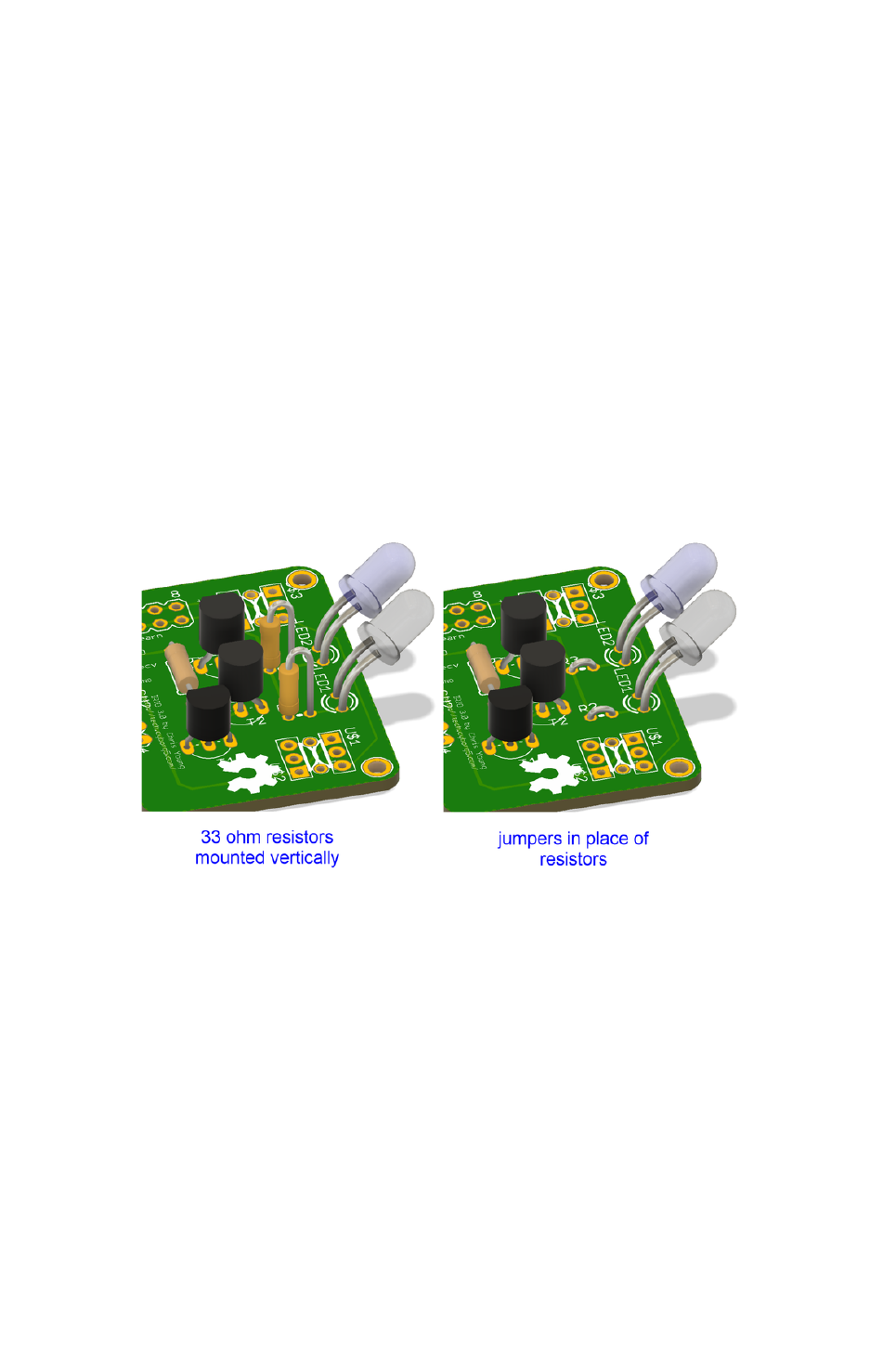
Such applications put more strain on the LEDs and the circuits than normal use as a
TV remote.
On the other hand if you are powering the board from a battery source, such as we
do in our assistive technology Ultimate Remote, the extra power that comes from
leaving out the current limiting resistors is really useful.
So you have a choice of including the resistors in positions R2 and R3 or simply
inserting a jumper wire instead. You could also install the resistors and put a jumper
or solder bridge on the backside that could be soldered or unsoldered as you
experiment.
When originally designing with this board, I wanted to make it as small as possible but
I didn't want to use surface mount components, so I decided to stand these resistors
on their end. See the image below on how to install them or watch the YouTube
tutorial video at the bottom of this page.
Receiver Configuration
If you're only using the board for output purposes, you do not need either of the two
receiver devices and you can skip their installation. If you are doing input you, will
want to use a TSOP38238 from Adafruit or a TSOP38438 from DigiKey. The latter has
slightly better automatic gain control circuitry built in, but either device will work well.
This device reads an infrared signal modulated at 38 kHz and de-modulates it into a
clean square wave so that a project can detect the patterns sent by an infrared
transmitter such as a TV remote. Most consumer electronic devices use signals
modulated at 38 kHz however some use 36 kHz, others 40 kHz and a very few use 56
or 57 kHz. Although this device is tuned to receive at 38 kHz, it will typically read 36
or 40 kHz signals quite well. Typically it cannot read higher frequency signals such as
56 or 57 kHz. You can purchase other types of TSOP devices that are specifically
©Adafruit Industries Page 8 of 17

tuned to the frequency you are using but we feel that the 38 kHz variety provides a
good compromise.
The TSOP device cannot tell you the frequency of the incoming signal. If you're using
this device just to control something you don't really need to know the frequency.
However if you are doing analysis of an unknown protocol, you might want to know
the frequency information. This requires a different device called a TSMP58000. It
does not de-modulate the signal, it just gives the raw information. IRLib2 has sample
programs that show you how to read the frequency using the TSMP58000.
The PCB has space for both devices. The upper right corner is for the TSOP which is
described as a "receiver" and the upper left is for the TSMP which is described as a
"learner", because with the proper software, that device could be used to learn all of
the information about a particular signal.
The board has been configured in such a way that you can aim either of these
devices in any of 4 directions on either the front or the back of the board. When the
lens of the device is facing you, pin 1 is on the left. As long as you insert that pin in
one of these square pads, and place the other two pins in the adjacent round holes,
the device will operate properly.
©Adafruit Industries Page 9 of 17

Supply Voltage Options
The sending portion of the circuit consisting of the LEDs and the driving transistors
can be powered separately from the receiving portion consisting of the two receiver
chips. Either portion of the circuit can be operated at 3.3v or 5v and in most
circumstances, you will want to have them both powered at the same voltage.
However, in some cases if you have 5v available to power the LED drivers but are
using a 3.3v microcontroller such as an Adafruit Feather, you MUST supply the
receiver chips with the same voltage as your processor. They will output a signal at
whatever supply voltage you provide. So while it would be advantageous to have 5v
on the LED drivers to give you a stronger output, you cannot attach 5v to the
receivers and then connect them to a 3.3v board.
©Adafruit Industries Page 10 of 17
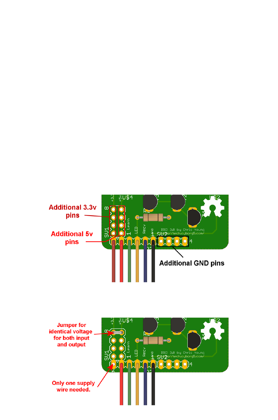
On the left side of the board there are 2 columns of supply pins. The column on the
left is labeled "+3.3v" and it is the power supply for the TSOP and TSMP devices. The
second column is labeled "+5v" and powers the transistors driving the LEDs. Both
circuits share a common ground connection.
There are three options available.
You are using a 3.3v controller and do not have 5v available to drive the LEDs so
you will use 3.3v for both.
You are using a 5v controller and will be using 5v for both parts of the circuit.
You have a 3.3v controller but 5v is available separately to drive the LEDs.
For option 1 or 2 you should jumper together the 2 power buses and connect a single
wire to either of those and supply the appropriate voltage. For option 3 you should
leave the jumper out and supply 3.3v to the left terminal and 5v to the right terminal.
This image illustrates using separate power connectors for 3.3v and 5v. It also
highlights areas where there are added additional power and ground connections you
might find useful for connecting other components to this board.
This image shows how you would jumper together the two power buses when using
the same voltage for both input and output portions of the circuit.
1.
2.
3.
©Adafruit Industries Page 11 of 17

Pinout Information
We've also attached wires to theother pins. You could however solder in headers.
As we previously explained, each of the columns of pins on the left are connected to
either the receiver chips or the LED driver circuit. On the lower right, the right-hand
most 5 pins are all ground pins.
The pin left of the ground, which has a blue wire in this illustration, is called "Recv"
and is the output from the TSOP device on the upper right portion of the board. This
pin can typically be connected to any digital input pin on your Arduino, however, it is
most useful when connected to a pin that can handle pin change interrupts.
To the left of that is a yellow wire marked LED. It drives both LEDs through the driver
transistors. This pin has to connect to a PWM pin on your Arduino. There is
information in IRLib instructions about which pins can be used for various popular
boards.
To the left of that, there is a green wire connected to a pin label "Learn". It connects to
the TSMP58000 in the upper left portion of the board. It can be connected to any
digital input pin, but it must support pin change interrupts. Again, more details and be
found in the IRLib documentation.
The YouTube video below will walk you through this entire construction project.
Using the Device
Installing Software
Of course you are free to develop your own software to use with this board. However,
it was specifically designed for use with IRLib2 which is available on GitHub by
clicking the green button below.
IRLib2 on GitHub
https://adafru.it/vwF
That library cannot be installed using the Arduino Library Manager. You have to install
manually. Installation of the IRLib2 library is as follows:
Visit the IRLib2 page on GitHib(https://adafru.it/vwF).1.
©Adafruit Industries Page 12 of 17

Select the “Download ZIP” button, or simply click this link(https://adafru.it/vxa)
to download directly.
Uncompress the ZIP file after it’s finished downloading.
The resulting folder should be named "IRLib2-master" and will contain 5
separate folders. That is because IRLib 2.x is actually a collection of 5 libraries
that work together. Sometimes in Windows you’ll get an intermediate-level
folder and need to move things around.
Copy all five folders into your Arduino library folder alongside your other
Arduino libraries, typically in your (home folder)/Documents/Arduino/Libraries
folder. Libraries should not be installed alongside the Arduino application itself.
Re-start the Arduino IDE if it’s currently running
This repository consists of a total of five libraries each of which must be in your
arduino/libraries/ folder. So for example it should be installed as follows…
arduino/libraries/IRLib2
arduino/libraries/IRLibFreq
arduino/libraries/IRLibProtocols
arduino/libraries/IRLibRecv
arduino/libraries/IRLibRecvPCI
Do not install them in a single folder such as this…
arduino/libraries/IRLib2_master
IRLib2
IRLibFreq
IRLibProtocols
IRLibRecv
IRLibRecvPCI
Here is a tutorial(https://adafru.it/m3e)that walks through the process of manually
installing libraries that are not available through the library manager.
After you have installed the library, look in the IRLib2/manuals folder. You will find an
extensive set of documentation for the library in EPUB e-book format, PDF format, and
Microsoft Word .docx format. Section 2 of that manual is a tutorial on the basic use of
the library. Below you will find some brief explanation of how to use a board but for
complete details you should really use the examples in section 2 of the IRLib manual.
2.
3.
4.
5.
6.
•
•
•
•
•
•
◦
◦
◦
◦
◦
©Adafruit Industries Page 13 of 17

Receiving Example
Start by connecting your "Recv" pin on the IR breakout board to a pin on your Arduino
that is capable of handling pin change interrupts. Load the dump.ino example from
the examples folder and make sure that it is configured for your input pin. Upload the
program and open the serial monitor.
Then point a TV remote or other infrared remote control at your board and press a
button.
Here is an example of what I saw when I pushed the play button on the remote for my
Sony DVD player.
Ready to receive IR signals
Decoded Sony(2): Value:58BCA Adrs:0 (20 bits)
Raw samples(42): Gap:65300
Head: m2400 s600
0:m600 s650 1:m1150 s650 2:m550 s650 3:m1200 s650
4:m1150 s700 5:m500 s700 6:m550 s650 7:m550 s650
8:m1150 s700 9:m550 s650 10:m1150 s650 11:m1200 s650
12:m1150 s650 13:m1200 s650 14:m550 s650 15:m600 s600
16:m1200 s650 17:m550 s650 18:m1200 s650 19:m550
Extent=32750
Mark min:500 max:1200
Space min:600 max:700
This tells us that it decoded the Sony protocol, which is protocol 2. A binary
representation of the code in hexadecimal is 58BCA. Some protocols also make use
of another piece of data, which we call "Address" but in this case, Sony does not use
that field. It also tells you that this is a 20 bit version of the Sony protocol. Some
protocols have varieties of different numbers of bits while others always use a fixed
number of bits.
When a signal is on, it is called a "mark". The empty interval between signals is called
a "space". After saying that it received 42 samples of marks and spaces, it says there
was a gap of 65300 µs. This is the amount of time from the previous signal to the
start of this signal. Most of the time you simply ignore that gap, although there can be
rare instances where it's useful information. Sometimes you want to know the amount
of space between frames of data.
Most protocols begin with a header which consists of an abnormally long mark and
space. In this case it had a mark of 2400 and a space of 600. Next comes the actual
data bits, each consisting of a mark and a space. The timing values for these marks
and spaces are given. Note that bit 0 has 600, 650 followed by bit 1 which has a mark
©Adafruit Industries Page 14 of 17

of 1150 and a space of 650. If you look at each bit, some have marks and spaces that
are nearly equal to one another while others have marks which are approximately
twice the normal value but spaces that are still in the range of 600 or so. Interpret
each of those long marks as being a binary "1" and each of them with nearly equal
length marks and spaces as a binary "0". If you do the math and convert them to
hexadecimal you will get the value 58BCA which is what is reported.
This means that hexadecimal value is a compact or encoded way of representing all
of that timing data. You can then use that hex value to later re-create the same signal
because we know how the Sony protocol works. While Sony encodes its bits using a
long marks and equal length spaces, most protocols are the opposite and use
constant marks and variable length spaces. And again, other protocols use even more
complicated systems of representing zeros and ones that are not quite as easy to
interpret by just looking at the numbers.
After all of the data bits have been printed, it also prints some other information that
can be useful in analyzing unknown protocols.
Sending Examples
Load up record.ino example program from the IRLib2/examples folder. It will do most
sending and receiving, so make sure that you have your LED pin connected to an
appropriate PWM output pin and your Recv pin connected to an appropriate input pin.
Compile and upload the sketch and open the Arduino IDE serial monitor.
Point a remote control device and hit a button. It will record the signal. Then, anytime
you send a character to the serial monitor, it will replay that signal. Here is a sample
where I pointed the control for my Samsung TV that uses the NECx protocol.
Send a code from your remote and we will record it.
Type any character and press enter. We will send the recorded code.
Type 'r' special repeat sequence.
Received NECx Value:0xE0E0F00F
Sent NECx Value:0xE0E0F00F
Every time I enter a character into the serial monitor and press enter, it would turn the
TV off and on.
If you have an additional TSOP device and connect it to another Arduino, you could
run the dump example on the second Arduino and this example on the first one. You
would see that it is transmitting the same thing that you initially sent. If you have 2
Arduino's: one set up to send in the other to receive, it is recommended you try out
the pattern.ino example. It sends a pattern of bits on a variety of protocols - you
©Adafruit Industries Page 15 of 17

should see the same thing on the receiving end as you did on the sending end. Note,
however, that some of these protocols run at 57 kHz and your TSOP device may not
be able to read them. Specifically, the third example of protocol 3 which uses 57 kHz
as well as protocol 5 which also uses 57 kHz.
Frequency Detection
As mentioned previously, the TSMP58000 device is used to measure the frequency
of a received signal. Check out the freq and dumpFreq examples in IRLib2/examples
folder as well as section "2.2.7 Advanced Receiving Examples" in the users manual for
IRLib2.
The documentation IRLib2 is quite extensive and are more examples in the examples
as well as in the documentation. You can find lots of answers your questions there.
Downloads
Once again here are the GitHub repositories mentioned in this tutorial.
IRIO3 Infrared Send and Receive Breakout Board on GitHub(https://adafru.it/
FCv)
IRLib2 Library for Sending and Receiving Infrared Signals for Arduino(https://
adafru.it/vwF)
•
•
©Adafruit Industries Page 16 of 17

Schematics
©Adafruit Industries Page 17 of 17
