
1
User Manual
For
MDVR-ME
Series(Hero-ME40-04/ME41-04/ME3
2-04/ME31-08 Series)
Howen Technologies,LTD
2018-2019

2
Content
1. Overview............................................................................................................................................................... 3
2. Cautions................................................................................................................................................................ 3
2.1. Installation Environment..........................................................................................................................3
2.2. Avoid electric shock and fire...................................................................................................................3
2.3. Transport and operation..........................................................................................................................3
3. Product introduction............................................................................................................................................ 3
4. Product Specification.......................................................................................................................................... 4
5. Mainframe............................................................................................................................................................. 4
5.1. Interface..................................................................................................................................................... 4
5.2. Front panel................................................................................................................................................ 6
5.3. Rear panel................................................................................................................................................. 6
5.4. Pin definition of Audio/Video input/output port.................................................................................... 7
5.5. Pin definition of IO&Serial port for ME4004.........................................................................................7
5.6. Pin definition of IO&Serial port on 4ch MDVR.................................................................................... 8
5.7. Pin definition of IO&Serial port on 8ch MDVR.................................................................................... 9
5.8. Remote controller...................................................................................................................................10
6. Device and installation......................................................................................................................................11
6.Connect power with MDVR...............................................................................................................................12
7. System diagram.................................................................................................................................................12
8. Menu structure................................................................................................................................................... 13
9. System operations.............................................................................................................................................13
9.1. User login................................................................................................................................................ 13
9.2. Main menu...............................................................................................................................................14
9.2.1. Search.......................................................................................................................................... 15
9.2.1.1. Video Searching.............................................................................................................. 15
9.2.1.2. Log search........................................................................................................................17
9.2.1.3. Picture search..................................................................................................................17
9.2.2. System setting.............................................................................................................................18
9.2.2.1. Register info..................................................................................................................... 19
9.2.2.2. User................................................................................................................................... 19
9.2.2.3. Time setup........................................................................................................................20
9.2.2.4. Startup...............................................................................................................................21
9.2.2.5. Config................................................................................................................................ 22
9.2.2.6. Format...............................................................................................................................22
9.2.3. Record.......................................................................................................................................... 23
9.2.3.1. General............................................................................................................................. 23
9.2.3.2. Main stream..................................................................................................................... 24
9.2.3.3. Sub stream....................................................................................................................... 26
9.2.3.4. Timed recording...............................................................................................................27
9.2.3.5. Storage setting.................................................................................................................28
9.2.3.6. OSD Set............................................................................................................................29
9.2.4. Network Setting(Not available for ME40-04)......................................................................... 29
9.2.4.1. Center settings.................................................................................................................29
9.2.4.2. Local Network Setup...................................................................................................... 31
9.2.4.3. Dial settings......................................................................................................................31
9.2.4.4. WiFi settings.....................................................................................................................32
9.2.5. Alarm.............................................................................................................................................33
9.2.5.1. IO Alarm (ME40-04 supports 4 I/O ports only)...........................................................33
9.2.5.2. Speed Alarm.....................................................................................................................34
9.2.5.3. Acceleration......................................................................................................................35
9.2.5.4. Motion Detection............................................................................................................. 36
9.2.5.5. Voltage alarm................................................................................................................... 37
9.2.5.6. Serial................................................................................................................................. 37
9.2.5.7. PTZ Control......................................................................................................................38
9.2.5.8. Fatigue Driving.................................................................................................................39
9.2.6. System Info..................................................................................................................................39

3
1. Overview
This manual is the instruction manual for ME series MDVR as below:
(Hero-ME41-04, Hero-ME31-04,Hero-ME31-08,Hero-ME40-04 ect)
Please read the manual before you using the product.
The manual will be updated from time to time without prior notice.
2. Cautions
2.1. Installation Environment
1. To extend equipment life, please install the equipment in locations with little vibration.
2. To ensure normal heat dissipation, do not install the device in a poorly-ventilated area (such as
trunk), and also keep about 15 cm away from other objects on the same level.
3.The device shall be horizontally installed and protected against water, humidity and lightning; in
addition, keep the vehicle still during installation to prevent damage to the device due to falling off.
4. To ensure safe operation, keep the device, camera, cables and other accessories out of reach of
passengers and driver.
2.2. Avoid electric shock and fire
1. The machine uses 8V-36V DC power supply, notice the polarity when wiring to avoid short circuits.
2. Please power off the device when connecting accessories with device.
3. Do not touch the power and the device with wet hands.
4. Do not spray liquid on the device to prevent internal short circuit or fire.
5. Do not put any other equipment on top of camera.
6. Do not disassemble the housing without authorization to avoid damage or electric shock.
2.3. Transport and operation
1. Please use the original package in transport to avoid damage in transport.
2. Please keep power off in moving the device or replacing components.
3. Product introduction
The 4CH&8CH MDVR supports 4/8 channels analog audio and video recording and playback with
network function.
The product adopts ARM DSP fast dual-core processor running on the Linux embedded OS, and also
integrates the most advanced H.264 video encoding/decoding in IT industry, 3G/4G network, GPS and
Wi-Fi, as well as power-failure protection, HDD shock absorption, HDD heating, wide voltage features.
It is extensively applied in public buses, logistics vehicles, school buses, police cars, financial convoy
cars and fuel tankers.
Main Features:
Supports 4/8 ch AHD 720P/ 1080P cameras
Industry leading CPU with powerful processing ability
Supports HDD/SSD/SD CARD for recording. Max. 2TB HDD.
“Plug and Recording” Hard disk: innovative hard disk mounting design, no need to mount screws
Robust design: Cast aluminum enclosure. Patented design
Selected industrial power chip-sets, support 8-36V wide range power input, adapt to harsh
environment
Support UPS
Support low/high temperature environment
Support external Fireproof box, to backup data in extreme scenarios
Support backup recording
Dual streams for local recording and network transmission
Support 3G/4G, Wi-Fi, GPS modules.
Built-in G-sensor for harsh acceleration/deceleration detection

4
Data self-protection, save data when shut down abnormally
4. Product Specification
Power input
DC:
+8V ~ +36V
8V~36V, Check the supply voltage of the vehicle
battery before use; If it is supplied with more than
36V for a prolonged period, the device may be
damaged.
Power output
[email protected],+5V@2A
ACC detection
≤4V
Power off
≥5V
Power on
Video input impedance
75Ω
Each video input impedance: 75Ω
Video output voltage
2Vp-p
2VP-P CVBS output analog signal which should
be adapted by 75Ω of input impedance from the
display unit.
I/O interface
<1V
Low level alarm
>5V
High level alarm
Operating temperature
-20℃~70℃
In a well-ventilated place
5. Mainframe
5.1. Interface
SD CARD type MDVR:
Hero-ME41-04

5
Hero-ME40-04
Attention :Hero-ME40-04 without 3G and WIFI function, so it need not to set the parameters in the
menu of 10.2.4 Network setting.
HDD type MDVR:
Hero-ME31-08

6
5.2. Front panel
Interface
Name
Description
IR
Infrared Receiver
HDD Slot
2.5 inch SATA HDD slot.
Please unlock the lock with the key.
You can also see SD card slot and SIM card
slot with HDD slot together.
SD card/SIM
card slot
SIM card slot;
SD Card slot;
Lock&Open
Open and lock the door for HDD/SD card/SIM
card slot;
On/off switch for device power;
USB
For USB mouse,USB flash drive,etc.
LED
LED Indicators. Green is on status. SD/HDD
LED blinking means it’s recording.Alarm
blinking means there is an alarm.
AV Out
3.5mm AV output port;
Connect with monitor;
The port will output audio and video to screen.
5.3. Rear panel
Interface
Name
Description
CH1/CH2/CH3/CH4/
CH5/CH6/CH7/CH8
Connect with cameras.
The port can provide DC12V power to
cameras directly.
AV Out
4pin aviation connector;
Connect with monitor;
The port will output audio and video to
screen.

7
3G/4G LTE
Connect with 3G/4G LTE antenna.
GPS
Connect with GPS antenna.
WIFI
Connect with WIFI antenna.
Power
Connect with power adapter/battery
LAN
Connect with network cable for network
I/O&Serial
For IO cables;
Including sensor input,sensor output,DC
power output, RS232, RS485, sensor
Extend
Extension for I/O&Serial
5.4. Pin definition of Audio/Video input/output port
5.5. Pin definition of IO&Serial port for ME4004

8
The port contains below interfaces:
DC5V OUT;
RS232;
Sensor Input;
Sensor Output;
1
2
3
4
5
6
GND
RS232-RX2
RS232-RX1
SENSOR-OUT
SENSOR-IN4
SENSOR-IN2
7
8
9
10
11
12
VCC-5V
RS232-TX2
RS232-TX1
GND
SENSOR-IN3
SENSOR-IN1
5.6. Pin definition of IO&Serial port on 4CH MDVR
The port contains below interfaces:
DC12V OUT;
DC5V OUT;
RS232;
RS485;
Sensor Input;
Sensor Output;
Video Out;
Audio Out;
Speed pulse;
MIC;
Hero-ME41-04
1
2
3
4
5
6
7
8
9
10
11
12
13
14
15
VCC12V
-OUT
GND
RS232-
RX1-De
bug
RS232-
TX1-De
bug
Speed-A
SENSO
R-IN-6
RS485-
B3
RS232-
RX2
SENSO
R-IN-9
SNESO
R-OUT-
1
SENSO
R-IN-3
GND
VIDEO-
OUT
MIC-
RS232-
TX1
16
17
18
19
20
21
22
23
24
25
26
27
28
29
30
VCC5V-
OUT
GND
GND
Speed-B
SENSO
R-IN-7
SENSO
R-OUT-
2
RS485-
A3
RS232-
TX2
SENSO
R-IN-5
SNESO
R-IN-4
SNESO
R-IN-2
SENSO
R-IN-1
AUDIO-
OUT
MIC+
RS232-
RX1

9
5.7. Pin definition of IO&Serial port on 8ch MDVR
Hero-ME31-08
IO&Serial
The port contains below interfaces:
DC12V OUT;
DC5V OUT;
RS232;
RS485;
Sensor Input;
Sensor Output;
1
2
3
4
5
6
7
8
9
10
11
12
VCC5V-
OUT
GND
RS232-
RX4
RS232-
TX4
SENSOR
-IN-8
SENSOR
-IN-7
SENSOR
-IN-6
SENSOR
-IN-5
SENSOR
-IN-4
SNESOR
-IN-3
SENSOR
-IN-2
SENSOR
-IN-1
13
14
15
16
17
18
19
20
21
22
23
24
RS232-
TX2
RS232-
RX2
GND
RS232-
B3
RS232-
A3
GND
SENSOR
-OUT-2
SNESOR
-OUT-1
GND
12V
Extend
The port contains below interfaces:
DC12V OUT;
DC5V OUT;
MIC;
Audio Out;
CAN BUS;
USB ;
VGA;
1
2
3
4
5
6
7
8
MIC+
GND
CAN-H1
CAN-L1
GND
USB-DP
USB-DM
5V
9
10
11
12
13
14
15
16
12V
GND+GND
AOUT
VGA-HS
VGA-VS
VGA-B
VGA-G
VGA-R

10
5.8. Remote controller
Login
When the recorder is set with a password, press the Login key to input
your password. As the system is not provided with recover and reset
features, always keep your password in mind.
INFO key
Short-cut for check the device’s information.
Quad View key
Number key 1, 2, 3,
4
On the monitoring interface, used to switch between quad view and single
view; press the Quad View key to display 4 screens. You can press
number 1/2/3/4 to display channel 1, channel 2, and channel 3 and
channel respectively.
Return key
Return to the previous menu, and finally exit from the setup menu to the
monitoring interface.
DEL key
Delete when input the numbers by remote.
PAUSE/STEP key
Used to pause playing or play images at a single step. Press the key again
to recover normal play speed.
Frame key
Press this key to play a video in a frame rate.
Play key
Press this key to start playing (search the video file to be played and
select, then press the key to play it).
FWD key
Forward key in four grades: 2X,4X,8X,16X

11
REW key
Rewind key in four grades: 2X,4X,8X,16X
NEXT key
Page down or roll to the next file.
PREV key
Page up or roll to the previous file.
PTZ key
Auto, preset, call, zoom +, zoom -, focus +, focus -, aperture +, aperture -,
PTZ, PRESET, RECALL, BRUSH.
F1, F2, F3
F1 is a key to start functional test
6. Device and installation
Take ME31-08 HDD/SD for example , the other models’ operation are same.
1. Unlock the electric lock on front panel
Hero-ME31-08
2. Install disk
Just need to plug the disk and close the cover.
Notice the direction of disk.
3. Install SIM card and SD card.
Install SIM card and SD CARD.
4. Lock the electric lock.
5. Connect 3G/WIFI/GPS antennas
Connect 3G/WIFI/GPS antennas according to labels on antennas and connectors.

12
6.Connect power with MDVR
Use DC12V, 3A(at least) or higher(5A is better) power adapter in office test.
As for vehicle installation, please connect ACC cable with ignition on vehicle.
7. Connect TFT monitor
Connect a TFT monitor with AVOUT port on the rear panel of MDVR.
Attention:The MDVR will provide power and image to TFT screen by Avout port, so don’t connect
any external power for the TFT screen, or else, it will destroy the MDVR.
7. System diagram
This product is suitable for video monitoring or remote monitoring and applicable for general or special
vehicles. It mainly uses the special designed vehicle camera to acquire the front video signal, then
transmits the signal via a special video cable to the MDVR mainframe for video compression and image
processing and finally stored in the HDD.
It can also locate where the vehicle is in real time via GPS module, and then upload the location
information to the remote server via 3G/4G module. You can download video files from the remote client
to realize real-time remote monitoring of the vehicle. The following shows the actual application model
of this product that may be different depending on vehicle type and peripherals.

13
For Hero-ME40-04,the structure is simple .It is only for recording on the device ,without the network
(3G/4G, WIFI) , so it will not transmit the data to server .You can play on the device directly or by MDVR
player(get the map information and video) .
8. Menu structure
9. System operations
9.1. User login
New Firmware :For all devices, the default password for admin is 111111; user is 666666
Old Firmware:
The default admin password for ME31-08 is 666666.

14
The default admin password for ME41-04,ME32-04 is 111111.
With remote:
Press 【LOGIN】button to login MDVR.
Press【Enter】button to call the keyboard page to input password.
If any err while inputting ,press【Delete】button to delete.
With USB mouse:
Please connect a USB mouse with MDVR to setup the menu.
Right click on the live video interface and you can see the login page.
Click on the password column to call the keyboard page to input password.
9.2. Main menu
15
9.2.1. Search
Searching menu includes: video search, log search and image search.
9.2.1.1. Video Searching
Date:Press number keys on remote to select the date, it defaults for the current day.

16
Start time:Press number keys to input the time, it defaults for 00:00.
End time:press number keys to input the time, it defaults for 23:59.
Video Type:press 【Enter】to select:
REC-ALL (all type of videos)
REC- ALM(alarm videos) contains
IO( I/O recording), G sensor, Speed ,Move, Fatigue,OCC type. Need set in the Alarm menu first.
Disk Type:press【Enter】to select: main disk / mirror disk / disk backup. it defaults for main disk.
Regarding the difference , please check [9.2.3.5 Storage setting].
Search:Move to the "Search" button,press【Enter】, then enter the search results interface.
The interface contains record date, the current page number , menu for browsing, search
contents.
In the search contents, it contains : DISK(the file’s location), Type (which you have selected) ,start
and end time.
Press the Arrow keys to select the information you want to view, press【Play】on the remote or click
PLAY to start playing the video, press the【Return】key to return the previous level.
Select the video file you want to view and press【Enter】key to check the video to be backed up.
Press the Arrow keys to select "First", "Previous", "Next", "Last", "Play", press 【Enter】key to
display the information page.

17
Export: Press【Enter】, the selected videos will be exported to an external USB storage device .
Note: If the selected period there is no video file and interface prompt: "! This day has no video
file’’
9.2.1.2. Log search
Log management record : power on/off, GPS timing, alarm event information, including event date,
event time, and event name.
Date Search: Press number keys on remote to enter the date, default setting is today.
Log Type: Press【Enter】to select: All log/ System log /Configuration log/ Alarm log / Record
log/Clear log/Operation log/Manage log. Default is all log.
Start Time: Press the number keys to enter the time, default is 00:00.
End Time: Press the number keys to enter the time, default is 23:59.
Search: Press【Enter】to select, search the log information from the start time to the end time.
Press the arrow keys to select "First", "Previous", "Next", "Last", press【Enter】to display the
information page.
9.2.1.3. Picture search
Pic search is used for checking the snapshot when alarm is triggering( I/O alarm ,Video detect )
, should set in the alarm menu first.

18
Search Date: Press number keys to enter the date, default is today.
Start Time: Press the number keys to enter the time, default is 00:00.
End time: Press the number keys to enter the time, default is 23:59.
Search: Press【Enter】to select, search the log information from the start time to the end time.
Press the arrow keys to select "First", "Previous", "Next", "Last", press 【Enter】 key to display
the information page.
Export: Press【Enter】, the selected pictures will be exported to an external USB storage device .
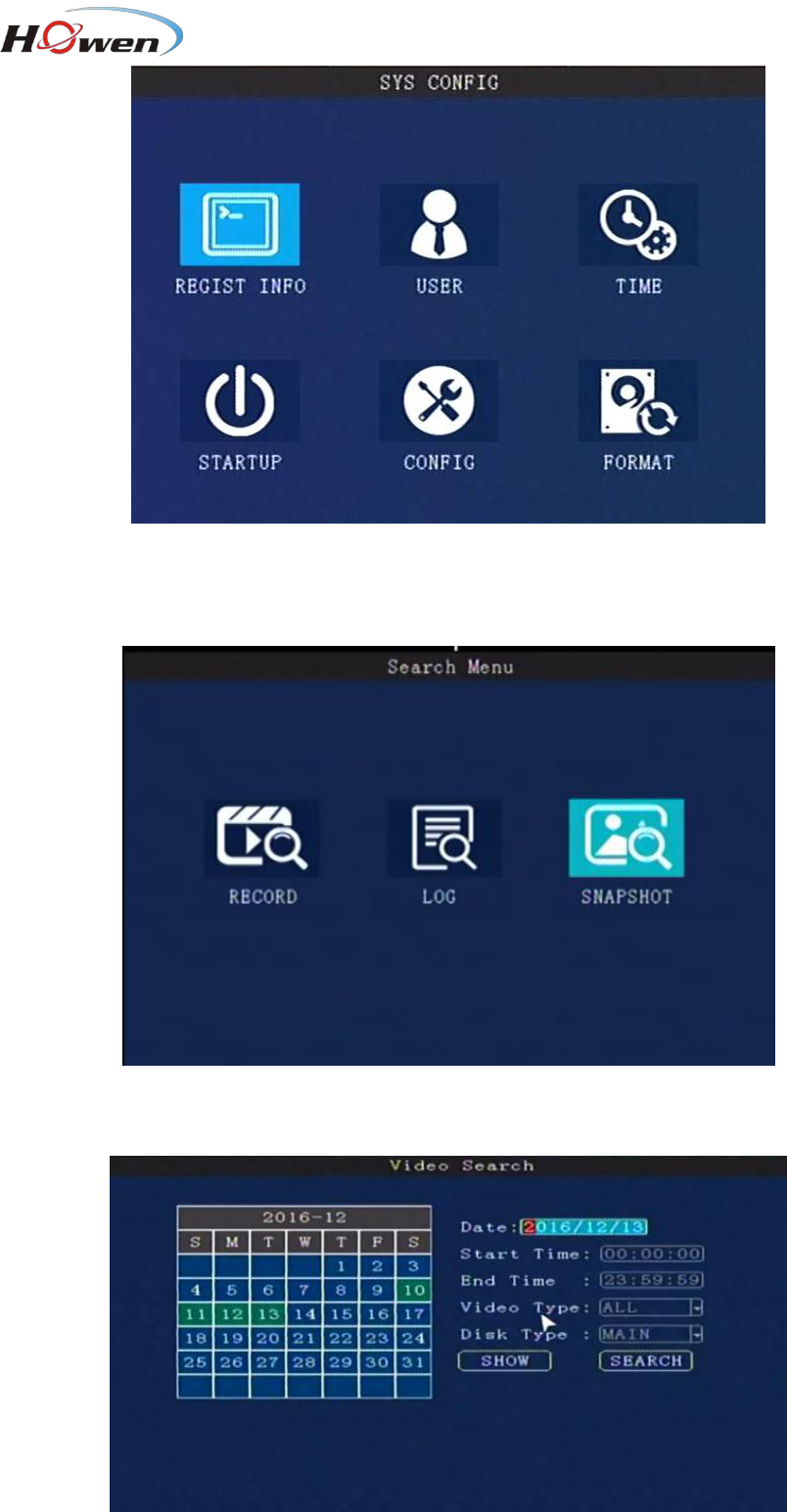
9.2.2. System setting
System setup menu includes: Register info, User, Time, Startup, Config and Format.

19
9.2.2.1. Register info
The CMS server will monitor and manage the vehicle by Device ID.
Device ID、Plate No., Province ID, Terminal Model, Factor ID, Terminal ID, City ID:Press number
keys to input.
Device ID
Set a number(12 digital at most) ,but must be unique, It’s very important , since we will add this
device to the server by these numbers.
Language: press【Enter】to select and system will reboot automatically.
Position Mode:GPS, GLONASS, BD, and so on.
License1 &2: RFID function for driver, should input the license number.
9.2.2.2. User
Password:press【Enter】:On/Off
ON: Login with Admin password can setting the User &Admin password; login by user password can
only set a user password, password must be the same with [confirm] below .

20
The administrator can set or change the parameters, so if you need to set some parameters, login
with this account.
The user can search and view the files only.
OFF: Without password. When entering the menu, get into the main menu directly .
9.2.2.3. Time setup
Date Type: Use for selecting the data type, year - month - day, day - month - year ,month - day -
years. Press【Enter】to select.
Time Sync: Press【Enter】to select: Off / GPS / NTP, default is GPS.
Time out: Setup Menu Waiting Time, once overtime, it will automatically log off the current user,back
to the monitoring mode. Press【Enter】 to select: 1 minute / 2 minutes / 5 minutes / 10 minutes,Default
is 1 minute.
Date: To modify current system date, press number keys to enter.
Time: To modify current system time, press number keys to enter.
Timezone: Press【Enter】to select a time zone, default is GMT + 08.
DST mode: Daylight Saving Time , set it according to your local area requirement.
Select the start and end time, by week and the specific hour , then set the offset time (according to
your local regulation, normally it’s 60 minutes).

21
9.2.2.4. Startup
4-channel
8-channel
Power Mode:To set Power ON/Off mode, press【Enter】to select. Acc mode / timing mode.
Timing mode: on/off according to the user’s setting period.
Acc mode: On/off by the vehicle’s ACC ignition.
Auto Reboot: ON/OFF. The default is OFF. If it’s ON, it will reboot at the Reboot Time.
If the device is running all the 24 hours, please set it ON.
Delay off: Set the device delay off time.MDVR will still work after the vehicle is power off , then turn off
after Delay-off time, press 【DEL】 to clear the current number, press the number keys to change.
1440 minutes means the device will work all the time if the battery can support that long time. So please
set a available parameter for it.
RecDelay: When the vehicle is power off, set the record delay time, it will continue recording during this
time .This time can’t exceed the Delay off time .
Record : Check the channels for delay recording.
Power on: Setup power on time under timing mode.
Power off: Setup power off time under timing mode.

22
9.2.2.5. Config
Parameters import: Import configuration information in the USB driver to the current device.
Parameters Export: Export all the configuration information of the current device to the USB flash
driver.If there is no USB flash driver, it will saved in the existed HDD/SD card.
Tips:
If you had set the whole parameters in one device already, you can export it first, and then import to
other devices by this function. After the import, it will reboot automatically.
Save User Setting: Save all configuration information for the current user, it will store this information
in the SD/HDD.
Factory settings: Restore some device parameters to factory default, such as Alarm, Record. It will
not change the Register and Network setting.
Back to User settings: Restore all device parameter setting to saved user’s setting
9.2.2.6. Format
Press the arrow keys to select DISK1 / DISK2 / USB(if you had plugged the USB driver).
It will display the whole available disks. Size/Std size/Block setting.
STD size: The area for saving Alarm pictures, debug Logs, system file, Alarm videos. This area is which
23
you can check on the PC. For example, if you need more space for saving alarm videos and upload to
FTP server, should change it . Just input a new value in StdPart(GB) and SAVE it.
Block(MB): All videos are saving by block read&write technology. It’s not recording by time length. So if
you need save a long time period video, change a bigger value for it.
Format: If there is some err with the disk, format it. It will take about some minutes.
Besides, you can also evaluate the disk space for recording.
9.2.3. Record
Recording setup including:General, M-stream, S-stream, Time recording, Storage, OSD set.
9.2.3.1. General
4-channel
8-channel
24
The General info contains the basic setting for camera. When you install the MDVR, please
double-check these sub-menu .
TV System: Press【Enter】to select: PAL / NTSC, default is PAL. If it’s wrong ,the image will become
black-white color only. Select PAL/NTSC according to the camera’s video type. Device will
automatically restart after changing it.
Camera Type: Press【Enter】 to select:
4-channel :4 ×720P, 2 ×720P+2 ×D1,4 ×D1/8 ×D1
8-channel: 8*1080p, 8*720p,4*1080p+4*D1, 4*720P+4*D1, 2*1080P+6*720P and so on.
Resolution : D1:720*576, 720P: 1280*720 . Set it according to the camera type.
Generally speaking, 2MP is 1080P, 1MP is 720P mode, D1 definition is less than 1MP.
Attention: this setting must be same with cameras, or else , it will not display video.
For example: You have 4*1080P and 4*D1 cameras , choose item,
You must put the 1080P in channel 1/2/3/4, put D1 in channel 5/6/7/8.
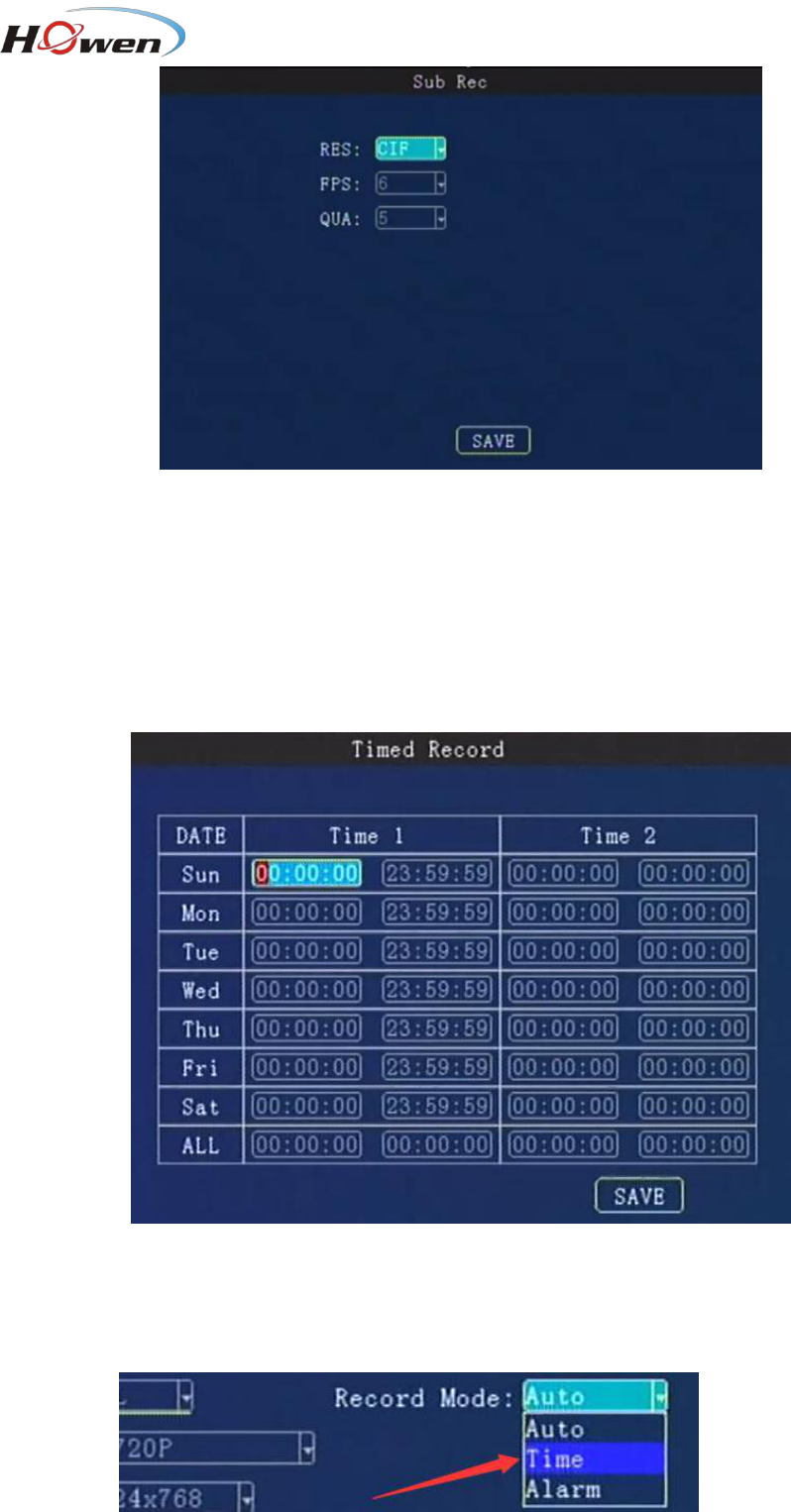
Record Mode: Press【Enter】 to select: Auto / time recording / alarm recording, default is Auto.
Auto: it will record all the time.
Time recording: Need set the time in [9.2.3.4 Timed Record].
Alarm: Only record when alarm is triggering, should set in the Alarm menu first.
Display Resolution: This is set the TFT screen dispaly resolution.Press 【 Enter 】 to select: 720 ×
576/1024 × 768/1280 × 720/1920*1080.
View mode: Press【Enter】to select: Two / Four / Six / nine
View Chn: Select the channels you need ,default setting is all channels.
9.2.3.2. Main stream
25
Enable: Press【Enter】to select: On / Off.
Res: Resolution ,press【Enter】to select: D1 / HD1 / CIF / 720P.
CIF:352*288,HD1:352*576, D1:704*576, 720P:1280*720 .
FPS: Frames per second , More frames, every picture will be more clear. press【Enter】to select: 1-25 .
NTSC : 30FPS , PAL: 25FPS.
QUA: Quality of the video, press【Enter】to select: 1-8. 1 is best , but it will cost more storage space.
AUDIO: Press【Enter】to select: On / Off. ON means the audio will be saved with video together.
Mirror/Flip: Set the image to mirror or flip .Press【Enter】to select the types.
QuickSet: Setup all channels resolution simultaneously, press【Enter】to select: 720P/D1 / HD1 /
CIF / 720P.
IPC test:
ME31-08 supports 4 IPC by a PON switch.
ME41-04,ME32-04 supports 1 IPC camera.
We will provide special manual about this.
Attention: Please keep the EN menu as OFF if there is no IPC.

26
Storage Calculation
MDVR support dual streams.
Main stream is mainly used for local recording; Sub-stream is mainly used for network transmit.
Main stream:
Resolution
Image
Quality
Level
1
2
3
4
5
6
7
8
Bitrate
[Kbps]
1080P
8192
7168
6144
5120
4096
3072
2048
1536
720P
4096
3584
3072
2560
2048
1536
1024
800
D1
2048
1536
1230
1024
900
800
720
640
HD1
1280
960
768
640
560
500
450
400
CIF
800
600
480
400
350
312
280
250
Resolution
Image
Quality
Level
1
2
3
4
5
6
7
8
Bitrate
[MB/hour]
1080P
3600
3150
2700
2250
1800
1350
900
675
720P
1800
1575
1350
1125
900
675
450
351
D1
900
675
540
450
395
351
316
281
HD1
562
422
337
281
246
219
198
176
CIF
351
264
211
176
153
137
123
110
Sub stream:
Resolution
Image
Quality
Level
1
2
3
4
5
6
7
8
Bitrate
[Kbps]
D1
1500
1300
1100
900
800
700
600
500
HD1
1300
1200
1000
800
700
600
500
400
CIF
512
450
400
350
320
280
250
220
Resolution
Image
Quality
Level
1
2
3
4
5
6
7
8
Bitrate
[MB/hour]
D1
659
571
483
395
351
307
264
219
HD1
571
527
439
351
307
264
219
176
CIF
225
198
176
153
140
123
109
96
Now take the Main-stream(Sub-stream is used for uploading)table for example.
It is an approximate data for one camera in one hour, eg. 720P, if the Quality is 1 (best), from the table,
we know it will take up 1800MB /hour.
Take ME41-04 for example, suppose it has 4 cameras, and work 10 hours everyday in one month (30
days).
Total= 1800MB*4(cameras)*10(hours)* 30(days)=2160000MB ≈ 2109GB. And you need a 2TB HDD at
least.
9.2.3.3. Sub stream
27
The sub-stream is used for live streaming. The higher Resolution, bit rate and frame rate, video will be
more clearer, but need more 3G/4G data.
Notice:
1. Currently 3G networks only support CIF real-time network transmission, the default setting is CIF
and fixed.
2. QUA, 1 is best, for saving the 3G/4G data. Please choose 7 or 8.
9.2.3.4. Timed recording
Setting the start time and end time of timing record, press number keys to enter.
During the setting time, it will start recording automatically.
Attention:
1. Need turn on the Time mode first,
2.Set the ALL as 00:00:00-00:00:00
3. Set the recording plan for every day.

28
9.2.3.5. Storage setting
Alarm Previous Rec: Set the previous recording time before the alarm happens. Press number keys to
enter, 0 to 60 seconds for selection.
Alarm delay:Set the delay recording time after the alarm happened. Press number keys to enter, 0 to
3600 seconds for selection.
Alarm file to server: Alarm file save to CMS or FTP. All alarms file will be uploaded at real-time. So pay
attention if it’s linked by 3G/4G, since it will cost data of SIM card.
CMS is default setting, it will be saved in the Storage Server of CMS.
FTP: It will upload to the FTP server of CMS or your own FTP server(need build it first).
Alarm file protection: Set the alarm file protection time, this files will be not deleted during the setting
days. Press number keys to enter, 0 to 45 days.
Protect Switch: Close or Open.When it’s open, then you can set the Alarm file protection’s days(it
will not be covered in HDD/SD until that days). And select the alarm type , such as I/O ,G-sensor ,speed,
Fatigue ,voltage and so on.
Attention
: In order to upload files to FTP or CMS storage server.
1. Must turn on the Protect Switch OPEN. And set the Alarm file protection days.
2. Set a Big space for StdPart (such as 2G/4G size) in 9.2.2.6 Format.
Disk and Usage: Press【Enter】to select: No / Record / mirror / Backup.
No: No recording; Record: Recording the file in this disk.
Mirror: Save the recording video in this disk at same time.
Backup: When the current recording disk is failed, the system will save the video in this disk.

29
9.2.3.6. OSD Set
Set the stamp information on the image , and location to be displayed on the image.
Time: Press【Enter】 to select Enable: on / off, press number keys to enter the X and Y coordinates.
Plate: Press【Enter】 to select Enable: on / off, press number keys to enter the X and Y coordinates.
GPS: Press 【Enter】 to select Enable: on / off, press number keys to enter the X and Y coordinates.
USR DEF: Press【Enter】to select Enable: on / off, press number keys to enter the X and Y coordinates.
USER Define: You can define every channel a name by yourself, press【Enter】to call out the keyboard,
and input the characters ,12 characters at most.
9.2.4. Network Setting(Not available for ME40-04)
Network Setup menu includes: Center settings, Local settings, Dial settings and WiFi settings.
The device access the CMS server or third party platform by these method .
Network priority is WIFI>3G/4G>LAN, it will switch automatically according to the network status.
9.2.4.1. Center settings

30
Our MDVR supports 2 system platform at the same time. You can choose one of them to test.
Server1: CMS platform. Input your CMS server PC’s WAN or LAN IP address for test. Port: The
default port is 6608
Server 2: The third party server address. Such as FMS platform.
Server3/4 : Transport server. For uploading the raw data of external devices via RS232 or RS485.
Server Protocol: It’s the protocol used to connect the center server.
For server1 protocol: T-protocol is default setting .Don’t change it!
For server2 protocol : It contains H-protocol ,R-protocol, Transpt, etc. .H-protocol is Howen protocol
(our own protocol) if you need to link the third party FMS platform.
GPS Interval: The time interval for sending the GPS data package(contains GPS, speed,
alarm ,time&date and so on. The device will send the data package to platform.
If you need save the data of SIM card, set a long time.
FTP server
Input the FTP server IP address, port .User and password. You can build your own FTP server.
StatePort is for maintenance(still under development).
If you have set in 9.2.3.5 Storage setting and choose the FTP, all alarms file will be uploaded to FTP
server.
For FTP : IP is CMSserver’s WAN IP address. Port: 2121
User: admin Password: cmsserverv6

31
9.2.4.2. Local Network Setup
Local network IP
LAN is used for local connection or IPC connect.
The device supports LAN connect directly like as your PC. Set the same IP segment with your PC ’s
address(include IP, Mask, Gate, DNS address. For MAC, just use our default setting address,don’t
change), otherwise, it can not be connected. The LAN indicator will be lit. If your don’t know this
information, ask for your ISP supplier or IT team for help.
When connect the IPC camera, make sure the IPC’s address in the same segment with LAN. For
example, if the LAN address 192.168.1.010, the IPC address could be 192.168.1.100, they are in the
same 192.168.1.xxx segment. Or else, it can not link the IPC.
9.2.4.3. Dial settings
Enable: Press【Enter】to select: On / Off.
Net Type: Press【Enter】to select: WCDMA / EVDO / TD-SCDMA / TDDLTE / TDDLTE-1 / TDDLTE-2.
APN.: Set for access the internet, it will not transmit the video if set wrong .
Notice: Each telecom supplier has a different APN , please ask the local supplier first.
32
Center No. : Default setting is *99#. Please inquiry your supplier if any change.
User name, Password: set up a 3G/4G service user name and password. Also should inquiry your
SIM card supplier!
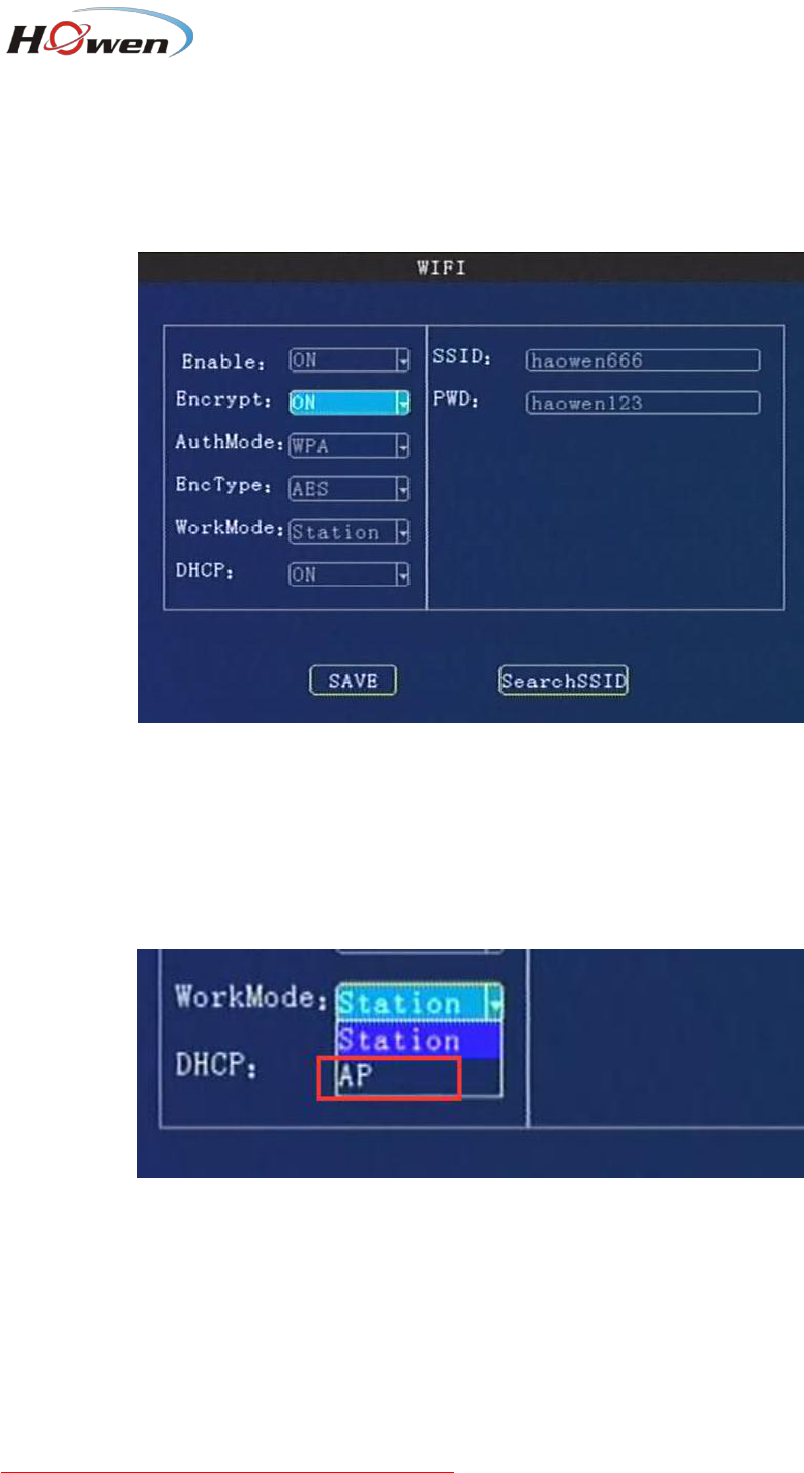
9.2.4.4. WiFi settings
WIFI Enabled: Press【Enter】to select: On / Off.
Enable Encryption: Press【Enter】to select: On / Off.
Authentication Mode: Press【Enter】to select: Open / Shared / WPA / WPA-PSK.
Encryption Type: Press【Enter】to select: NONE /WEP/ TKIP / AES.
Work Mode:Station or AP. Station is default setting ,which enable the device link the internet or router ‘s
wireless signal.
AP: Access point mode, the device will share a hot-spot for other devices .
Besides, user can set the parameters by our APP or mobile checker.
DHCP: Dynamic Host Configuration Protocol. OFF: Input the IP address manually. ON: Get the IP
address automatically.
SSID, password : Input your own router’s wireless signal name and password.You can click Search
SSID.
IP, Gate, Mask : If the DHCP is off, you need to set this manually.
WIFI IP segment should be different with LAN IP.

33
9.2.5. Alarm
Alarms include: I/O alarm, speed alarm, G-sensor, motion detection, alarm voltage, Fatigue,serial
port and PTZ control management.
9.2.5.1. IO Alarm (ME40-04 supports 4 I/O ports only)
IN1-IN6 is for generally use (same with the I/O serials cable ), IN7 and IN8 are for iButton, it must be
OFF status if you don’t use them. (on I/O serials cable , it is IN7 and IN9)
Enable: Press【Enter】 key to select: off / emergency / front door / middle door / back door / driver door
/ other doors / low beam light / high beam light / turn right light / turn left light / brake / back / Customer
definition(Press Info key to call out the keyboard for new firmware).
Level: Press 【Enter】to select: high / low.
High means it will trigger sensor alarm when the voltage of sensor input is changed from 0 to a high
voltage[DC 4V - 12V].
Low means it will trigger sensor alarm when the voltage of sensor input falls from a high voltage[DC
4-12V] to 0 .
Delay: The alarm duration time after trigger source is removed, it is used for setting linkage’s duration
time. During this period, it will not response the new alarm if there is a continuous triggering on the I/O
port.

34
Wait: The waiting time for trigger in case of mistaken touch.
Record: Press【Enter】 to select: On / Off, enable when the alarm happens, it will record or not.
Linkage: Press【Enter】to select: OFF/Output 1 / Output 2 / Buzzer/snap-up.
Output1:Output1 cable will output a DC12V voltage when alarm is triggered.
Output2:Output2 cable will output a DC12V voltage when alarm is triggered.
Buzzer:Need PCB support this component.
Snap-up: It will capture the picture while alarm is triggering . And save in the SD/HDD.
Preview: Press 【 Enter 】 to select the channel. When the alarms happen, it will pop-up the setting
channel ‘s image on the TFT screen .
Tips: How to rename the I/0?
1. Navigate to this blank option.
2. Press【Enter】 on the remote to confirm.
3. Press【INFO】 key on the remote, it will pop-up keyboard interface.
4. Input a new name.
5. Save it.
9.2.5.2. Speed Alarm

35
It contains Parking(parking time setting), L-Warn(low-speed warning), L-ALM(low-speed alarm),
H-Warn(high-speed warning), H-ALM(high-speed alarm), Spd Up(speed up) ,Spd Down(speed down)
these seven items.
Set the parameters refer to the following text. When it break the rule ,it will trigger an alarm.
For example , L-ALM(low-speed alarm), set it ON and the Limit value and other settings. If the vehicle
run a speed lower than the Limit value , it will trigger the alarm.
Enable: Press【Enter】to select: On / Off.
Limit: Set a speed value for system judgement.
Delay:Linkage’s duration time. Press number keys to set. During this period, it will not response the
new alarm if there is a continuous triggering.
Wait: The waiting time in case of mistaken judgement or just wait.Press number keys to set.
Record: Turn on/off recording function.Press【Enter】to select: On / Off.
Alarm link: Press【Enter】key to select: OFF / Output 1 / Output 2/Buzzer.
Speed Source: Press【Enter】to select: GPS / Vehicle / Mix.
Pulse: Access through SPEED-A, SPEED-B operator to take the pulse factor. This function need
external pulse sensor device.
Speed unit: km/h, MPH, nm/h for option.
For Parking, the Limit is also speed, you need set a speed first, if the vehicle under this speed, the
device will deem it’s parking.
For speed up/down, set a value for it. If the vehicle harsh-accelerate or harsh-brake, the system will
compare the current speed with the previous second’s speed all the time. If the change value more than
the setting parameter, It will trigger an alarm.
9.2.5.3. Acceleration

36
The acceleration alarm first need to get coordinate correction, the vehicle may be parked on level ground
to clear calibration.
Tilt: it refers to a device rollover angle, unit is degree.
Enable:Press【Enter】to select: ON/OFF.
Limit: Set a limited value for system judgement.Press the number keys to enter.
Wait : The waiting time in case of mistaken judgement . Press the number keys to enter.
Record: Turn on/off recording function.Press【Enter】to select: On / Off.
Alarm link: Press【Enter】to select: OFF / Output 1 / Output 2/Buzzer.
Delay:Linkage’s duration time. Press number keys to set.
Adjust: After you install the device, press this button to refresh all parameters to zero.
9.2.5.4. Motion Detection
For saving the space of the disk, you can turn on the motion-detect or function. It will record only when
camera has detected the movement objects or actions.
Besides, it also supports Occlusion alarm function. You can only choose one of them between Motion
detect and video Occlusion one time.

37
Enable:Press【Enter】 select: ON/MOVE/OCC.
Limit: Set the threshold of video area/detection area percentage . Suggest 45.
Sense: Sensitivity , it decides the detection sensitivity level .Press【Enter】 to select: 1-8.
1 is the highest level. Suggest to use 3.
Record: Turn on/off recording function.Press【Enter】to select: On / Off.
Alarm linkage: Press【Enter】to select: OFF/Output 1 / Output 2 / Buzzer/snap-up.
Delay:Linkage’s duration time. Press number keys to set.
Attention:
Regarding the occlusion function. For 8-channel device, we suggest choose 4 channels at most.
For 4-channel device, we suggest choose 2 channels at most.
9.2.5.5. Voltage alarm
If the operation voltage is low, it will trigger the alarm. The system can work at 8-36V (The lower voltage,
the more current demanding), it’s better work at 12/24V. So you can set a Limit value first.
Enable:Press【Enter】to select: ON/OFF.
Limit: Set the threshold of voltage level .Press the number keys to enter.
Wait: The waiting time in case of system mistaken detection . Press the number keys to enter.
Alarm linkage: Press【Enter】key to select: OFF / Output 1 / Output 2/Buzzer.
Delay:Linkage’s duration time. Press number keys to set.
9.2.5.6. Serial

38
Com port means the RS232 and RS485 communication ports, it’s used for connecting the accessory,
such as fuel level detection, IC card reader, fatigue driving camera, people counting etc.
For 4-channel device, COM1 & COM3 is RS232 ,COM2 & COM4 is RS485; For ME40-04, it supports
RS232 only .
For 8-channel device, COM1 & COM2 is RS232, COM3 is RS485.
Attention:COM1 is for RX1/TX1, COM3 is for RX2/TX2.
For different external device, the setting is different. We will provide the corresponding installation
manual for reference.
External: Press【Enter】to select accessory type.
Baud Rate: Press【Enter】to select: 600/1200/1800/2400/4800/9600/19200/38400/57600/115200
Data Bit: Press【Enter】to select:6/7/8
Stop Bit:Press【Enter】to select: 1/1.5/2
Check Bit: Press【Enter】to select: Even/Odd/None/Mark/Space
9.2.5.7. PTZ Control

39
It’s used for setting the PTZ device when control a PTZ camera(Press the PTZ button on the remote,
then press + /- button).
Protocol type: Pelco-D/Pelco-P for option.
Address code: Set a different address code for each channel, the MDVR will recognize this address
and control it. Press number keys to enter.
Preset: Preset location when the system start-up. You can set the PTZ lots of the location first, and
then choose one of them as the preset location.
9.2.5.8. Fatigue Driving
For fatigue driving function, it’s still under development.
9.2.6. System Info
The shortcut key is info key on the remote, press UP or DOWN key to switch the information interface. It
will show the whole information about the device status.

40
The important information as following:
MCU version : CPU firmware version
APP Version: The current firmware version.
System power: The device current operation voltage.
Phone NO.: Device ID actually.
I/O status:Check the I/O electrical level status.1 is high, 0(lower than 3V) is low. You can check after
device had connected an I/O device, such as, a panic button.
G-sensor: It shows the G-sensor value. Move the MDVR check if this value is changing.
GPS info : It will show as GPS[*N] + Location data, N is satellite numbers, more than 3 is normal.
No work: there is no GPS signal.
None/Not exist:GPS module is not detected by device.Please restart device or update firmware to try.
Click NEXT, it will display the Net information
In the info2 interface :
Net linked : Show the current connection method :
Inner WIFI (the device is linking with WIFI) , 3G( the device is linking with 3G).
Wired(the device is linking by net cable)

41
3G/4G:
Module Type :WCDMA/FDD-LTE/TD-LTE
SIM Signal:Signal intensity.
SIM status:If there is no SIM card or the system have not detected the SIM card, it will show Not exist.
Dial status: Dial Fail or success.
Dial IP: If dial success, it will show the dial IP address. If failed, you should check the 10.2.4.3 Dial
setting.
WIFI:
WIFI module :Exist or not exist.
WIFI SSID: Show the current linked WIFI SSID.
WIFI signal: WIFI signal intensity ,100/100 is best.
WIFI IP: If the device had linked the wireless network, it will get a IP address.
Server 1/2: Check if the CMS server IP has linked. If it show NO LINK , you will not be able to view the
video on the CMS Client.Then you need to check the 10.2.4 Network Setting menu, include the center
IP and port, and WIFI/LAN/3G/4G menu.
Click NEXT, it will display the disk information;
Disk storage : Check the status of disk or a USB storage driver .
If there is problem with device , please check these information interface first .
