
Instructions for Use for
Infinite 200 PRO Reader Family
Infinite M Nano
Infinite Lumi
Infinite M Nano+
Infinite M Plex
Infinite F Nano+
Infinite F Plex
Document Part No.: 30125944
2021-06
Document Revision No.: 1.4

2 IFU for Infinite 200 PRO No. 30125944 Rev. No. 1.4 2021-06
WARNING
CAREFULLY READ AND FOLLOW THE INSTRUCTIONS
PROVIDED IN THIS DOCUMENT BEFORE OPERATING THE
INSTRUMENT.
(TRANSLATION FOR GERMAN USERS)
WARNUNG
LESEN UND BEFOLGEN SIE DIE ANWEISUNGEN IN DIESEM
DOKUMENT SORGFÄLTIG, BEVOR SIE DAS GERÄT BEDIENEN.
Notice
Every effort has been made to avoid errors in text and diagrams; however, Tecan
Austria GmbH assumes no responsibility for any errors, which may appear in this
publication.
It is the policy of Tecan Austria GmbH to improve products as new techniques
and components become available. Tecan Austria GmbH therefore reserves the
right to change specifications at any time with appropriate validation, verification,
and approvals.
We would appreciate any comments on this publication.
Manufacturer
Tecan Austria GmbH
Untersbergstr. 1A
A-5082 Grödig, Austria
T +43 62 46 89 33
F +43 62 46 72 770
E-mail: office.austr[email protected]
www.tecan.com
Copyright Information
The contents of this document are the property of Tecan Austria GmbH and are
not to be copied, reproduced or transferred to another person or persons without
prior written permission.
Copyright © Tecan Austria GmbH
All rights reserved.
Printed in Austria
Declaration for EU Certificate
See the last page of these Instructions for Use.
About the Instructions for Use
Original Instructions. This document describes the Infinite 200 PRO Reader
Family multifunctional microplate readers. It is intended as reference and
instructions for use. This document instructs how to:
Install the instrument
Operate the instrument
Clean and maintain the instrument

2021-06 IFU for Infinite 200 PRO No. 30125944 Rev. No. 1.4 3
Remarks on Screenshots
The version number displayed in screenshots may not always be the one of the
currently released version. Screenshots are replaced only if content related to
application has changed.
Trademarks
The following product names and any registered and unregistered trademarks
mentioned in this document are used for identification purposes only and remain
the exclusive property of their respective owners:
• Infinite
®,
i-control
TM
, magellan
TM
, NanoQuant Plate
TM
, Tecan
®
and the Tecan Logo are registered trademarks of
Tecan Group Ltd., Männedorf, Switzerland
• Windows
®
and Excel
®
are registered trademarks of Microsoft Corporation,
Redmond, WA, USA
• ChromaGlo
TM
Dual-Luciferase
®
, Enliten
®
, and NanoBRET
TM
are registered
trademarks of Promega Corporation Madison, WI, USA
• Starna
®
is a registered trademark of Starna Scientific Limited, 52-54 Fowler
Road, Hainault, Essex IG6 3UT England, United Kingdom
• BRET2
TM
, DeepBlueC
®
, and PerkinElmer
®
are registered trademarks of
PerkinElmer, Inc., Waltham, Massachusetts, USA
Warnings, Cautions, and Notes
The following types of notices are used in this publication to highlight important
information or to warn the user of a potentially dangerous situation:
Note
Gives helpful information.
(TRANSLATION FOR GERMAN USERS)
Hinweis
Dieses Zeichen weist auf nützliche Informationen hin.
CAUTION
INDICATES A POSSIBILITY OF INSTRUMENT DAMAGE OR DATA
LOSS IF INSTRUCTIONS ARE NOT FOLLOWED.
(TRANSLATION FOR GERMAN USERS)
VORSICHT
DIES ZEICHEN WEIST AUF DIE MÖGLICHKEIT EINER
GERÄTEBESCHÄDIGUNG ODER EINES DATENVERLUSTES HIN,
WENN DIE ANWEISUNGEN DES HANDBUCHES NICHT
ORDNUNGSGEMÄß BEFOLGT WERDEN.

4 IFU for Infinite 200 PRO No. 30125944 Rev. No. 1.4 2021-06
WARNING
INDICATES THE POSSIBILITY OF SEVERE PERSONAL INJURY,
LOSS OF LIFE OR EQUIPMENT DAMAGE IF THE INSTRUCTIONS
ARE NOT FOLLOWED.
(TRANSLATION FOR GERMAN USERS)
WARNUNG
WENN ANWEISUNGEN, DIE MIT DIESEM ZEICHEN VERSEHEN
SIND, NICHT BEFOLGT WERDEN, BESTEHT DIE GEFAHR VON
SCHWEREN VERLETZUNGEN, VERLUST DES LEBENS ODER
BESCHÄDIGUNG DES GERÄTES.
WARNING
THIS SYMBOL INDICATES THE POSSIBLE PRESENCE OF
BIOLOGICALLY HAZARDOUS MATERIAL. PROPER
LABORATORY SAFETY PRECAUTIONS MUST BE OBSERVED.
(TRANSLATION FOR GERMAN USERS)
WARNUNG
DIESES ZEICHEN WEIST AUF EINE MÖGLICHE GEFAHR DURCH
BIOLOGISCHE WIRKSTOFFE HIN. DIE ENTSPRECHENDEN
LABORSICHERHEITSBESTIMMUNGEN MÜSSEN UNBEDINGT
EINGEHALTEN WERDEN.
WARNING
THIS SYMBOL INDICATES THE POSSIBLE PRESENCE OF
FLAMMABLE MATERIALS AND A RISK OF FIRE. PROPER
LABORATORY SAFETY PRECAUTIONS MUST BE OBSERVED.
(TRANSLATION FOR GERMAN USERS)
WARNUNG
DIESES ZEICHEN WEIST AUF MÖGLICHE ENTFLAMMBARE
MATERIALIEN HIN. DIE ENTSPRECHENDEN
LABORSICHERHEITSBESTIMMUNGEN MÜSSEN UNBEDINGT
EINGEHALTEN WERDEN.

2021-06 IFU for Infinite 200 PRO No. 30125944 Rev. No. 1.4 5
ATTENTION
NEGATIVE ENVIRONMENTAL IMPACTS ASSOCIATED WITH THE
TREATMENT OF WASTE.
• DO NOT TREAT ELECTRICAL AND ELECTRONIC EQUIPMENT
AS UNSORTED MUNICIPAL WASTE.
• COLLECT WASTE ELECTRICAL AND ELECTRONIC
EQUIPMENT SEPARATELY.
(TRANSLATION FOR GERMAN USERS)
ACHTUNG
NEGATIVE UMWELTEINFLÜSSE DURCH ELEKTRO- UND
ELEKTRONIK-ALTGERÄTE
• ENTSORGEN SIE ELEKTRO- UND ELEKTRONIK-ALTGERÄTE
NICHT ALS UNSORTIERTEN SIEDLUNGSABFALL!
• SAMMELN SIE ELEKTRO- UND ELEKTRONIK-ALTGERÄTE
GETRENNT!
FOR CALIFORNIA RESIDENTS ONLY:
WARNING
THIS PRODUCT CAN EXPOSE YOU TO CHEMICALS SUCH AS
LEAD WHICH IS KNOWN TO THE STATE OF CALIFORNIA TO
CAUSE CANCER AND BIRTH DEFECTS OR OTHER
REPRODUCTIVE HARM. FOR MORE INFORMATION GO TO:
WWW.P65WARNINGS.CA.GOV/PRODUCT.
(TRANSLATION FOR GERMAN USERS)
NUR FÜR EINWOHNER KALIFORNIENS:
WARNUNG
DIESES PRODUKT KANN SIE CHEMIKALIEN WIE BLEI
AUSSETZEN, DAS IM STAAT KALIFORNIEN BEKANNT IST,
KREBS UND GEBURTSFEHLER ODER ANDERE REPRODUKTIVE
SCHÄDEN ZU VERURSACHEN. WEITERE INFORMATIONEN
FINDEN SIE UNTER:
WWW.P65WARNINGS.CA.GOV/PRODUCT.

6 IFU for Infinite 200 PRO No. 30125944 Rev. No. 1.4 2021-06
Symbols
Manufacturer
Date of manufacture
CE Conformity Marking
United Kingdom Conformity Assessed
marking shows that the labeled product is following the
applicable regulation in Great Britain.
Consult Instructions for Use
Catalog number
Serial Number
Unique Device Identification
The UDI symbol identifies the data carrier on the label.
USB label
WEEE symbol
China RoHS symbol
TÜV SÜD MARK

2021-06 IFU for Infinite 200 PRO No. 30125944 Rev. No. 1.4 7
Table of Contents
1. Safety ................................................................................................................................................ 11
1.1 Instrument Safety .................................................................................................................... 11
2. General Description ........................................................................................................................ 15
2.1 Instrument ............................................................................................................................... 15
2.1.1 Intended Use ........................................................................................................................... 16
2.1.2 Multifunctionality ..................................................................................................................... 16
2.1.3 Filling Volumes ........................................................................................................................ 17
2.1.4 Performance ........................................................................................................................... 18
2.1.5 User Friendliness .................................................................................................................... 18
2.1.6 Onboard Control Button .......................................................................................................... 18
2.1.7 Rear View ............................................................................................................................... 19
2.2 Software .................................................................................................................................. 20
2.3 Injectors (Optional) .................................................................................................................. 20
2.3.1 Injector Measurement Modes .................................................................................................. 20
2.3.2 Injector Module Diagram ......................................................................................................... 21
2.3.3 Injector Pump Options ............................................................................................................ 21
2.3.4 Storage Bottles and Bottle Holders ......................................................................................... 22
2.3.5 Injector Carrier ........................................................................................................................ 23
2.4 Measurement Techniques ...................................................................................................... 25
2.4.1 Fluorescence .......................................................................................................................... 25
2.4.2 Absorbance ............................................................................................................................. 27
2.4.3 Luminescence ......................................................................................................................... 28
2.5 Optical System ........................................................................................................................ 29
2.5.1 Fluorescence Intensity System (Infinite M configurations) ...................................................... 29
2.5.2 Fluorescence Intensity System (Infinite F configurations) ....................................................... 35
2.5.3 Fluorescence Polarization System (Infinite F Plex only) ......................................................... 38
2.5.4 Absorbance System (Infinite F configurations)........................................................................ 39
2.5.5 Absorbance System (Infinite M configurations) ....................................................................... 41
2.5.6 Luminescence System ............................................................................................................ 44
2.5.7 Cuvette Port (Infinite M Configurations) .................................................................................. 47
3. Installation ....................................................................................................................................... 51
3.1 Unpacking and Inspection ....................................................................................................... 51
3.1.1 Unpacking Procedure ............................................................................................................. 52
3.2 Removal of the Transport Locks ............................................................................................. 54
3.3 Transport and Storage ............................................................................................................ 55
3.3.1 Transport................................................................................................................................. 55
3.3.2 Storage ................................................................................................................................... 55
3.4 Power Requirements .............................................................................................................. 56
3.5 Switching the Instrument On ................................................................................................... 57
4. Operating the Instrument ............................................................................................................... 59
4.1 Introduction ............................................................................................................................. 59
4.2 General Operating Features ................................................................................................... 61
4.2.1 Instrument Start Up ................................................................................................................. 61
4.3 General Options ...................................................................................................................... 61
4.4 Defining Filter Slides (Infinite F configurations) ...................................................................... 63
4.4.1 About Filters ............................................................................................................................ 63
4.4.2 Filter Slide and Filter Orientation ............................................................................................. 63
4.4.3 Installing a Custom Filter......................................................................................................... 65
4.4.4 Defining the Filters .................................................................................................................. 68
4.5 Optimizing Fluorescence Measurements ............................................................................... 72
4.5.1 Instrument Parameters ........................................................................................................... 72
4.5.2 Z-Optimization (FI Top measurements with Infinite M configurations only) ............................. 73
4.5.3 FI Ratio Mode ......................................................................................................................... 78
4.6 FP Measurements ................................................................................................................... 79
4.6.1 Fluorescence Polarization ....................................................................................................... 79
4.6.2 Measurement Blank Range..................................................................................................... 79

8 IFU for Infinite 200 PRO No. 30125944 Rev. No. 1.4 2021-06
4.6.3 G-Factor Settings .................................................................................................................... 80
4.6.4 Measurement with an Uncalibrated G-Factor .......................................................................... 80
4.6.5 Measurement with a Simultaneous G-Factor Calibration......................................................... 81
4.6.6 Measurement with a Calibrated G-Factor ................................................................................ 82
4.6.7 Measurement with a Manual G-Factor..................................................................................... 83
4.6.8 Calculation of Fluorescence Polarization Parameters ............................................................. 84
4.7 Optimizing Absorbance Measurements ................................................................................. 85
4.7.1 Measurement Parameters ....................................................................................................... 85
4.7.2 Absorbance Ratio Mode .......................................................................................................... 85
4.8 Multiple Reads per Well ......................................................................................................... 86
4.8.1 MRW Type ............................................................................................................................... 86
4.8.2 MRW Size ................................................................................................................................ 87
4.8.3 MRW Border ............................................................................................................................ 88
4.8.4 Result Display in MS Excel ...................................................................................................... 89
4.8.5 Miscellaneous Software Features of MRW .............................................................................. 90
4.9 Optimizing Luminescence Measurements ............................................................................. 91
4.9.1 Integration Time ....................................................................................................................... 91
4.9.2 Light Level Attenuation ............................................................................................................ 91
4.10 Measurements with Injectors ................................................................................................. 92
4.10.1 Priming and Washing of the Infinite Reader ............................................................................ 92
4.10.2 Washing ................................................................................................................................... 96
4.10.3 Before Starting a Measurement with Injectors ....................................................................... 102
4.10.4 Injector Modes (i-control) ....................................................................................................... 102
4.11 Blanking Measurements ....................................................................................................... 106
4.12 Cuvette Measurements ........................................................................................................ 107
4.12.1 Cuvette Strip .......................................................................................................................... 107
4.12.2 Cuvette Movements ............................................................................................................... 107
4.12.3 i-control Cuvette Examples .................................................................................................... 108
4.13 i-control Examples ................................................................................................................ 112
4.14 Finishing a Measurement Session ....................................................................................... 117
4.14.1 Disconnecting the Instrument ................................................................................................ 117
4.14.2 Instrument Shut Down ........................................................................................................... 117
5. Instrument Features ..................................................................................................................... 119
5.1 Introduction ........................................................................................................................... 119
5.2 Instrument Specifications ..................................................................................................... 120
5.3 Fluorescence Intensity and Time Resolved Fluorescence (TRF) ........................................ 122
5.3.1 Definition of the Detection Limit ............................................................................................. 122
5.3.2 Fluorescein (Fluorescence Intensity) Top .............................................................................. 122
5.3.3 Fluorescein (Fluorescence Intensity) Bottom ......................................................................... 123
5.3.4 Europium (Time Resolved Fluorescence) .............................................................................. 123
5.4 Fluorescence Polarization (FP) - Infinite F Plex only ........................................................... 124
5.5 Absorbance .......................................................................................................................... 125
5.6 Glow Type Luminescence .................................................................................................... 126
5.6.1 ATP Glow Luminescence ...................................................................................................... 126
5.7 Flash Type Luminescence ................................................................................................... 127
5.8 Dual Color Luminescence (e.g. BRET) ................................................................................ 128
5.9 “On the Fly” Measurements ................................................................................................. 128
5.10 Cuvette Features (Infinite M configurations only) ................................................................ 129
5.10.1 Cuvette Specifications ........................................................................................................... 129
5.11 Injector Specifications .......................................................................................................... 130
5.11.1 Injector Reagent Compatibility ............................................................................................... 130
5.12 Measurement Accessories ................................................................................................... 132
5.12.1 Recommended Filters (Infinite F configurations only) ............................................................ 132
5.12.2 Recommended Types of Microplates .................................................................................... 132
5.12.3 Luminescence Detection ....................................................................................................... 136
6. Quality Control .............................................................................................................................. 139
6.1 Periodic Quality Control Tests .............................................................................................. 139
6.2 Specifications - Passed/Failed Criteria ................................................................................ 140
6.3 Specifications - Test Instructions ......................................................................................... 141
6.3.1 Fluorescence Top .................................................................................................................. 141

2021-06 IFU for Infinite 200 PRO No. 30125944 Rev. No. 1.4 9
6.3.2 Fluorescence Bottom ............................................................................................................ 145
6.3.3 Time Resolved Fluorescence ................................................................................................ 148
6.3.4 Fluorescence Polarization (Infinite F Plex only) .................................................................... 150
6.3.5 Glow Luminescence .............................................................................................................. 151
6.3.6 Absorbance Accuracy ........................................................................................................... 152
6.3.7 Absorbance Wavelength Accuracy ....................................................................................... 152
6.3.8 Absorbance Baseline Flatness (Infinite M configurations) .................................................... 153
6.3.9 Absorbance Baseline Flatness (Infinite F configurations) ..................................................... 154
6.3.10 Absorbance Cuvette (Infinite M configurations only) ............................................................. 155
7. Cleaning and Maintenance ........................................................................................................... 157
7.1 Introduction ........................................................................................................................... 157
7.2 Liquid Spills ........................................................................................................................... 158
7.3 Injector Cleaning and Maintenance ...................................................................................... 159
7.3.1 Daily Maintenance: ............................................................................................................... 159
7.3.2 Weekly/Periodical Maintenance: ........................................................................................... 160
7.4 Instrument Disinfection ......................................................................................................... 161
7.4.1 Disinfection Solutions ............................................................................................................ 161
7.4.2 Disinfection Procedure .......................................................................................................... 162
7.4.3 Safety Certificate ................................................................................................................... 162
7.4.4 Disposal ................................................................................................................................ 163
7.4.5 Disposal of Packing Material ................................................................................................. 163
7.4.6 Disposal of Operating Material .............................................................................................. 164
7.4.7 Disposal of the Instrument .................................................................................................... 164
8. Troubleshooting ............................................................................................................................ 167
Index ......................................................................................................................................................... 171

1. Safety
2021-06 IFU for Infinite 200 PRO No. 30125944 Rev. No. 1.4 11
1. Safety
1.1 Instrument Safety
1. Always follow basic safety precautions when using this product to reduce the
risk of injury, fire, or electrical shock.
2. Read and understand all information in the Instructions for Use. Failure to
read, understand, and follow the instructions in this document may result in
damage to the product, injury to operating personnel or poor instrument
performance.
3. Observe all WARNING and CAUTION statements in this document.
4. Never open the housing of the Infinite 200 PRO while the instrument is
plugged into a power source.
5. Never force a microplate into the instrument.
6. The Infinite 200 PRO is intended as a general purpose laboratory instrument
for professional use. Observe proper laboratory safety precautions, such as
wearing protective clothing and using approved laboratory safety procedures.
CAUTION
TECAN AUSTRIA GMBH HAS TAKEN GREAT CARE IN CREATING THE
STORED PLATE DEFINITION FILES THAT ARE RECEIVED WITH THE
INSTRUMENT SOFTWARE.
WE HAVE TAKEN EVERY PRECAUTION TO ENSURE THAT THE PLATE
HEIGHTS AND WELL DEPTHS ARE CORRECT ACCORDING TO THE DEFINED
PLATE TYPE. THIS PARAMETER IS USED TO DETERMINE THE MINIMUM
DISTANCE BETWEEN THE TOP OF THE PLATE AND THE CEILING OF THE
MEASUREMENT CHAMBER. ADDITIONALLY, TECAN AUSTRIA HAS ADDED A
VERY SMALL SAFETY GAP TO PREVENT ANY DAMAGE OCCURRING TO THE
MEASUREMENT CHAMBER AS A RESULT OF SMALL CHANGES IN PLATE
HEIGHT. THIS DOES NOT AFFECT THE PERFORMANCE OF THE INSTRUMENT.
USERS MUST ENSURE THAT THE PLATE DEFINITION FILE SELECTED
CORRESPONDS TO THE ACTUAL PLATE BEING USED.
USERS SHOULD ALSO TAKE CARE THAT NO POTENTIAL FLUORESCENT OR
LUMINESCENT CONTAMINATION LIES ON TOP OF THE PLATE. BE AWARE
THAT SOME PLATE SEALERS LEAVE BEHIND A STICKY RESIDUE THAT
MUST BE COMPLETELY REMOVED BEFORE STARTING MEASUREMENTS.

1. Safety
12 IFU for Infinite 200 PRO No. 30125944 Rev. No. 1.4 2021-06
(TRANSLATION FOR GERMAN USERS)
VORSICHT
MIT JEDER GERÄTESOFTWARE WIRD AUCH EINE VON TECAN AUSTRIA
GMBH SORGFÄLTIG ERSTELLTE LISTE MIT PLATTENDEFINITIONSDATEIEN
MITGELIEFERT. DIESE DATEIEN ENTHALTEN WICHTIGE
MIKROPLATTENPARAMETER, WIE Z. B. PLATTENHÖHE UND TIEFE DER
KAVITÄT, DIE UNBEDINGT ERFORDERLICH SIND, UM DAS GERÄT
ORDNUNGSGEMÄß ZU BETREIBEN. DIESE PARAMETER DIENEN U. A. DER
BESTIMMUNG DES MINIMALEN ABSTANDES ZWISCHEN
MIKROPLATTENOBERKANNTE UND DER DECKE DER MESSKAMMER. DA DIE
HÖHE VON MIKROPLATTEN CHARGENABHÄNGIGEN VARIATIONEN
UNTERWORFEN SEIN KANN, FÜGT TECAN AUSTRIA NOCH TOLERANZ
HINZU, UM SCHÄDEN AN DER MESSKAMMER ZU VERMEIDEN. DIESER
SICHERHEITSABSTAND HAT KEINEN EINFLUSS AUF DIE LEISTUNG DES
GERÄTES.
DER/DIE BENUTZERIN DES GERÄTES MUSS SICHERSTELLEN, DASS DIE
KORREKTE PLATTENDEFINITIONSDATEI ZUR VERWENDETEN PLATTE FÜR
DIE MESSUNG GELADEN WIRD. SONST KANN DER SICHERHEITSABSTAND
VON DEM GERÄT NICHT RICHTIG BERECHNET WERDEN. DER/DIE
BENUTZERIN MUSS AUCH DARAUF ACHTEN, DASS DIE
MIKROPLATTENOBERFLÄCHE FREI VON FLUORESZIERENDEN UND
LUMINESZIERENDEN KONTAMINATIONEN IST. EINIGE MATERIALIEN FÜR DIE
VERSIEGELUNG VON MIKROPLATTEN KÖNNEN NACH ENTFERNUNG DER
VERSIEGELUNG KLEBRIGE RÜCKSTÄNDE HINTERLASSEN. AUCH DIESE
SOLLTEN UNBEDINGT VOR DER MESSUNG ENTFERNT WERDEN.
CAUTION
BEFORE STARTING MEASUREMENTS, MAKE SURE THAT THE MICROPLATE
POSITION A1 IS INSERTED CORRECTLY. THE POSITION OF WELL A1 HAS TO
BE ON THE UPPER LEFT SIDE.
(TRANSLATION FOR GERMAN USERS)
VORSICHT
PRÜFEN SIE VOR START DER MESSUNG, OB DIE MIKROPLATTE KORREKT
AUF DEN PLATTENTRANSPORT GELEGT WURDE. DIE POSITION A1 MUSS
LINKS OBEN SEIN.
CAUTION
TO INSURE THE OPTIMAL WORKING OF TECAN INSTRUMENTS
WE RECOMMEND A SERVICE INTERVAL OF 6 MONTHS.
(TRANSLATION FOR GERMAN USERS)
VORSICHT
FÜR DIE ERHALTUNG DER OPTIMALEN LEISTUNG DES GERÄTES
EMPFEHLEN WIR EINEN SERVICE-INTERVALL VON 6 MONATEN.

1. Safety
2021-06 IFU for Infinite 200 PRO No. 30125944 Rev. No. 1.4 13
It is assumed that the instrument operators, because of their vocational
experience, are familiar with the necessary safety precautions for handling
chemicals and biohazardous substances.
Adhere to the following laws and guidelines:
1. National industrial protection law
2. Accident prevention regulations
3. Safety data sheets of the reagent manufacturers
WARNING
DEPENDING ON THE APPLICATIONS, PARTS OF INSTRUMENT
MAY COME IN CONTACT WITH BIOHAZARDOUS/INFECTIOUS
MATERIAL. MAKE SURE THAT ONLY QUALIFIED PERSONNEL
OPERATE THE INSTRUMENT. IN CASE OF SERVICE OR WHEN
RELOCATING OR DISPOSING OF THE INSTRUMENT, ALWAYS
DISINFECT THE INSTRUMENT ACCORDING TO THE
INSTRUCTIONS GIVEN IN THIS MANUAL.
(TRANSLATION FOR GERMAN USERS)
WARNUNG
JE NACH APPLIKATION KÖNNEN VERSCHIEDENE TEILE DES
GERÄTES IN KONTAKT MIT INFEKTIÖSEM MATERIAL KOMMEN.
STELLEN SIE SICHER, DASS NUR ENTSPRECHEND
AUSGEBILDETES PERSONAL DAS GERÄT BEDIENT. IM
SERVICEFALL ODER WENN DAS GERÄT IN EIN ANDERES
LABOR/RÄUMLICHKEIT TRANSPORTIERT WIRD ODER IM FALLE
DER ENTSORGUNG MUSS DAS GERÄT ENTSPRECHEND DEN
HANDBUCHANWEISUNGEN VORHER DESINFIZIERT WERDEN.

2. General Description
2021-06 IFU for Infinite 200 PRO No. 30125944 Rev. No. 1.4 15
2. General Description
2.1 Instrument
The Tecan Infinite 200 PRO is a multifunctional microplate reader designed for
the entry-level life science market. The Infinite 200 PRO provides high
performance for the vast majority of today’s microplate applications and research
and is robotic compatible.
Based on the technological concept of the established Infinite reader, six
configurations are available within the Infinite 200 reader family. The six
configurations, respective capabilities and options are summarized below:
Monochromator (M)
Configurations
Filter (F)
Configurations
Capabilities
M Nano
M Nano+
Lumi
M Plex
F Nano+
F Plex
Absorbance - monochromator
x
x
x
Absorbance - filter
x
x
Fluorescence - monochromator
x
x
Fluorescence - filter
x
x
Fluoresence - top reading
x
x
x
x
Fluoresence - bottom reading
x
x
x
x
Fluorescence-polarisation - filter
x
Luminescence
x
x
x
Options
1 injector
x
x
x
x
x
x
2 injectors
x
x
x
x
x
x
Cuvette
x
x
x
NanoQuant Plate
x
x
x
x
x

2. General Description
16 IFU for Infinite 200 PRO No. 30125944 Rev. No. 1.4 2021-06
2.1.1 Intended Use
The Infinite 200 PRO has been designed as a general purpose laboratory
instrument for professional use, supporting common 6 to 384-well microplates
conforming to the ANSI/SBS standards (see 5.12.2 Recommended Types of
Microplates for further details).
Note
System Validation by Operating Authority is required. The Infinite 200
PRO has been validated on a selected set of assays only. It is the
responsibility of any operating authority to ensure that the Infinite 200
PRO has been validated for every specific assay used on the
instrument.
(TRANSLATION FOR GERMAN USERS)
Hinweis
System Validierung durch Laborleitung erforderlich. Der Infinite 200
PRO wurde nur für eine Reihe von ausgewählten Assays validiert. Es
liegt daher in der Verantwortung jedes Laborleiters sicherzustellen,
dass der Infinite 200 PRO für jeden spezifischen Assay, der in diesem
Labor auf auf diesem Instrument verwendet wird, auch entsprechend
validiert wurde.
2.1.2 Multifunctionality
The following measurement techniques are supported by the Infinite reader,
depending on the selected configuration of the reader:
• Fluorescence Intensity (FI) Top
• Fluorescence Intensity (FI) Bottom
• Time-Resolved Fluorescence (TRF)
• Fluorescence Resonance Energy Transfer (FRET)
• Flash Fluorescence (with injectors)
• Fluorescence Polarization (FP)
• Absorbance
• Absorbance (with injectors)
• Absorbance in cuvettes
• Glow Luminescence
• Flash Luminescence
• Bioluminescence Resonance Energy Transfer (BRET)
Any common microplate ranging from 6 to 384 well formats conforming to the
ANSI/SBS standards (ANSI/SBS 1-2004; ANSI/SBS 2-2004, ANSI/SBS 3-2004
and ANSI/SBS 4-2004) may be measured with any of the above measurement
techniques. Switching between measurement techniques or plate formats is fully
automated via software. It is not necessary to manually reconfigure the optics in
order to switch between the reading modes supported by the Infinite reader.

2. General Description
2021-06 IFU for Infinite 200 PRO No. 30125944 Rev. No. 1.4 17
2.1.3 Filling Volumes
CAUTION
THE FOLLOWING MICROPLATES CAN BE PROCESSED ONLY WITH THE
SUBSEQUENT FILLING VOLUMES:
• 6-WELL PLATES <= 2000 µL
• 12-WELL PLATES <= 1200 µL
• 24-WELL PLATES <= 1000 µL
• 48-WELL PLATES <= 400 µL
• 96-WELL PLATES <= 200 µL
• 384-WELL PLATES <= 100 µL
LARGER FILLING VOLUMES CAN LEAD TO AN OVERFLOW OF LIQUIDS, WHICH CAN
RESULT IN CROSS-CONTAMINATION. ADDITIONALLY, THE SPILLOVER CAN CAUSE
DAMAGE TO THE DEVICE (E.G. CONTAMINATION OF THE OPTICS AND THE
CENTERING CLAMP).
IF THE WORKING VOLUME IN THE PLATE DEFINITION FILE (PDFX) IS SMALLER THAN
THE ABOVE DEFINED VOLUMES THE SMALLER FILLING VOLUMES MUST BE USED TO
AVOID SPILLING (E.G. CORNING 384-WELL PLATES HAVE A WORKING VOLUME OF
ONLY 80 µL).
FOR FLUIDS THAT HAVE A LOWER VISCOSITY THAN AQUEOUS SOLUTIONS, THE
FILLING VOLUME SHOULD ADDITIONALLY BE OPTIMIZED DURING METHOD
VALIDATION.
(TRANSLATION FOR GERMAN USERS)
VORSICHT
FOLGENDE MIKROPLATTEN KÖNNEN NUR MIT DEN ANGEGEBENEN
FÜLLVOLUMEN VERARBEITET WERDEN:
• 6-WELL PLATTEN <= 2000 µL
• 12-WELL PLATTEN <= 1200 µL
• 24-WELL PLATTEN <= 1000 µL
• 48-WELL PLATTEN <= 400 µL
• 96-WELL PLATTEN <= 200 µL
• 384-WELL PLATTEN <= 100 µL
WERDEN DIESE FÜLLVOLUMEN NICHT BEACHTET, SO KANN ES ZU
ÜBERGREIFENDEN KONTAMINIERUNGEN KOMMEN. DAS ÜBERLAUFEN VON
FLÜSSIGKEITEN KANN ZU SCHÄDEN DES GERÄTS FÜHREN (Z.B. KONTAMINIERUNG
DER OPTIK UND DER ZENTRIERUNGSKLEMME).
IST DAS ARBEITSVOLUMEN IN DER PLATTENDEFINITIONSDATEI (PDFX) KLEINER ALS
DIE OBEN DEFINIERTEN VOLUMEN, SO MUSS DAS KLEINERE FÜLLVOLUMEN
VERWENDET WERDEN, UM EIN ÜBERLAUFEN ZU VERHINDERN (Z.B. HABEN
CORNING 384-WELL PLATTEN EIN ARBEITSVOLUMEN VON NUR 80 µL).
WERDEN FLÜSSIGKEITEN MIT NIEDRIGERER VISKOSITÄT ALS WASSERLÖSUNGEN
VERWENDET, SO SOLLTE DAS FÜLLVOLUMEN ZUSÄTZLICH WÄHREND DER
METHODEN VALIDIERUNG OPTIMIERT WERDEN.

2. General Description
18 IFU for Infinite 200 PRO No. 30125944 Rev. No. 1.4 2021-06
2.1.4 Performance
The Infinite reader has been designed to meet the requirements of a general-
purpose laboratory instrument.
The Infinite reader provides a range of parameters for optimizing the
measurement results according to: the specific configuration, assay type (cell-
based or homogeneous), the microplate type, and the dispensed volumes per
well and dispensing speeds.
2.1.5 User Friendliness
Infinite readers with monochromator configurations offer unparalleled flexibility in
wavelength selection for fluorescence intensity and absorbance measurements.
Via software any wavelength can be easily adjusted within the specified
wavelength range. In addition to single wavelength measurements, absorbance
and fluorescence spectra can be recorded. When running a spectrum there is no
restriction due to cut-off filters.
Infinite readers with filter configurations offer high flexibility for the customization
of fluorescence and absorbance measurements; slides containing fluorescence
and absorbance interference filters are easily accessible to the user.
Note
If the instructions given in this document are not correctly performed,
the instrument will either be damaged or the procedures will not be
performed correctly and the safety of the instrument is not guaranteed.
(TRANSLATION FOR GERMAN USERS)
Hinweis
Werden die Anweisungen des Handbuches nicht korrekt befolgt, kann
das Gerät beschädigt werden bzw. Messprozesse nicht richtig
ausgeführt werden. In diesen Fällen wird für die Sicherheit des Gerätes
keine Garantie übernommen.
2.1.6 Onboard Control Button
The Infinite reader possesses an onboard control button to control plate
movements without the need to be connected to the software. Upon pressing the
‘Plate In/Out’ button, the current position of the plate carrier is automatically
recognized, and the plate is moved into or out of the instrument.
Figure 1: Onboard of the Infinite reader. The ‘Plate In/Out’ button is located in the front
right corner of the top cover.
Plate In/Out button

2. General Description
2021-06 IFU for Infinite 200 PRO No. 30125944 Rev. No. 1.4 19
2.1.7 Rear View
Figure 2: Rear panel
1
Instrument Fan
2
Main Power Switch
3
Main Power Socket
4
Label – China RoHS symbol
5
Label – Technical Inspection Agency (TÜV)
6
Power Supply Fan
7
Name Plate
8
Label – Options/Configuration
9
Injector Connection
10
USB Connection
11
Warranty Label:
ATTENTION
Removing or breaking
THIS seal voids
warranty!
CAUTION
ONLY TECAN AUTHORIZED SERVICE TECHNICIANS ARE ALLOWED TO
OPEN THE INSTRUMENT. REMOVING OR BREAKING THE WARRANTY
SEAL VOIDS THE WARRANTY.
(TRANSLATION FOR GERMAN USERS)
VORSICHT
NUR TECAN AUTORISIERTE SERVICE TECHNIKER DÜRFEN DAS
GERÄT ÖFFNEN. WIRD DAS GARANTIE-SIEGEL VON ANDEREN
PERSONEN ENTFERNT ODER GEBROCHEN, ERLÖSCHEN ALLE
GARANTIEANSPRÜCHE.

2. General Description
20 IFU for Infinite 200 PRO No. 30125944 Rev. No. 1.4 2021-06
2.2 Software
The Infinite reader is delivered with the i-control software, for operating the
instrument and includes an online-help file and a printed Instructions for Use. The
software is formatted as a self-extracting archive on the software storage media.
(For information about the system requirements, refer to the Instructions for Use
for the i-control software. The Instructions for Use for the i-control can be found
on the software storage media.)
For advanced data reduction, the Magellan software can be used to control the
Infinite reader. Magellan offers all functionality for compliance with the FDA
regulation 21 CFR part 11 for electronic records and signatures (for more
information, contact your local Tecan representative).
2.3 Injectors (Optional)
The Infinite reader can be optionally equipped with an injector module consisting
of one or two syringe pumps (XE-1000, Tecan Systems) located in a separate
box, which feed one or two injector needles.
The injector needles are designed to inject liquid in any SBS-conform microplate
well types, in which the well-size is equal to or larger than an SBS standard 384-
well plate.
Figure 3: Injector-box with bottle holders
2.3.1 Injector Measurement Modes
The injectors of the Infinite reader can be used with the following measurement
modes:
• Fluorescence Intensity top and bottom
• Time Resolved Fluorescence
• Absorbance
• Flash Luminescence
• Glow Luminescence
• Dual Color Luminescence
As the measurement position is not the same as the injector position, a short time
delay (approx. < 0.5 s) between injection and reading occurs.
For details on how to set up a measurement with injectors, please refer to chapter
4.10.4 Injector.

2. General Description
2021-06 IFU for Infinite 200 PRO No. 30125944 Rev. No. 1.4 21
2.3.2 Injector Module Diagram
Figure 4: Schematic view of the injector module
2.3.3 Injector Pump Options
There are up to two pumps available for the Infinite reader (see Figure 4 above):
• Pump A feeds injector needle A
• Pump B feeds injector needle B
The Infinite reader can be equipped with one pump (pump A) or two pumps
(pumps A and B):
One Injector Option (one pump): An Infinite reader equipped with one pump
allows injections in any SBS-conform microplate well types, in which the well-size
is equal to or larger than an SBS standard 384-well plate.
• Two Injector Option (two pumps): Some applications, such as flash
luminescence reactions or dual reporter gene assays require the injection of
two independent liquids into the same well; therefore, Tecan Austria offers a
two-injector option.

2. General Description
22 IFU for Infinite 200 PRO No. 30125944 Rev. No. 1.4 2021-06
2.3.4 Storage Bottles and Bottle Holders
The injector box can accommodate up to two 125 ml bottles.
The standard bottle set supplied with the Injector option consists of:
• One 125 ml bottle and one 15 ml bottle for the “One Injector option”
(one pump) or
• One 125 ml bottles and two 15 ml bottles for the “Two Injectors option”
(two pumps).
The injector option includes up to two bottle holders that are designed for tubes of
different sizes and volumes. The bottles and tubes containing the fluids that are
to be injected can be attached securely to the holder using flexible PVC clasps.
The tubes from the injector syringe can be inserted into a carbon needle reaching
down to the bottom of the flask to ensure the optimal aspiration of even small
volumes of fluid.
Figure 5: Bottle holders

2. General Description
2021-06 IFU for Infinite 200 PRO No. 30125944 Rev. No. 1.4 23
2.3.5 Injector Carrier
The injector carrier, which includes the injector needles, can be easily removed
from the instrument for priming or washing the system and for optimizing the
injection speed.
Figure 6: Injector carrier
When using the injector during a measurement or for just dispensing a plate the
injector carrier must be inserted correctly into the instrument. Remove the injector
dummy and insert the carrier into the injector port. Press the carrier softly into the
injector port until you hear a clicking noise.
The instrument contains an injector sensor that checks that the position of the
injector carrier for the actions ‘inject’ and ‘dispense’ is correct.
If the injector carrier is not inserted correctly, the injector sensor does not
recognize the inserted carrier and neither dispensing nor injection is possible.
On the other hand, actions like washing and priming are enabled although the
injector carrier is inserted; therefore, always make sure that the injector carrier is
in the service position for washing and priming.
Every delivered instrument is equipped with an injector-ready option to be
upgraded with an injector in the field.
CAUTION
THE INJECTOR CARRIER MUST BE IN THE SERVICE POSITION
FOR WASHING UND PRIMING.
PRIME AND WASH MUST NOT BE PERFORMED WHEN THE INJECTOR
IS IN THE INSTRUMENT!
(TRANSLATION FOR GERMAN USERS)
VORSICHT
DIE FUNKTIONEN ‘PRIME’ UND ‘WASH’ DÜRFEN NUR DURCHGEFÜHRT
WERDEN, WENN SICH DER INJEKTOR IN DER SERVICE-POSITION IN
DER INJEKTOR-BOX BEFINDET.
„PRIME“ UND „WASH“ SIND NICHT ERLAUBT, WENN SICH DER
INJEKTOR IM GERÄT BEFINDET.

2. General Description
24 IFU for Infinite 200 PRO No. 30125944 Rev. No. 1.4 2021-06
Figure 7: Inserting the injector carrier into the injector port
CAUTION
IF THE INJECTOR CARRIER IS NOT INSERTED CORRECTLY IN THE
INJECTOR PORT, THE INJECTOR SENSOR WILL NOT DETECT THE
INSERTED INJECTOR AND THEREFORE WASHING AND PRIMING WILL
BE ENABLED, WHICH CAN DAMAGE THE INSTRUMENT.
(TRANSLATION FOR GERMAN USERS)
VORSICHT
WENN DER INJEKTOR NICHT VOLLSTÄNDIG IN DIE INJEKTOR-
EINFÜHRUNG EINRASTET, ARBEITET DER INJEKTOR-SENSOR NICHT
KORREKT. TROTZ EINGEFÜHRTEM INJEKTOR IST DANN „PRIME” UND
„WASH” MÖGLICH, WAS ZU ERHEBLICHEN BESCHÄDIGUNGEN IM
GERÄT FÜHREN KANN.

2. General Description
2021-06 IFU for Infinite 200 PRO No. 30125944 Rev. No. 1.4 25
2.4 Measurement Techniques
The following sections provide an introduction to the Infinite reader measurement
techniques when fully equipped. To keep this compact, a few simplifications have
been made. For details see the references.
2.4.1 Fluorescence
The Infinite reader offers the basic fluorescence measurement technique and
some even more sophisticated variants:
• Fluorescence Intensity (FI) (or simply Fluorescence)
• Fluorescence Resonance Energy Transfer (FRET)
• Fluorescence Time Resolved (TRF)
• Fluorescence Polarization (FP – Infinite F Plex only)
FI may also be used to measure Fluorescence Resonance Energy Transfer
(FRET). For some microplate applications, FRET offers advantages over FI and
TRF, because they simplify assay preparation. These preferably apply for mix
and measure binding studies. Compared to FP, FRET requires both binding
partners to be labeled in a suitable way. On the other hand, FRET may utilize
TRF labels for increased sensitivity, then being referenced as HTRF
(Homogeneous TRF).
TRF should not be confused with Fluorescence Lifetime measurements.
Fluorescent molecules emit light of specific wavelength when struck by light of
shorter wavelength (Stokes Shift). In particular, a single fluorescent molecule can
contribute one fluorescence photon (quantum of light). This is a part of the
energy, which has been absorbed before (electronic excitation), but could not be
released quickly enough into thermal energy.
The average time it takes between excitation and emission is called the
fluorescence lifetime. For many fluorescent molecular species, fluorescence
lifetime is on the order of nanoseconds (prompt fluorescence). After excitation,
fluorescence emission occurs with a certain probability (quantum yield), which
depends on the fluorescent species and its environmental conditions.
For a detailed treatise on fluorescence techniques and applications see:
Principles of Fluorescence Spectroscopy by Joseph R. Lakowicz, Plenum Press.
A) Fluorescence Intensity (FI)
In many microplate applications, the intensity of fluorescence emission is
measured to determine the abundance of fluorescent labeled compounds. In
these assays, other factors having an influence on fluorescence emission need to
be controlled experimentally. Temperature, pH-value, dissolved oxygen, kind of
solvent etc. may significantly affect the fluorescence quantum yield and therefore
the measurement results.

2. General Description
26 IFU for Infinite 200 PRO No. 30125944 Rev. No. 1.4 2021-06
B) Fluorescence Resonance Energy Transfer (FRET)
Some microplate applications utilize a sophisticated dual labeling strategy. The
FRET effect enables you to measure how many of two differently labeled
compounds are in close proximity. This makes it suitable for binding studies.
Basically, FRET is a fluorescence intensity measurement of one of the two
fluorescent labels (acceptor). However, the acceptor is not susceptible to the
excitation wavelength of the light source being used. Instead, the acceptor may
receive excitation energy from the other fluorescent label (donor), if both are
spatially close together. As a prerequisite, the excitation wavelength has to apply
to the donor. Secondly, the emission spectrum of the donor has to overlap the
excitation spectrum of the acceptor (resonance condition). Nevertheless, the
transfer of excitation energy from donor to the acceptor is radiation free.
Some FRET-based applications utilize suitable pairs from the fluorescent protein
family, like GFP/YFP (Green/Yellow Fluorescent Protein, (ref. Using GFP in
FRET-based applications by Brian A. Pollok and Roger Heim – trends in Cell
Biology [Vol.9] February 1999). Overview is given in the Review Article –
Application of Fluorescence Resonance Energy Transfer in the Clinical
Laboratory: Routine and Research by J. Szöllösi, et al. in Cytometry 34, page
159-179 (1998).
Other FRET-based applications take advantage from using TRF labels as the
donor. For example see, High Throughput Screening – Marcel Dekker Inc.
1997, New York, Basel, Hong Kong, section 19 Homogeneous, Time-Resolved
Fluorescence Method for Drug Discovery by Alfred J. Kolb, et al.
C) Time Resolved Fluorescence (TRF)
TRF applies to a class of fluorescent labels (chelates of lanthanides like
Europium, [ref. Europium and Samarium in Time-Resolved
Fluoroimmunoassays by T. Stâhlberg, et. al. - American Laboratory, December
1993 page 15]), some of them having fluorescence lifetimes in excess of 100
microseconds. The Infinite reader uses a Flash lamp light source with flash
duration much shorter than fluorescence lifetime of these species. This offers the
opportunity to measure fluorescence emission at some time, when stray light and
prompt fluorescence have already vanished (Lag Time). Thus, background can
be significantly lowered while sensitivity is improved.
The benefits of TRF consequently apply to assays using multiple labels with
different fluorescence lifetimes.

2. General Description
2021-06 IFU for Infinite 200 PRO No. 30125944 Rev. No. 1.4 27
D) Fluorescence Polarization (FP)
Fluorescence Polarization (FP) measures rotational mobility of a fluorescent
labeled compound. FP is therefore particular suitable for binding studies, because
the tumbling motion of small molecules may be dramatically slowed down after
binding to a larger molecule.
Fluorescence polarization measurements are based on the detection of the
depolarization of fluorescence emission after excitation of a fluorescent molecule
by polarized light. A fluorescent molecule can be visualized as an antenna. Such
a molecule can absorb energy if and only if the polarization of the excitation light
matches the orientation of the antenna. During the fluorescence lifetime, i.e. the
time a molecule remains in the excited state, small molecules diffuse rotationally
relatively rapidly. Hence they re-orient before they emit their photon. As a result
and due to the random character of diffusion, a linearly polarized excitation light
will be translated into a less polarized emission light. Thus, a high resultant mP
value denotes the slow rotation of the labeled molecule, indicating that binding
probably did occur. A resultant low mP value denotes a fast rotation of a
molecule, indicating that binding probably did not occur.
The FP measurement result is calculated from two successive fluorescence
intensity measurements. They differ in the mutual orientation of polarizing filters,
one being placed behind the excitation filter, another ahead of the emission filter.
By processing both data sets, it is possible to measure the extent of how much
the fluorescent label has changed orientation in the time span between excitation
and emission.
2.4.2 Absorbance
Absorbance is a measure for the attenuation of monochromatic light when
transmitted through a sample. Absorbance is defined as:
A = LOG
10
(I
0
/ I
SAMPLE
),
Where I
SAMPLE
is the intensity of the light being transmitted, I
0
the light intensity
not attenuated by sample. The unit is assigned with Optical Density (OD)
Thus, 2.0 OD means 10
2.0
or 100-fold attenuation (1% transmission),
1.0 OD means 10
1.0
or 10-fold attenuation (10% transmission), and
0.1 OD means 10
0.1
or 1.26-fold attenuation (79.4% transmission).
If the sample contains only one species absorbing in that narrow band of
wavelengths, the background corrected absorbance (A) is proportional to the
corresponding concentration of that species (Lambert-Beer's Law).

2. General Description
28 IFU for Infinite 200 PRO No. 30125944 Rev. No. 1.4 2021-06
2.4.3 Luminescence
Glow Type Chemi- or Bioluminescence
The Infinite reader provides measurement of glow type chemi- or
bioluminescence. Glow type means that the luminescence assay glows much
longer than a minute. Luminescence substrates are available, which provide
stable enough light output over hours.
As an example, luminescence can be measured to determine the activity of an
enzyme labeled compound (-peroxidase, -phosphatase). Light emission results
from a luminescence substrate being decomposed by the enzyme. Under excess
of substrate the luminescence signal can be assumed to be proportional to the
abundance of the enzyme labeled compound. As with enzyme-based assays,
control of environmental conditions is rather critical (temperature, pH-value).
For practical aspects of luminescence assays see the following example:
Bioluminescence Methods and Protocols, ed. R.A. LaRossa, Methods in
Molecular Biology 102, Humana Press, 1998
Bioluminescence Resonance Energy Transfer (BRET)
BRET is an advanced, non-destructive, cell-based assay technology that is
perfectly suited for proteomics applications, including receptor research and the
mapping of signal transduction pathways. BRET is based on energy transfer
between fusion proteins containing Renilla luciferase (Rluc) and a mutant of the
Green Fluorescent Protein (GFP). The BRET signal is generated by the oxidation
of p.a. DeepBlueC, a coelenterazine derivative that maximizes spectral resolution
for superior sensitivity. This homogeneous assay technology provides a simple,
robust and versatile platform with applications in basic academic as well as
applied research.
Flash Luminescence
In flash type luminescence assays, the measurement is only done during the
dispensing of the activating reagent or after a short delay time (for Flash
luminescence measurements with the Infinite reader, see also 2.3.1 Injector
Measurement ).
Over the past years luminescence substrates have been improved towards
providing more stable signals. In so-called glow type luminescence assays the
luminescence signal is spread over a wide time scale (e.g. a half-life of 30 min.).

2. General Description
2021-06 IFU for Infinite 200 PRO No. 30125944 Rev. No. 1.4 29
2.5 Optical System
2.5.1 Fluorescence Intensity System (Infinite M configurations)
The optical system of the fluorescence top and bottom system of the Infinite
M configurations is sketched below.
The system consists of:
• Light source system
• Excitation double monochromator
• Fluorescence top optics
• Emission double monochromator
• and fluorescence detection
The solid arrows indicate the light path of the excitation light; the dashed arrows
indicate the emission light path.
To simplify the system, the ‘Flash Monitor’ (see section Flash Monitor, page 32) is
not shown. Each monochromator unit, (2) and (4), is built of two gratings and a
schematic view is displayed in more detail in the figures below.
Fluorescence Intensity Top Diagram
Figure 8: Optical System Fluorescence Top
Adjustable
z-Position

2. General Description
30 IFU for Infinite 200 PRO No. 30125944 Rev. No. 1.4 2021-06
Fluorescence Intensity Bottom Diagram
Figure 9: Optical System Fluorescence Bottom
Figure 10: Detailed view of excitation and emission double monochromator unit
1
2
3
4
5

2. General Description
2021-06 IFU for Infinite 200 PRO No. 30125944 Rev. No. 1.4 31
Fluorescence Intensity Light Source System
Fluorescence applications usually require a specific range of excitation
wavelengths. Additionally, pulsed excitation light may be required (Time Resolved
Fluorescence [TRF]).
The Infinite M configurations light source system is built from the following
components:
• Flash Lamp
• Condensing Optics
• Filter Wheel
• Excitation Double Monochromator
• Fiber Optic Bundle
• Flash lamp Monitor
Flash Lamp
The Infinite M configurations utilizes a high energy Xenon arc discharge lamp
(flash lamp). The flash sparks across a small gap between two electrodes. The
lamp bulb contains a high pressure Xenon atmosphere. The flash decays within a
few microseconds. The flash frequency is 40 Hz.
The Infinite M configurations uses the flash lamp for fluorescence and for
absorbance measurements, although pulsed illumination is a must only for TRF.
The main benefits of this singular kind of lamp are:
High intensity from the deep UV to the near IR
Very long lifetime
Many applications - only one kind of lamp
No warm up time required
Condenser
Condenser type optics from fused silica focus the flash light onto the entrance slit
of the excitation monochromator.
Filter Wheel
A filter wheel is located between the condenser and the excitation
monochromator. The filter wheel contains wavelength specific optical filters,
which are necessary to block undesired diffraction orders produced by the optical
gratings. The filters are set automatically.
Excitation Double Monochromator
In both fluorescence and absorbance applications, the Excitation Double
Monochromator is used to select any desired wavelengths from the flash lamp
spectrum in the range from 230 to 850 nm (spectrally enhanced version) for
fluorescence intensity and from 230 nm to 1000 nm for absorbance applications.
In many cases, fluorescence emission spectra do not depend on the exact
excitation wavelength; therefore, in order to achieve a maximum total
fluorescence signal, a broad excitation bandwidth should be used.
The bandwidth of the Infinite M configurations monochromator system is < 9 nm
for wavelengths > 315 nm and < 5 nm for wavelengths 315 nm.
For a more detailed description of how a monochromator works, see below.

2. General Description
32 IFU for Infinite 200 PRO No. 30125944 Rev. No. 1.4 2021-06
Description of how a Monochromator Works
A monochromator is an optical instrument that enables any wavelength to be
selected from a defined optical spectrum. Its method of operation can be
compared to a tunable optical filter, which allows both the wavelength and
bandwidth to be adjusted.
A monochromator consists of an entrance slit, a dispersive element and an exit
slit. The dispersive element diffracts the light into the optical spectrum and
projects it onto the exit slit. A dispersive element can be realized by using a glass
prism or an optical grating. Modern monochromators such as those used in the
Infinite M configurations are designed with optical gratings.
Rotating the optical grating around its vertical axis moves the spectrum across
the exit slit and only a small part of the spectrum (band pass) passes through the
exit slit. This means that when the monochromator entrance slit is illuminated with
white light, only light with a specific wavelength (monochromatic light) passes
through the exit slit. The wavelength of this light is set by the rotation angle of the
optical grating. The bandwidth is set by the width of the exit slit. The bandwidth is
defined as full width at half maximum (FWHM).
Monochromators block undesired wavelengths, typically amounting to 10
3
. This
means when the monochromator is set for light with a wavelength of 500 nm and
the detector detects a signal of 10,000 counts, light with different wavelengths
creates a signal of only 10 counts. For applications in the fluorescence range, this
blocking is often not sufficient, since the fluorescence light to be detected is
usually much weaker than the excitation light. To achieve a higher level of
blocking, two monochromators are connected in series, i.e. the exit slit of the first
monochromator acts as the entrance slit of the second monochromator
simultaneously. This is known as a double monochromator. In this case, the
blocking count reaches a factor of 10
6
, a value typically achieved by Interference
filters.
In the Infinite M configurations, a double monochromator is installed on both the
excitation and detection side. This opens the opportunity for easy selection of
excitation and fluorescence wavelengths with no limitations by cut off filters.
Fiber Optic Bundle
Light from the exit slit of the Excitation Monochromator is coupled into a fiber
optic bundle, which guides the light either to the top measuring optics or the
bottom measuring optics. The lower end of each fiber bundle acts as a color
specific light source. In both cases, a small portion of the light is always guided to
the flash lamp monitor diode.
Flash Monitor
The light energy of single flashes may fluctuate slightly. To take these variations
into account, a silicon photodiode monitors the energy of every single flash.
Fluorescence and Absorbance measurement results are compensated
correspondingly.

2. General Description
2021-06 IFU for Infinite 200 PRO No. 30125944 Rev. No. 1.4 33
Fluorescence Top/Bottom Optics
Flash light enters the optical system and is focused by the condenser onto the
entrance slit of the Excitation Monochromator. The wavelength of the excitation
light is selected within the monochromator. After passing the monochromator, the
excitation light is coupled into a fiber bundle, which guides the light to the top or
bottom measuring head. The light is then focused into the sample by the
top/bottom lens system.
The fluorescence light is collected by the top/bottom lens system again, coupled
into the fluorescence fiber bundles and guided to the detection system.
The Fluorescence Measuring Optics Top is built from the following components:
• Fluorescence Intensity Lens System Top
• Fluorescence Fiber Bundle
• The bottom optics consists of the following components:
• Fluorescence Bottom Mirror
• Fluorescence Fiber Bundle
Fluorescence Intensity Lens System Top
The exit side of the bundle acts as a color specific light source. The lens system
at the end of the excitation top fiber is designed to focus the excitation light into
the sample, and also collect the fluorescence light and focus it back onto the
fluorescence fiber bundle.
The objective lenses are made from fused silica. This material provides high UV
transmission and is virtually void of auto-fluorescence.
Excitation Spot Size
The size of the fiber bundle cross section determines the diameter of the beam
waist (spot size) in the microplate well. The spot diameter for the M-series is
about 3 mm for the top optics and 2 mm for the bottom optics.
Fluorescence Fiber Bundle Top and Bottom
The fiber bundle plugged into the top/bottom measuring head contains a
homogeneous mixture of both excitation and emission fibers. The emission fibers
guide the fluorescence light to the emission monochromator head where a lens
system focus the light onto the entrance slit of the Emission Monochromator.
Fluorescence Bottom Mirror
The exit side of the bundle acts as a color specific light source. The mirror at the
end of the excitation bottom fiber is designed to focus the excitation light into the
sample and also collects the fluorescence light and focuses it back onto the
fluorescence fiber bundle.
Z-Positioning (Fluorescence Top on Infinite M configurations
only)
The height of the objective above the sample can be adjusted using the Z-
position function. As excitation light is reflected by the sample fluid, z-adjustment
helps to maximize the signal-to-noise ratio. For further details about z-positioning
see chapter 4.5.2 Z-Optimization (FI Top measurements with Infinite M
configurations only).

2. General Description
34 IFU for Infinite 200 PRO No. 30125944 Rev. No. 1.4 2021-06
Fluorescence Intensity Detection
The fluorescence detection system is used for both measuring modes:
fluorescence from above (top) and below the microplate wells (bottom).
The fluorescence light is focused onto the entrance slit of the Emission
Monochromator. After passing the monochromator the light is focused onto the
detector (PMT). A filter wheel is located between the monochromator and the
PMT.
The Fluorescence Detection system is built from the following components:
• Emission Double Monochromator
• Filter Wheel PMT
• PMT Detector
Emission Double Monochromator
Similar to the Excitation Double Monochromator, the Emission Double
Monochromator is used to select any wavelength of the fluorescence signal.
It acts like an adjustable filter to discriminate scatter of excitation light and
nonspecific fluorescence. The wavelength range is selectable from 280 – 850 nm
in the spectrally enhanced instrument. The bandwidth is 20 nm.
Filter Wheel PMT
The filter wheel contains wavelength specific optical filters, which are necessary
to block undesired diffraction orders produced by the optical gratings. The filters
are set automatically.
PMT Detector
A photo-multiplier tube (PMT) is used for the detection of such low light levels
associated with fluorescence. The PMT of the spectrally enhanced version of the
Infinite M configurations is sensitive up to the near infrared (NIR) while still having
low dark current. Electronic circuitry uses analog to digital conversion of PMT
output current. Adjusting the PMT gain enables measurement of a wide range of
concentrations in lower or higher concentration domains. For details, see Section
4.5.1 Instrument Parameters.

2. General Description
2021-06 IFU for Infinite 200 PRO No. 30125944 Rev. No. 1.4 35
2.5.2 Fluorescence Intensity System (Infinite F configurations)
The following parts constitute the fluorescence intensity system of the Infinite F
configurations instrument:
Light Source
Fluorescence Optics
Fluorescence Detection System
The fluorescence top system is shown in Figure 11, the bottom system in Figure
12. The solid arrows indicate the excitation light path; the dashed arrows
determine the emission light path.
Fluorescence Intensity Top Diagram
Figure 11: Fluorescence intensity top system of the Infinite F configurations

2. General Description
36 IFU for Infinite 200 PRO No. 30125944 Rev. No. 1.4 2021-06
Fluorescence Intensity Bottom Diagram
Figure 12: Fluorescence intensity bottom system of the Infinite F configurations
Light Source System
Flash light enters the optical system by being focused through a slit containing
the filter. This opening acts as a color specific light source.
The Infinite F configurations light source system is built from the following
components:
Flash lamp
Condensing Optics
Excitation Filters
Flash lamp Monitor
Flash lamp
The Infinite F configurations utilizes a high energy Xenon arc discharge lamp
(Flash lamp). The flash sparks across a small gap between two electrodes. The
lamp bulb contains a high pressure Xenon atmosphere. The flash decays within
some microseconds.
The flash frequency is 40 Hz.
The Infinite F configurations uses the Flash lamp for fluorescence and for
absorbance measurements, although pulsed illumination is a must only for TRF.
The main benefits of this singular kind of lamp are:
High intensity from the deep UV to the near IR
Very long lifetime
Many applications - only one kind of lamp
No warm up time required

2. General Description
2021-06 IFU for Infinite 200 PRO No. 30125944 Rev. No. 1.4 37
Condenser
Condenser type optics focus the light through the entrance slit to the fluorescence
optical system.
Excitation Filter
Wavelength-specific bandpass filters serve to select the wavelength range of
interest from the whole spectrum of excitation light coming from the flash lamp.
Filters are installed in removable slides and are user-exchangeable.
Flash Monitor
The light energy of single flashes may fluctuate slightly. To take these variations
into account, a reference silicon photodiode monitors the energy of every single
flash. Fluorescence measurement results are compensated correspondingly.
Fluorescence Optics Top
Flash light enters the optical system by being focused through a slit and then
through the excitation filter. Depending on the measured wavelength either a
semi-transparent (50%) or a special dichroic mirror reflects the light towards the
microplate. The objective lens system focuses the light into the sample.
Fluorescence Emission is measured from above the well. Fluorescence light is
collected by the objective, directed through the appropriate mirror, and focused
through the exit slit for detection.
Objective Lens System
The objective is designed to collect the fluorescent light emitted from a well and
focus it through the exit slit to the detection system.
The objective lenses are made from fused silica. This material provides high UV
transmission and is virtually void of auto-fluorescence.
Mirror Selection - Fluorescence Top (Infinite F configurations only)
The Infinite F configurations is equipped with a mirror carrier, which houses a
50% mirror as well as a 510 dichroic mirror.
The advantage of the 50% mirror is that is works with any pair of excitation and
emission wavelengths. However, 50% of excitation light that is directed into the
sample and, subsequently, 50% of the emission light coming out of the sample
are lost.
Dichroic mirrors are wavelength dependent and are designed to reflect a certain
range of wavelengths almost entirely. Dichroic mirrors exhibit a high reflection of
excitation light and a high transmission of emission light and usually give a better
signal-to-noise ratio compared to 50% mirrors.
Available for plate formats up to 384 wells.
Note
A dichroic mirror needs to match the selected fluorescence excitation
and emission wavelengths.
(TRANSLATION FOR GERMAN USERS)
Hinweis
Die gewählten Anregungs- und Emissionswellenlängen müssen mit
dem zulässigen Wellenlängenbereich des dichroischen Spiegels
übereinstimmen.

2. General Description
38 IFU for Infinite 200 PRO No. 30125944 Rev. No. 1.4 2021-06
Mirror Type
Reflection (Excitation)
Transmission (Emission)
50% mirror
230 – 900 nm
230 – 900 nm
510 dichroic (e.g. fluorescein)
320 – 500 nm
520 – 780 nm
According to the wavelengths defined in the measurement script, the dichroic
mirror is selected automatically if both excitation and emission wavelength match
the specified range of that mirror. If either the excitation or the emission
wavelength does not match the ranges of the dichroic mirror, the 50% mirror is
chosen automatically for the measurement.
Fluorescence Optics Bottom
Flash light enters the optical system by being focused through a slit and then
through the excitation filter. The excitation bottom fiber guides the light to the
bottom optics probe, which consists of an elliptical mirror which focuses the light
through the bottom of the microplate into the well. The emitted light is focused
onto the excitation bottom fiber, which guides the light over a mirror through the
emission filter to the fluorescence detection system.
Fluorescence Detection
Emission Filter
Wavelength-specific bandpass filters serve to discriminate unspecific
fluorescence signals from the sample-specific emission light of interest. Filters
are installed in removable slides and are user-exchangeable.
Fluorescence filters may be used interchangeably as excitation or emission
filters, depending on the measurement requirements.
The spot diameter for the Infinite F configurations is about 2 mm.
PMT Detector
A photomultiplier tube (PMT) is used for the detection of such low light levels as
involved with fluorescence. For details, see section Fluorescence Intensity
Detection, page 34.
2.5.3 Fluorescence Polarization System (Infinite F Plex only)
For technical details please refer to chapter 2.5.2 Fluorescence Intensity System
(Infinite F configurations).
The Infinite F Plex, the Infiinite F configuration for Fluorescence Polarization (FP)
measurements, is delivered with a standard FP filter slide. The filter slide is
equipped with filters and polarizers for excitation and emission, at 485 and
535 nm respectively, and can be applied for measuring, for example, fluorescein-
based FP applications.
For details on how to mount polarizers and FP filters please refer to
chapter 4.4 Defining Filter Slides (Infinite F configurations).

2. General Description
2021-06 IFU for Infinite 200 PRO No. 30125944 Rev. No. 1.4 39
2.5.4 Absorbance System (Infinite F configurations)
For absorbance measurements a similar optical path is used as for fluorescence
excitation. The absorbance measurement module is located underneath the plate
carrier. It measures the light being transmitted through the sample. Before
measurement of the microplate, a reference measurement is performed with the
plate carrier moved out of the light beam (see also 2.4.2 Absorbance).
The absorbance system is shown in Figure 13 and consists of the following
components:
• Light Source
• Absorbance Optics
• Absorbance Detection Unit
Figure 13: Absorbance System of the Infinite F configurations
Light Source System
The absorbance light source system is similar to the fluorescence top system.
Band Pass Filter
In absorbance applications, optical filters of band pass type are necessary to
select the useful wavelengths from the flash lamp spectrum. Filters are mounted
in removable slides.
Absorbance Filter
Absorbance measurements require relatively narrow band pass filters (2 – 10 nm)
with steep slopes.
(1)
(2)
(2)
(3)

2. General Description
40 IFU for Infinite 200 PRO No. 30125944 Rev. No. 1.4 2021-06
Absorbance Optics
The mirror carriage has an absorbance position. A pair of small slits forms a
narrow and more collimated light beam when compared with fluorescence
excitation.
Light focused through the dispensed liquid is slightly refracted at the interfaces
between air, liquid, and plate bottom. To accomplish a reliable measurement in
the presence of the meniscus, a focusing lens recollects the rays of light, which
might have been refracted too far away from the optical axis.
The spot size of the absorbance light beam is 0.5 mm (diameter).
Absorbance Detection
A silicon photodiode is used for the measurement of the light beam. It is sensitive
to a wide range of wavelengths. The photodiode is well suited for the light levels
being encountered with absorbance measurements up to 4 OD.
Note
For absorbance measurement of nucleic acids in small volumes (2 µl)
use Tecan’s NanoQuant Plate
TM
. With this device it is possible to
measure 16 different samples in one measurement.
For further information please contact
your local Tecan distributor or visit: www.tecan.com.
(TRANSLATION FOR GERMAN USERS)
Hinweis
Um die Absorption von Nukleinsäuren in kleinen Volumina von 2µl zu
messen, verwenden Sie Tecans NanoQuant Plate
TM
. Mit diesem
Messmittel ist es möglich, 16 unterschiedliche Proben innerhalb eines
Messvorganges zu messen.
Weitere Informationen erhalten Sie bei Ihrem lokalen Tecan Händler
oder besuchen Sie: www.tecan.com.

2. General Description
2021-06 IFU for Infinite 200 PRO No. 30125944 Rev. No. 1.4 41
2.5.5 Absorbance System (Infinite M configurations)
For absorbance measurements, a similar optical path is used as for fluorescence
excitation.
The absorbance system consists of:
• light source
• excitation monochromator
• absorbance MTP optics
• absorbance MTP measurement module
Condenser type optics focus the light through the excitation filters and then
through the entrance slit to the excitation monochromator. A fiber bundle then
guides the light from the excitation monochromator to the absorbance MTP
optics, which focuses the light into the wells. The absorbance MTP measurement
module is located underneath the plate carrier. These modules measure the light
being transmitted through the sample.
Before measurement of the microplate (MTP), a reference measurement is
performed with the plate carrier moved out of the light beam.
Figure 14: Optical System Absorbance Infinite M configurations
For details about the light source (1) and the excitation monochromator (2),
please refer to Fluorescence Intensity Light Source System, page 31.
2
1
3
4

2. General Description
42 IFU for Infinite 200 PRO No. 30125944 Rev. No. 1.4 2021-06
Absorbance Optics MTP
A fiber bundle guides the light from the excitation monochromator system to the
absorbance MTP optics.
The absorbance optics consists of a pair of lenses focusing the light beam into
the well of the microplate.
The spot size of the absorbance light beam is 0.7 mm in diameter.
Absorbance Detection MTP
A silicon photodiode is used for the measurement of the transmitted light. It is
sensitive to a wide range of wavelengths. The photodiode is well suited for the
light levels being encountered with absorbance measurements up to 4 OD.
Note
For absorbance measurement of nucleic acids in small volumes (2 µl)
use Tecan’s NanoQuant PlateTM.
With this device it is possible to measure 16 different samples within
one measurement.
For further information please contact your local Tecan distributor or
visit:
www.tecan.com
(TRANSLATION FOR GERMAN USERS)
Hinweis
Um die Absorption von Nukleinsäuren in kleinen Volumina von 2 µl zu
messen, verwenden Sie Tecans NanoQuant PlateTM. Mit diesem
Messmittel ist es möglich, 16 unterschiedliche Proben innerhalb eines
Messvorganges zu messen.
Weitere Informationen erhalten Sie bei Ihem lokalen Tecan Händler
oder besuchen Sie:
www.tecan.com.
Pathlength Correction
The Pathlength Correction, for Infinite readers with monochromator
configurations, can be used to correct the measured absorbance values of
samples in microplates to 1 cm pathlength, in order to compare the measurement
results to those read with cuvettes or to perform quantitative analysis of samples
based on their extinction coefficient.
According to the Lambert-Beer’s law, the amount of absorbed light is proportional
to the concentration of the sample and to the pathlength of the light passing the
sample. Unlike a standard cuvette with a pathlength of 1 cm, the path of the light
in a microplate is unknown and depends on the filling volume of wells. For
aqueous solutions, the pathlength can be calculated from the absorbance values
for water recorded in the near infrared wavelength range (900 nm to 1000 nm) by
using a cuvette and the respective microplate.

2. General Description
2021-06 IFU for Infinite 200 PRO No. 30125944 Rev. No. 1.4 43
Note
The absorption of water is temperature dependent. Please make sure that
all measurements are performed at exactly the same temperature.
(TRANSLATION FOR GERMAN USERS)
Absorptionsmessungen in wässrigen Lösungen sind emperaturabhängig.
Es muss sicher gestellt werden, dass alle Messungen bei gleicher
Temperatur erfolgen.
Note
Any light absorption of assay components between 900 and 1000 nm will
interfere with pathlength correction.
(TRANSLATION FOR GERMAN USERS)
Die Pfadlängenkorrektur basiert auf max OD Wert zwischen 900 und
1000 nm. Wird ein Assay in diesem Bereich gemessen, beeinflusst das
die Pfadlängenkorrektur.
Note
Please be aware that buffer (salt concentration), organic solvents,
meniscus and plate characteristics can affect the pathlength correction
measurement.
(TRANSLATION FOR GERMAN USERS)
Es ist zu beachten, dass Pufferlösungen, organische Lösungsmittel, der
Meniskus in einem Well, und die Eigenschaften der Mikroplatte die
Pfadlängenkorrektur beeinflussen.
CAUTION
TURBID SAMPLES CAN LEAD TO SHORTENING OF ESTIMATED
PATHLENGTH DUE TO SCATTERING OF LIGHT. THE PATHLENGTH
CORRECTION WITH CUVETTE WILL NOT COMPENSATE FOR THIS
EFFECT.
(TRANSLATION FOR GERMAN USERS)
VORSICHT
STARKE TRÜBUNG DER PROBE KANN ZU EINER LICHTSTREUUNG
FÜHREN, DIE EINE KÜRZERE PFADLÄNGE VORGIBT. DIESER EFFEKT
WIRD DURCH DIE PFADLÄNGENKORREKTUR MITTELS KÜVETTE NICHT
KOMPENSIERT.
The Pathlength calculation of the sample is performed as follows:
Pathlength
Sample
= (A
TW
– A
RW
)/(A
Water
) * 1 cm
A
TW
= Absorption of aqueous sample at Test wavelength
A
RW
= Absorption of aqueous sample at Reference wavelength
A
Water
= A
TW
minus A
RW
of water in a 1 cm cuvette (= Correction factor)
The calculated pathlength is finally used to correct the absorbance of sample
(A
Sample
) at specific dye wavelength to 1 cm (A
SampleCorrected
):
A
SampleCorrected
= A
Sample
/Pathlength
Sample

2. General Description
44 IFU for Infinite 200 PRO No. 30125944 Rev. No. 1.4 2021-06
2.5.6 Luminescence System
The Infinite reader Luminescence System consists of the following parts:
Luminescence Optics
Detection Unit (single photon counting PMT)
Figure 15: Optical System Luminescence
The luminescence fiber bundle guides the light from the sample to the detection
unit (PMT) passing through a filter wheel. The photon counting PMT
(photomultiplier tube) is designed for applications in chemo- and bioluminescence
providing a high dynamic range. The exceptionally low noise and high sensitivity
allows the detection of very low light levels.
The z-position of the luminescence fiber bundle fixed onto the optics carrier is
adjusted automatically by the software and depends on the selected plate
definition file. As light is refracted at the sample liquid surface, z-adjustment helps
to maximize signal to noise and minimize cross-talk.

2. General Description
2021-06 IFU for Infinite 200 PRO No. 30125944 Rev. No. 1.4 45
Luminescence Optics
In luminescence measurement mode, the Infinite reader uses fixed microplate
position and a moveable luminescence measurement head (see Figure 15:
Optical System Luminescence). The plate thickness is defined by selecting the
corresponding plate type in the software (see i-control Instructions for Use).
Fiber
A glass fiber guides the light from the sample to the detection unit. The fiber is
designed to measure from 6-well up to 384-well plates.
Filter Wheel
A filter wheel with 6 filter positions in front of the PMT window is switched to the
required luminescence channel. The sensitivity of the detection system makes it
necessary to attenuate high luminescence light levels; therefore, the filter wheel
can also switch a neutral density filter across the selected fiber exit.
Filter Wheel Position Filter
Position 1 Lumi Green*
Position 2 Lumi Magenta*
Position 3 OD2 neutral density filter
Position 4 No attenuation
Position 5 Red NB **
Position 6 Blue2 NB **
* recommended for the BRET
2
assay and the ChromaGlo - Luciferase Assay
** recommended for the NanoBRET
TM
assay
The OD2 neutral density filter serves to attenuate high light levels by a factor of
100 (corresponding to 2 OD absorbance). The resulting values are automatically
scaled to counts per second and displayed accordingly in the software results
output.
See Figure 16 to Figure 19 for transmission spectra of luminescence filters.
Figure 16: Transmission spectrum of filter ‘Lumi Magenta’
0
10
20
30
40
50
60
70
80
90
100
400 450 500 550 600 650
Wavelength [nm]
Transmission [%]

2. General Description
46 IFU for Infinite 200 PRO No. 30125944 Rev. No. 1.4 2021-06
Figure 17: Transmission spectrum of filter ‘Lumi Green’
Figure 18: Transmission spectrum of filter ‘Red NB’
Figure 19: Transmission spectrum of filter ‘Blue2 NB’

2. General Description
2021-06 IFU for Infinite 200 PRO No. 30125944 Rev. No. 1.4 47
2.5.7 Cuvette Port (Infinite M Configurations)
The Infinite M configurations may be optionally equipped with a cuvette port for
absorbance measurements.
For absorbance measurements with the cuvette port of Infinite M configurations a
similar optical path is used as for fluorescence excitation.
The absorbance system consists of:
light source
excitation monochromator
absorbance cuvette measurement module
absorbance microplate module
Condenser type optics focus the light through the excitation filter and then
through the entrance slit to the excitation monochromator. A fiber bundle then
guides the light from the excitation monochromator to the absorbance cuvette
optics, which focuses the light through the cuvette. The absorbance cuvette
measurement module is located right after the cuvette port. A silicon photo diode
measures the light being transmitted through the sample. Before measurement of
the cuvette, a reference measurement against air is performed with the cuvette
port moved out of the light beam.
Figure 20: Optical System of the absorbance module of Infinite M configurations including
the cuvette port. The figure also shows the light path of the absorbance microplate module
(5).
For details of the light source (1) and the excitation monochromator (2), please
refer to chapter 2.4.1 Fluorescence/A) Fluorescence Intensity (FI).
1
2
3
4
5

2. General Description
48 IFU for Infinite 200 PRO No. 30125944 Rev. No. 1.4 2021-06
Note
The cuvette port is an option of the Infinite M configurations only. This
option is not available for the Infinite F configurations. With the Infinite
F configurations, cuvettes may be measured using a Tecan Cuvette
Adapter placed on the plate transport.
(TRANSLATION FOR GERMAN USERS)
Hinweis
Der Küvettenport ist nur für den Infinite M Konfigurierungen verfügbar.
Der Infinite F Konfigurierungen kann nicht mit einem Küvettenport
aufgerüstet werden. Für Küvettenmessungen am Infinite F
Konfigurierungen kann der Tecan Küvetten Adapter für den
Plattentransport verwendet werden.
Absorbance Optics Cuvette
A fiber bundle guides the light from the excitation monochromator system to the
absorbance cuvette optics.
This optics consists of a pair of lenses focusing the light beam into the cuvette.
At the focal point, the spot diameter of the absorbance light beam is 1.9 mm.
Absorbance Detection Cuvette
A silicon photodiode is used for the measurement of the transmitted light. It is
sensitive to a wide range of wavelengths. The photodiode is well suited for the
light levels being encountered with absorbance measurements below 4 OD.
Measurement values above 4 OD are marked as ‘OVER’ in the result sheet.
Cuvette types
The cuvette port is compatible with the following cuvettes:
Cuvette Type
Width x Depth
Maximum Height
(including lid)
Filling
Volume
Example
Standard
cuvettes
12.5 x 12.5 mm
55 mm
2 ml
Hellma 110 QS,
10 mm
Semi-macro
cuvettes
12.5 x 12.5 mm
55 mm
1 ml
Hellma 108-QS,
10 mm
Micro cuvettes
12.5 x 12.5 mm
55 mm
0.5 ml
Hellma 104.002 QS,
10 mm
Ultra-micro
cuvettes
12.5 x 12.5 mm
55 mm
100 µl
Hellma 105.202,
10 mm
Cuvettes with a measurement window < 2 mm (diameter) cannot be used.
Hellma GmbH & Co. KG, Germany; www.hellma-worldwide.com

2. General Description
2021-06 IFU for Infinite 200 PRO No. 30125944 Rev. No. 1.4 49
CAUTION
ALWAYS USE A VALID FILLING VOLUME. MAKE SURE THAT THE
LIQUID LEVEL IN THE CUVETTE EXCEEDS 20 MM (HEIGHT).
OTHERWISE THE LIGHT PATH IN THE CUVETTE MIGHT NOT BE FILLED
COMPLETELY WITH LIQUID WHICH CAN LEAD TO WRONG
MEASUREMENT RESULTS.
(TRANSLATION FOR GERMAN USERS)
VORSICHT
BEACHTEN SIE DIE GÜLTIGEN FÜLLVOLUMINA ('VALID FILLING
VOLUMES'). DIE KÜVETTE MUSS MINDESTENS BIS ZU EINER HÖHE
VON 20 MM MIT FLÜSSIGKEIT BEFÜLLT SEIN. BEI GERINGEREN
FÜLLHÖHEN BESTEHT DIE GEFAHR, DASS DER LICHTWEG IN DER
KÜVETTE NICHT VOLLSTÄNDIG MIT FLÜSSIGKEIT GEFÜLLT IST, WAS
ZU FALSCHEN MESSERGEBNISSEN FÜHREN KANN.
CAUTION
THE CUVETTE PORT OF THE INFINITE M CONFIGURATIONS CANNOT
BE USED FOR CUVETTES WITH A MEASUREMENT WINDOW < 2 MM
(DIAMETER) AND A CENTER HEIGHT BELOW 15 MM.
(TRANSLATION FOR GERMAN USERS)
VORSICHT
KÜVETTEN MIT EINEM SICHTFENSTER < 2 MM (DURCHMESSER) UND
EINER ZENTRALHÖHE UNTER 15 MM KÖNNEN MIT DEM
KÜVETTENPORT DER INFINITE M KONFIGURIERUNGEN NICHT
VERMESSEN WERDEN.

2. General Description
50 IFU for Infinite 200 PRO No. 30125944 Rev. No. 1.4 2021-06
Inserting the Cuvette
The cuvette holder is attached securely to the cuvette carrier and moves the
cuvette in and out. The cuvette carrier is an integral part of the instrument and
cannot be removed.
Figure 21: Cuvette Port Infinite M configurations
The cuvette has to be inserted so that the measurement window of the cuvette
corresponds to the measurement window of the cuvette holder:
Figure 22: How to insert the cuvette into the cuvette holder
Measurement
Window
Direction of Light

3. Installation
2021-06 IFU for Infinite 200 PRO No. 30125944 Rev. No. 1.4 51
3. Installation
3.1 Unpacking and Inspection
The delivered packaging includes the following items:
• CABLE USB 2.0 A/B 1.8 M Black with housing receptacle ferrite
• Software storage media for Infinite F configurations/Infinite M configurations
• OOB Quality Report
• Transport lock (mounted)
• Instructions for Use
• Final test protocol
The Infinite F configurations packaging includes additionally the following items:
• Accessory Box
• Filter stop rings (8)
• Filter assembly tool
• Plastic tweezers
• Filter slide
The injector module packaging for 1 injector includes the following items:
• Bottle holder
• Beaker for priming
• 125 ml bottle brown
• Injector dummy (mounted)
• Waste tub
• 15 ml bottle
The second injector comes with the following items:
• Bottle holder
• Beaker for priming
• Waste tub
• 15 ml bottle
CAUTION
THE INFINITE READER HAS BEEN TESTED WITH THE SUPPLIED USB
CABLE. IF ANOTHER USB CABLE IS USED, TECAN AUSTRIA CANNOT
GUARANTEE THE CORRECT PERFORMANCE OF THE INSTRUMENT.
(TRANSLATION FOR GERMAN USERS)
VORSICHT
DAS GERÄT IST MIT DEM MITGELIEFERTEN USB KABEL GETESTET.
FALLS EIN ANDERES USB KABEL VERWENDET WIRD, ÜBERNIMMT
TECAN AUSTRIA KEINE GARANTIE FÜR DIE FUNKTIONALITÄT DES
GERÄTES.

3. Installation
52 IFU for Infinite 200 PRO No. 30125944 Rev. No. 1.4 2021-06
3.1.1 Unpacking Procedure
1. Visually inspect the container for damage before it is opened.
Report any damage immediately.
2. Select a location to place the instrument that is flat, level, vibration free, away
from direct sunlight, and free from dust, solvents and acid vapors. Allow at
least 10 cm distance between the back of the instrument and the wall or any
other equipment. Ensure that the plate carrier cannot be accidentally hit when
moved out. Ensure that the main switch and the main cable can be reached at
all times and are in no way obstructed.
3. Place the carton in an upright position and open it.
4. Lift the instrument out of the carton and place it in the selected location. Take
care when lifting the instrument and ensure that it is held on both sides.
5. Visually inspect the instrument for loose, bent or broken parts.
Report any damage immediately.
6. Compare the serial number on the rear panel of the instrument with the serial
number on the packing slip.
Report any discrepancy immediately.
7. Check the instrument accessories against the packing list.
8. Save packing materials and transport locks (see next section) for further
transportation purposes.
WARNING
THE INFINITE READER IS A PRECISION INSTRUMENT AND
WEIGHS FULLY EQUIPPED APPROX. 16 KG.
(TRANSLATION FOR GERMAN USERS)
WARNUNG
DER INFINITE READER IST EIN PRÄZISIONSGERÄT UND WIEGT
UNGEFÄHR 16 KG.
CAUTION
THE MAXIMUM LOAD FOR THE INFINITE READER COVER IS 16 KG,
HOWEVER THE LOAD MUST BE DISTRIBUTED EVENLY ACROSS THE
ENTIRE SURFACE OF THE COVER.
(TRANSLATION FOR GERMAN USERS)
VORSICHT
DIE INFINITE READER ABDECKUNG IST AUF EINE MAXIMALE
BELASTUNG VON 16 KG AUSGELEGT. DIES GILT NUR BEI
GLEICHMÄßIGER VERTEILUNG DER LAST ÜBER DIE OBERFLÄCHE.

3. Installation
2021-06 IFU for Infinite 200 PRO No. 30125944 Rev. No. 1.4 53
CAUTION
THE MAXIMUM LOAD FOR THE PLATE TRANSPORT IS 100 G.
OVERLOADING THE PLATE CARRIER CAN CAUSE INSTRUMENT
DAMAGE WHICH MAY REQUIRE SERVICE.
(TRANSLATION FOR GERMAN USERS)
VORSICHT
DER PLATTENTRANSPORT DARF BIS MAXIMAL 100 G BELASTET
WERDEN. EINE ÜBERLADUNG DES PLATTENTRANSPORTS KANN DAS
GERÄT BESCHÄDIGEN UND EIN SERVICE NÖTIG MACHEN.
CAUTION
ALLOW AT LEAST 10 CM DISTANCE BETWEEN THE BACK OF THE
INSTRUMENT AND THE WALL OR ANY OTHER EQUIPMENT.
(TRANSLATION FOR GERMAN USERS)
VORSICHT
DAS GERÄT MUSS SO PLAZIERT WERDEN, DASS MINDESTENS 10 CM
ABSTAND ZWISCHEN RÜCKSEITE DES GERÄTES UND DER WAND
ODER SONSTIGER LABORAUSSTATTUNG GEWÄHRLEISTET SIND.
CAUTION
THE INSTRUMENT MUST BE PLACED IN A LOCATION AWAY FROM
DIRECT SUNLIGHT. ILLUMINATION > 500 LUX CAN NEGATIVELY
INFLUENCE LUMINESCENCE MEASUREMENTS.
(TRANSLATION FOR GERMAN USERS)
VORSICHT
DAS GERÄT DARF NICHT DIREKTEM SONNENLICHT AUSGESETZT
SEIN. BELEUCHTUNGSSTÄRKEN > 500 LUX KÖNNEN
LUMINESZENZMESSUNGEN NEGATIV BEEINFLUSSEN.

3. Installation
54 IFU for Infinite 200 PRO No. 30125944 Rev. No. 1.4 2021-06
3.2 Removal of the Transport Locks
CAUTION
REMOVE THE TRANSPORT LOCK BEFORE OPERATING THE
INSTRUMENT.
(TRANSLATION FOR GERMAN USERS)
VORSICHT
ENTFERNEN SIE DIE TRANSPORTSICHERUNG BEVOR SIE DAS
GERÄT EINSCHALTEN.
The instrument is delivered with the plate carrier locked into place, so that it
cannot be damaged. Before the instrument can be used the transport lock must
be removed using the following procedure:
1. Ensure that the instrument is disconnected from the main power supply.
2. Open the plate carrier compartment flap.
3. Remove the screws and pull the plate carrier out manually.
4. Remove the screws from the transport lock.
5. Remove the transport lock from the plate carrier.
6. The transport locks should be saved for further transportation purposes.

3. Installation
2021-06 IFU for Infinite 200 PRO No. 30125944 Rev. No. 1.4 55
CAUTION
SAVE PACKING MATERIALS AND TRANSPORT LOCKS FOR FURTHER
TRANSPORTATION PURPOSES. THE INFINITE READER MUST BE
SHIPPED ONLY WITH THE ORIGINAL PACKAGING AND INSTALLED
TRANSPORT LOCKS.
(TRANSLATION FOR GERMAN USERS)
VORSICHT
FÜR WEITERE TRANSPORTZWECKE SOLLTEN
VERPACKUNGSMATERIALIEN UND TRANSPORTSICHERUNG
AUFBEWAHRT WERDEN. DER INFINITE READER DARF NUR IN DER
ORIGINALVERPACKUNG UND MIT ANGEBRACHTER
TRANSPORTSICHERUNG VERSENDET WERDEN.
3.3 Transport and Storage
3.3.1 Transport
The Infinite reader must be shipped using the original packing and installed
transport locks. Before shipping the instrument, it must be thoroughly disinfected
(see 7.4 Instrument Disinfection).
3.3.2 Storage
Before storing the instrument the injectors must be rinsed using a wash
procedure (see 4.10.1 Priming and Washing of the Infinite Reader). Select a
location to store the instrument that is flat, level, vibration free, away from direct
sunlight, and free from dust, solvents and acid vapors
Storage Specifications
Temperature
- 20 °C to + 60 °C -4 °F to + 140 °F
Relative Humidity
< 80 % non condensing

3. Installation
56 IFU for Infinite 200 PRO No. 30125944 Rev. No. 1.4 2021-06
3.4 Power Requirements
The instrument is auto sensing and it is therefore not necessary to make any
changes to the voltage range. Check the voltage specifications on the rear panel
of the instrument and ensure that the voltage supplied to the instrument is correct
to this specification.
The voltage range is 100-120/220-240V.
If the voltage is not correct, please contact your distributor.
CAUTION
DO NOT USE THE INSTRUMENT IF THE VOLTAGE SETTING IS NOT
CORRECT. IF THE INSTRUMENT IS SWITCHED ON WITH THE
INCORRECT VOLTAGE SETTING IT WILL BE DAMAGED.
(TRANSLATION FOR GERMAN USERS)
VORSICHT
DAS GERÄT DARF NICHT MIT DER FALSCHEN SPANNUNG BETRIEBEN
WERDEN. DAS ANLEGEN EINER FALSCHEN SPANNUNG KANN DAS
GERÄT BESCHÄDIGEN.
WARNING
IF THE INSTRUCTIONS GIVEN IN THIS DOCUMENT ARE NOT
CORRECTLY PERFORMED, THE INSTRUMENT WILL EITHER BE
DAMAGED OR THE PROCEDURE WILL NOT BE PERFORMED
CORRECTLY AND THE SAFETY OF THE INSTRUMENT IS NOT
GUARANTEED.
(TRANSLATION FOR GERMAN USERS)
WARNUNG
WENN DIE ANWEISUNGEN, DIE IN DIESEM HANDBUCH ERTEILT
WERDEN, NICHT KORREKT AUSGEFÜHRT WERDEN, KANN DAS
GERÄT ENTWEDER BESCHÄDIGT WERDEN, ODER DAS
MESSVERFAHREN WIRD NICHT RICHTIG DURCHGEFÜHRT UND
DIE SICHERHEIT DES GERÄTES KANN NICHT GARANTIERT
WERDEN.

3. Installation
2021-06 IFU for Infinite 200 PRO No. 30125944 Rev. No. 1.4 57
3.5 Switching the Instrument On
CAUTION
BEFORE THE INSTRUMENT IS SWITCHED ON FOR THE FIRST TIME
AFTER INSTALLATION, IT SHOULD BE LEFT TO STAND FOR AT LEAST
3 HOURS, SO THERE IS NO POSSIBILITY OF CONDENSATION CAUSING
A SHORT CIRCUIT.
(TRANSLATION FOR GERMAN USERS)
VORSICHT
NACH ENTPACKEN UND AUFSTELLEN DES GERÄTES SOLLTE ES FÜR
MINDESTENS 3 STUNDEN NICHT EINGESCHALTET WERDEN, UM
KURZSCHLÜSSE, VERURSACHT DURCH EVENTUELL VORHANDENES
KONDENSWASSER, ZU VERMEIDEN.
1. Ensure the computer is switched OFF and the instrument's main power switch
on the back panel of the instrument is in the OFF position.
2. Connect the computer to the instrument with the delivered USB interface
cable.
3. Insert the power cable into the main power socket (with protective ground
connection) on the back panel of the instrument.
4. All connected devices must be approved and listed as per IEC 60950-1
Information Technology Equipment – Safety or equivalent local standards.
5. Switch the instrument ON using the main power switch on the back panel of
the instrument.
CAUTION
THE INFINITE READER HAS BEEN TESTED WITH THE SUPPLIED USB
CABLE. IF ANOTHER USB CABLE IS USED, TECAN AUSTRIA CANNOT
GUARANTEE THE CORRECT PERFORMANCE OF THE INSTRUMENT.
(TRANSLATION FOR GERMAN USERS)
VORSICHT
DAS GERÄT IST MIT DEM MITGELIEFERTEN USB KABEL GETESTET.
FALLS EIN ANDERES USB KABEL VERWENDET WIRD, ÜBERNIMMT
TECAN AUSTRIA KEINE GARANTIE FÜR DIE FUNKTIONALITÄT DES
GERÄTES.
CAUTION
DO NOT REPLACE DETACHABLE MAIN POWER SUPPLY CORDS WITH
INADEQUATELY RATED CORDS.
(TRANSLATION FOR GERMAN USERS)
VORSICHT
ERSETZEN SIE ABNEHMBARE NETZKABEL NICHT DURCH ETZKABEL
MIT UNZULÄNGLICHEN EIGENSCHAFTEN.

4. Operating the Instrument
2021-06 IFU for Infinite 200 PRO No. 30125944 Rev. No. 1.4 59
4. Operating the Instrument
4.1 Introduction
The Infinite reader is operated using a personal computer based software control.
i-control or Magellan software may be used as the user interface. For details
see the corresponding software Instructions for Use. This short introduction is for
a general understanding of instrument parameters and operation. Suggestions
are made on how to optimize instrument parameters for your applications.
Every effort has been made to ensure that the instrument will work correctly even
if the default parameters are not appropriate for a particular application - with an
important exception:
CAUTION
WHEN PLACING A MICROPLATE INTO THE PLATE CARRIER, ALWAYS
MAKE SURE THAT THE CORRECT PLATE DEFINITION FILE (PLATE
HEIGHT) HAS BEEN SELECTED IN THE SOFTWARE BEFORE YOU DO
ANYTHING ELSE.
MAXIMUM PLATE HEIGHT IS 23 MM (INCLUDING LID).
(TRANSLATION FOR GERMAN USERS)
VORSICHT
VOR START EINER MESSUNG ÜBERPRÜFEN SIE IMMER, OB EINE
KORREKTE PLATTENDEFINITIONSDATEI IN DER SOFTWARE
AUSGEWÄHLT WORDEN IST.
DIE MAXIMAL ERLAUBT PLATTENHÖHE BETRÄGT 23 MM
(INKLUSIVE DECKEL).
CAUTION
BEFORE STARTING MEASUREMENTS, MAKE SURE THAT THE
MICROPLATE POSITION A1 IS INSERTED CORRECTLY. THE POSITION
OF WELL A1 HAS TO BE ON THE UPPER LEFT SIDE.
(TRANSLATION FOR GERMAN USERS)
VORSICHT
BITTE PRÜFEN SIE VOR DEM START EINER MESSUNG, OB DIE
MIKROPLATTE IN DER KORREKTEN ORIENTIERUNG AUF DEN
PLATTENTRANSPORT GELEGT WURDE. DIE POSITION A1 MUSS SICH
LINKS OBEN BEFINDEN.

4. Operating the Instrument
60 IFU for Infinite 200 PRO No. 30125944 Rev. No. 1.4 2021-06
CAUTION
IN CASE OF SIGNIFICANT SOILING OF THE PLATE TRANSPORT, THE
SPRING MECHANISM MIGHT NOT WORK PROPERLY, AND CAN LEAD
TO WRONG POSITIONING. PLEASE CONTACT YOUR LOCAL SERVICE
CENTER.
(TRANSLATION FOR GERMAN USERS)
VORSICHT
EINE VERSCHMUTZUNG DES PLATTENTRÄGERS KANN ZU EINER
FEHLERHAFTEN FUNKTION DES KLEMMMECHANISMUS FÜHREN,
WAS EINE FEHLPOSITIONIERUNG ZUR FOLGE HABEN KANN. BITTE
KONTAKTIEREN SIE IHREN LOKALEN SERVICE.
IMPORTANT
WHEN OPERATING THE INFINITE READER ALWAYS WORK
ACCORDING TO GLP GUIDELINES.
(TRANSLATION FOR GERMAN USERS)
WICHTIG
BITTE BEACHTEN SIE ALLE GLP RICHTLINIEN, WENN SIE MIT
DEM INFINITE READER ARBEITEN.
CAUTION
THE INFINITE READER HAS A FAN ON THE BACKSIDE OF THE
INSTRUMENT THAT DRAWS IN AIR. THE AIR FILTER HAS TO BE
CHECKED EVERY 4 WEEKS AND BE REPLACED WHEN DIRTY. THE AIR
FILTER MUST BE REPLACED AFTER 6 MONTHS.
(TRANSLATION FOR GERMAN USERS)
VORSICHT
INFINITE READER VERFÜGT ÜBER EINEN VENTILATOR AN DER
RÜCKSEITE DER LUFT INS GERÄT SAUGT. DER LUFTFILTER IST IN
EINEM 4 WOCHEN INTERVAL VISUELL AUF VERSCHMUTZUNG ZU
ÜBERPRÜFEN UND IM FALLE EINER STARKEN VERSCHMUTZUNG
AUSZUTAUSCHEN. SPÄTESTENS JEDOCH NACH 6 MONATEN IST DER
FILTER AUSZUTAUSCHEN.

4. Operating the Instrument
2021-06 IFU for Infinite 200 PRO No. 30125944 Rev. No. 1.4 61
4.2 General Operating Features
The Infinite reader has some general behavior and options, which are
independent from a particularly selected measurement technique.
4.2.1 Instrument Start Up
Before the instrument is switched ON, check if the USB interface cable is
connected.
Instrument Power On
When switching ON the instrument no initialization steps are performed.
Connect to Instrument
When the software connects to the instrument, communication is established
between the instrument and the user interface.
The following steps are performed:
OS filter wheels are initialized (M200 only)
Luminescence filter wheel is initialized
Z-transport of luminescence optics is initialized
Plate transport is initialized
(The plate transport is not moved out automatically)
The current versions of firmware and software are displayed.
The instrument is ready for use.
4.3 General Options
The following options may be taken independently from the particular
measurement technique.
Note
To keep temperature on a constant level and provide uniformity
across the plate, the plate must be placed in “incubation position”.
When the “heating” function is used during shaking,
the temperature may vary slightly.
(TRANSLATION FOR GERMAN USERS)
Hinweis
Um die Temperatur über der Hinweis Platte auf einem konstanten Level
halten zu können, muss die Platte in der "Inkubations Position" sein.
Wird die "Heizung" während des Schüttelns verwendet,
so kann es zu leichten Temperaturschwankungen kommen.

4. Operating the Instrument
62 IFU for Infinite 200 PRO No. 30125944 Rev. No. 1.4 2021-06
Temperature Control
Some assays require an exact operating temperature. The Infinite reader can set
up a specific temperature within a specific range, provide uniformity across the
plate, and keep the temperature constant above ambient. The main cooling fans
stop ventilation.
Heating up the measurement chamber will take some time. Please check the
temperature control display. If not incubated externally, the microplate should be
left for equilibration before the measurement is started.
Temperature range: 5 °C above ambient to 42 °C.
Kinetic Measurements
i-control allows a plate to be measured repeatedly in equidistant time intervals.
Fluorescence signal may significantly decrease over a longer period of time,
especially when using low volumes. Depending on the amount of evaporation, the
meniscus will shift to a lower position giving rise to slightly out of focus conditions.
Usually, wells in the corner evaporate faster, the next at the edges of the
microplate. When measuring fluorescence, decrease in signal may also result
from photo bleaching.
Microplate Shaking
The Infinite reader provides two shaking modes: linear and orbital. The shaking
amplitude can be selected from 1 – 6 mm in steps of 0.5 mm. The frequency is a
function of the amplitude. The shaking duration is selectable from 1 – 1000 s.
Multi-labeling
The i-control software provides a basic multi-labeling capability. Up to four sets
of instrument parameters can be edited. The corresponding plate measurements
will be executed in the selected order. For example, when using more than one
fluorescent label, different filter combinations could be selected. A multi-labeling
measurement can be set up by using a plate strip with/without a ‘part of the
plate’-strip and up to 10 measurement strips (absorbance fixed wavelength,
absorbance scanning, fluorescence intensity, fluorescence intensity scanning,
luminescence).

4. Operating the Instrument
2021-06 IFU for Infinite 200 PRO No. 30125944 Rev. No. 1.4 63
4.4 Defining Filter Slides (Infinite F configurations)
4.4.1 About Filters
Fluorescence Filters
The optical filters (bandpass style) in a filter slide are specially designed for
fluorescence measurements. The spectral rejection and the bandwidth of the
fluorescence filters are optimized for achieving excellent sensitivity.
Contact TECAN for filters other than those supplied on the delivered filter slides.
Absorbance Filters
Bandpass filters, which are commonly used in microplate readers for absorbance
measurements, usually have a bandwidth of 10 nm. Therefore it is not
recommended to use fluorescence filters for absorbance measurements because
the bandwidth (FWHM) is usually larger than 10 nm. This could cause a bright
value error or low OD values when measuring dyes with narrow peaks.
4.4.2 Filter Slide and Filter Orientation
Filter Slide
The Infinite F configurations filter slide consists of an excitation and an emission
part. The filter slide enables the user to work with four independent
excitation/emission filter pairs, which can be defined on positions 1 to 4. The
information about the inserted filters is saved on the integrated microchip.
Figure 23: Infinite F configurations: Filter slide
Emission part
Excitation part
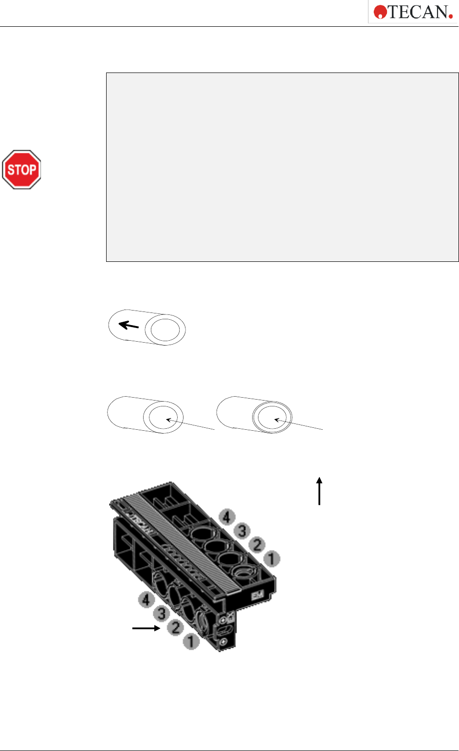
4. Operating the Instrument
64 IFU for Infinite 200 PRO No. 30125944 Rev. No. 1.4 2021-06
Filter Types
CAUTION
THERE ARE TWO TYPES OF FILTERS. IT IS IMPORTANT THAT LIGHT
TRAVELS THROUGH BOTH TYPES OF FILTER IN THE CORRECT
DIRECTION. BEFORE INSERTING A NEW FILTER CAREFULLY
CONSIDER THE FILTER AND THE DIRECTION OF LIGHT THROUGH
THE FILTER SLIDE.
(TRANSLATION FOR GERMAN USERS)
VORSICHT
ES GIBT ZWEI FILTERTYPEN. ACHTEN SIE BEI DER INSTALLATION
DARAUF, DASS DIE FILTER IN DER KORREKTEN ORIENTIERUNG
MONTIERT SIND. BEVOR EIN NEUE FILTERSCHLITTEN VERWENDET
WIRD, PRÜFEN SIE BITTE SORGFÄLTIG, OB DER KORREKTE TYP IN
DER RICHTIGEN ORIENTIERUNG MONTIERT WURDE.
Filters with an arrow on the side:
Light must travel in the direction of the arrow.
Filters without an arrow on the side:
Correct
Incorrect
Direction of light Direction of light
The end of the filter with the metal lip must face away from the light source.
Figure 24: Infinite F configurations: Filter Slide - Direction of Light
Direction
of light
Direction of light
(Excitation)
(Emission)

4. Operating the Instrument
2021-06 IFU for Infinite 200 PRO No. 30125944 Rev. No. 1.4 65
Position of Polarization Filters
Note
Fluorescence polarization measurements on the Infinite F Plex require
two identical excitation and emission filters placed together with the
polarizers either on the positions 1 and 2 or 3 and 4.
(TRANSLATION FOR GERMAN USERS)
Hinweis
Für Fluoreszenz-Polarisations-Messungen mit Infinite F
Konfigurierungen sind zwei identische Excitations- und Emissions-
Filter erforderlich. Die Filter müssen am Filterslide gemeinsam mit den
entsprechenden Polarisationsfolien auf die Positionen 1 und 2 oder 3
und 4 gesetzt werden.
The Infinite F Plex filter slide can be equipped with a maximum of two different
fluorescence polarization filter pairs as each fluorescence polarization
measurement requires two identical excitation and emission filters, which are
placed together with the polarizers either on the position 1 and 2 or 3 and 4.
Figure 25: Infinite F Plex: Filter slide with the indicated positions for fluorescence
polarization filters and polarizers.
4.4.3 Installing a Custom Filter
When installing a new filter use the filter assembly tool included in the
accessories case. For installing the polarizers use the soft tweezers (plastic).
Removing a Filter
Align the filter assembly tool with the notch of the stop-ring. Turn the tool and
remove the stop-ring by pulling it out of the filter slot.
The filter will slide out of the filter slot when the filter carrier is turned over. Do not
use the filter assembly tool to remove filters.
Stop-ring

4. Operating the Instrument
66 IFU for Infinite 200 PRO No. 30125944 Rev. No. 1.4 2021-06
Mounting a Custom Filter
A new filter (and polarizer) must be inserted into the slide as shown below.
Note
Make sure that the filters are inserted correctly (see Filter Types). To
ensure proper function, do not reuse the stop-rings more than 5 times.
(TRANSLATION FOR GERMAN USERS)
Hinweis
Stellen Sie sicher, dass die Filter korrekt installiert sind (siehe
Filtertypen). Die Stopp-Ringe dürfen nicht öfter als 5x verwendet
werden.
CAUTION
TAKE CARE TO INSERT THE POLARIZERS AND THE FILTERS INTO
THE FILTER SLIDE WHEN WORKING WITH FLUORESCENCE
POLARIZATION.
(TRANSLATION FOR GERMAN USERS)
VORSICHT
FÜR FLUORESZENZPOLARISATIONSMESSUNGEN MÜSSEN
POLARISATIONSFOLIEN IMMER ZUSAMMEN MIT DEN FILTERN IN DEN
FILTERSCHLITTEN EINGESETZT WERDEN.
Filter
Filter slide
Stop-ring
Polarizer

4. Operating the Instrument
2021-06 IFU for Infinite 200 PRO No. 30125944 Rev. No. 1.4 67
CAUTION
THE FILTERS ARE PRECISION OPTICAL COMPONENTS, WHICH
SHOULD BE HANDLED BY THE EDGES AND NOT SCRATCHED OR
STORED FACE DOWN IN A DRAWER. ONCE THE FILTERS ARE
INSTALLED IN THE SLIDE, THEY ARE RELATIVELY WELL PROTECTED,
BUT CARE SHOULD BE EXERCISED WHEN HANDLING OR STORING
THEM.
(TRANSLATION FOR GERMAN USERS)
VORSICHT
FILTER SIND PRÄZISE OPTISCHE KOMPONENTEN, DIE NUR AM RAND
BERÜHRT WERDEN DÜRFEN. DIE OBERFLÄCHE DER FILTER IST
EMPFINDLICH GEGENÜBER HARTEN UND RAUHEN OBERFLÄCHEN.
LEGEN SIE DAHER DEN FILTER NIE MIT DER OBERFLÄCHE AUF EINEN
TISCH, DA DER FILTER SONST ZERKRATZT WERDEN KÖNNTE. IM
EINGEBAUTEN ZUSTAND SIND DIE FILTER GUT DURCH DEN
FILTERSCHLITTEN GESCHÜTZT. TROTZDEM SOLL AUCH MIT DEM
FILTERSCHLITTEN SORGFÄLTIG HANTIERT WERDEN UND RICHTIG
GELAGERT WERDEN.
In order to install a custom filter do the following:
If required, carefully insert a polarizer at the excitation and emission half of the
filter slide using tweezers, taking care not to scratch it or get fingerprints on it.
Carefully insert the filter into the opening, taking care not to scratch or get
fingerprints on the filter.
Place the stop-ring on the end of the filter assembly tool and turn it so it cannot
slip off.
Using the filter assembly tool, push the stop-ring into the filter slot and press
firmly into place.
Rotate the tool until the notch in the stop-ring is aligned with the end of the filter
assembly tool and remove the tool.
If there are unused openings remaining after the required filters have been
inserted (e.g. the emission part of an absorbance filter), filter dummies should be
mounted in the holes that are still open.
Filter assembly tool with
stop-ring

4. Operating the Instrument
68 IFU for Infinite 200 PRO No. 30125944 Rev. No. 1.4 2021-06
4.4.4 Defining the Filters
CAUTION
ANY CHANGES TO THE FILTERS IN THE FILTER SLIDE ARE TO BE
CARRIED OUT BY TRAINED PERSONNEL! THE INSTRUMENT IS ABLE TO
RECOGNIZE PREDEFINED FILTER SLIDES AND YOU SHOULD NOT
ATTEMPT TO CHANGE THE FILTER VALUES.
HOWEVER, IF THE FILTERS IN THE FILTER SLIDE HAVE BEEN CHANGED
(BY A SERVICE ENGINEER) OR IF A NEW UNDEFINED CUSTOMIZED
FILTER SLIDE IS TO BE USED, THE FILTER SLIDES NEED TO BE
DEFINED.*
*DEPENDING ON THE FREQUENCY OF USE AND ENVIRONMENTAL
CONDITIONS, OPTICAL FILTERS MAY DETERIORATE OVER TIME AND
THEREFORE HAVE A LIMITED LIFETIME.
(TRANSLATION FOR GERMAN USERS)
VORSICHT
ÄNDERUNGEN AN DEN FILTERN UND FILTERSCHLITTEN DÜRFEN NUR
VON TRAINIERTEN PERSONEN DURCHGEFÜHRT WERDEN. DAS GERÄT
ERKENNT VORDEFINIERTE FILTERSCHLITTEN, DEREN BELEGUNG
NICHT GEÄNDERT WERDEN SOLLTE. FALLS ÄNDERUNGEN
ERFORDERLICH SIND ODER NICHT DEFINIERTE FILTERSCHLITTEN
VERWENDET WERDEN, MÜSSEN DIESE VOR BENUTZUNG SORGFÄLTIG
DEFINIERT WERDEN. **
** IN ABHÄNGIGKEIT DER VERWENDUNGSHÄUFIGKEIT UND DER
UMGEBUNGSBEDINGUNGEN KÖNNEN SICH OPTISCHE FILTER ÜBER DIE
ZEIT VERÄNDERN. SIE HABEN DAHER EINE BEGRENZTE
LEBENSDAUER.
Define a filter (pair) as follows:
Select Filter Definitions from the Settings menu.
The following dialog box is displayed showing an overview tab and four filter
definition tabs:

4. Operating the Instrument
2021-06 IFU for Infinite 200 PRO No. 30125944 Rev. No. 1.4 69
Overview: The overview provides the user with the current filter slide definition.
Filter Slide Description: Enter the filter slide description or the filter slide
description will be generated automatically.
Note
No special characters (blank, ?, $, %, ., /, etc.) except '_' are allowed for
the filter slide description.
(TRANSLATION FOR GERMAN USERS)
Hinweis
Die Filterschlittenbezeichnung darf keine Sonderzeichen außer '_'
beinhalten.
CAUTION
THE FILTER SLIDE DESCRIPTION IS PART OF THE G-FACTOR KEY
VALUE. IF MANUALLY ENTERED, AVOID USING THE SAME
DESCRIPTION FOR THE DIFFERENT FILTER SLIDES.
(TRANSLATION FOR GERMAN USERS)
VORSICHT
G-FAKTOREN WERDEN MIT DER ENTSPRECHENDEN
FILTERSCHLITTENBEZEICHNUNG ABGESPEICHERT. UM EIN
KORREKTES LADEN BEREITS GESPEICHERTER G FAKTOREN ZU
ERMÖGLICHE, DÜRFEN VERSCHIEDENE FILTERSCHLITTEN NICHT MIT
DERSELBEN BEZEICHNUNG VERSEHEN WERDEN.
Position 1 - 4: Filter definition editor for the filters (filter pairs) on positions 1, 2, 3
and 4.
Select the appropriate filter position and enter the new wavelength, bandwidth
and measurement mode for each new filter:
Measurement Mode: chose from the dropdown list ‘FI’ for fluorescence intensity,
ABS for absorbance, ‘FP’ for fluorescence polarization and ‘Empty’ for filter-free
positions

4. Operating the Instrument
70 IFU for Infinite 200 PRO No. 30125944 Rev. No. 1.4 2021-06
Note
Fluorescence polarization mode on Position 1 requires the same filter
settings on Position 2 and vice versa. Fluorescence polarization mode
on Position 3 requires the same filter settings on Position 4 and vice
versa. This is performed automatically.
(TRANSLATION FOR GERMAN USERS)
Hinweis
Fluoreszenzpolarisation als Messmodus auf Position 1 verlangt die
gleichen Filtereinstellungen auf Position 2 und umgekehrt.
Fluoreszenzpolarisation als Messmodus auf Position 3 verlangt die
gleichen Filtereinstellungen auf Position 4 und umgekehrt.
Die zweite Filtereinstellung wird immer automatisch durch die Software
eingestellt.
CAUTION
MAKE SURE THAT THE FILTER SLIDE CONTAINS POLARIZERS
TOGETHER WITH THE FILTERS DEFINED FOR FLUORESCENCE
POLARIZATION.
(TRANSLATION FOR GERMAN USERS)
VORSICHT
VERGEWISSERN SIE SICH, DASS DER FILTERSCHLITTEN DIE
POLARISATIONSFOLIEN ZUSAMMEN MIT DEN FÜR DIE
FLUORESZENZPOLARISATION DEFINIERTEN FILTERN ENTHÄLT.
Wavelength: Enter the filter wavelength within the following range:
(1) Fluorescence intensity mode: 230 to 850 nm (Excitation) and 280 to 850 nm
(Emission)
(2) Fluorescence polarization: 300 to 850 nm (Excitation) and 330 to 850 nm
(Emission)
(3) Absorbance mode: 230 to 1000 nm
Bandwidth: Enter the bandwidth (nm) of the filter
(4) Accept the new filter values by clicking Save. By closing the Filter Definition
dialog the system is ready to collect data with the new filters.
Description: This field can be used for individual user’s remarks about the filter,
e.g. filter name, application, etc.
Note
No special characters (blank, ?, $, %, ., /, etc.) except '_' are allowed for
the filter slide description.
(TRANSLATION FOR GERMAN USERS)
Hinweis
Die Filterschlittenbezeichnung darf keine Sonderzeichen außer '_'
beinhalten.

4. Operating the Instrument
2021-06 IFU for Infinite 200 PRO No. 30125944 Rev. No. 1.4 71
Purchase Date: This option enables the user to enter the purchase or installation
date of the filter
Flash Counter: The flash counter monitors the number of flashes through a filter.
The flash counter number provides the user only with additional information about
the filter in use. The flash counter number is saved together with other
information about the filter on the filter slide microchip.
If you replace a filter, this information will be lost unless the last filter flash number
is manually documented by the user.
For a brand new filter, set the counter to 0. For a previously used filter, enter the
last collected flash number if the number is available.
CAUTION
IT IS RECOMMENDED TO MANUALLY DOCUMENT THE LAST FLASH
COUNTER NUMBER BEFORE REPLACING THE FILTER; OTHERWISE
THIS INFORMATION WILL BE LOST.
(TRANSLATION FOR GERMAN USERS)
VORSICHT
VOR AUSTAUSCH EINES FILTERS WIRD EMPFOHLEN, DIE MIT DER
FUNKTION ‘FLASH COUNTER’ ERFASSTE ZAHL MANUELL ZU
DOKUMENTIEREN. ANDERNFALLS KANN DIE ‚FLASH COUNTER’
INFORMATION VERLOREN GEHEN, DA SIE NICHT AUTOMATISCH
MITGESPEICHERT WIRD.
CAUTION
DO NOT INSERT FILTERS SLIDES IF THE INSTRUMENT IS NOT
SWITCHED ON AND CONNECTED.
(TRANSLATION FOR GERMAN USERS)
VORSICHT
BITTE FÜHREN SIE KEINEN FILTERSCHLITTEN INS GERÄT EIN,
SOLANGE DIESES AUSGESCHALTET ODER NICHT VERBUNDEN IST.

4. Operating the Instrument
72 IFU for Infinite 200 PRO No. 30125944 Rev. No. 1.4 2021-06
4.5 Optimizing Fluorescence Measurements
Fluorescence measurement results may be optimized by tuning instrument
parameters on the one hand, and by selecting appropriate materials on the other
hand.
4.5.1 Instrument Parameters
Gain Settings
The Infinite configurations fluorescence detection system uses an analog to
digital (ADC: Analog Digital Converter) conversion of PMT signal. The gain
setting controls the amplification of the PMT when converting fluorescence light
into electrical current. The ADC needs a suitable input range of PMT current to
provide a proper signal to noise ratio (S/N) on the one hand, and linearity on the
other hand. Therefore, the gain should be tuned to make highest concentration
microplate wells give highest possible readings. Then, readings of lower
concentration microplate wells separate from background - as far as the
background noise level allows for that.
Note
If any well of interest is assigned “OVER” (overflow), you may manually
reduce the gain, or select an automatic gain option (see the software
Instructions for Use).
(TRANSLATION FOR GERMAN USERS)
Hinweis
Wenn einem gemessenen Well ‘Over’ (Überlauf) zugewiesen wird,
können Sie den Verstärkungsgrad des PMT manuell verringern oder
eine automatische Verstärkung in der Software vorwählen (siehe auch
Software-Handbuch).
PMT Properties
The gain for fluorescence intensity is selectable from 1 – 255. The performance
of the PMT depends on the supply voltage. The Infinite reader PMTs are
specified from 300 to 1250 V. The relationship between the gain settings of the
Infinite reader and the voltage supply is described in Equation 1. The intended
use of the Infinite reader PMT is therefore specified for gain settings from 60 to
255. Gain settings below 60 are possible, but the performance of the PMT is not
specified for voltage supply < 300 V. Tecan therefore does not take responsibility
for measurement results of Infinite reader when using gain settings below 60.
Equation 1:
V1250*
255
Gain
U =
Where U is the voltage, Gain is the selected gain setting, 255 is the maximum
possible gain and 1250 V is the maximum voltage supply of the PMT.
Example:
A gain of 100 corresponds to a voltage supply of 490 V:
Equation 2:
V4901250*
255
100
U ==

4. Operating the Instrument
2021-06 IFU for Infinite 200 PRO No. 30125944 Rev. No. 1.4 73
4.5.2 Z-Optimization (FI Top measurements with Infinite M
configurations only)
A useful feature of the Infinite M configurations is the z-optimization procedure.
Z-Optimization is only available for FI Top measurements with the Infinite M
configurations). For a particular assay, this procedure should be performed once
to determine the optimum working distance between the sample in the plate and
the fluorescence optics.
The z-position can be determined as follows:
(1) Manual:
When using the option manual, a numeric z-position value can be entered in
the measurement strip. The default manual z-position is 20000 µm.
(2) Calculated from well:
When using the option calculated from well, the Infinite M configurations
will automatically identify the z-position of maximum signal in the selected
well for further measurements.
(3) Same as for multi-labeling measurements:
When using the option same as, the Infinite M configurations will
automatically use the same z-position as for a previously defined label.
E.g. in a script with 2 FI Top labels named as Label 1 and Label 2 the z-
position of Label 1 can also be used for Label 2 by selecting the option
Same as = Label 1.
(4) Instrument → Z-Position:
When using the Z-position function in the instrument menu, the user can
determine the appropriate z-position from a graphical plot that shows the
well(s) used for z-positioning. The selected value is applied for further
measurements.

4. Operating the Instrument
74 IFU for Infinite 200 PRO No. 30125944 Rev. No. 1.4 2021-06
Select Z-Position from the Instrument menu:
Select the label(s) for which the z-position optimization shall be performed. The
optimal z-position can be simultaneously determined for up to 4 labels.
The label selection/number of labels depends on the measurement script
previously defined in i-control. Additionally, if the z-position of one of the labels is
defined as ‘Same as’, the label will be displayed but it cannot be selected for the
z-optimization:
For each selected label, one or two wells of the defined plate range can be used
for the z-position optimization. Select the well(s) and click ‘Scan’ to start the z-
optimization:

4. Operating the Instrument
2021-06 IFU for Infinite 200 PRO No. 30125944 Rev. No. 1.4 75
The z-positioning option ‘Max S/B Ratio’ requires the measurement of two wells,
one filled with a fluorophore of interest (signal) and one filled with buffer (blank).
Both wells are scanned, and the resulting signal and blank curves are shown in
the graph. The z-position may now be set to the maximum signal-to-blank (S/B)
ratio:

4. Operating the Instrument
76 IFU for Infinite 200 PRO No. 30125944 Rev. No. 1.4 2021-06
Note
When the option ‘Max S/B Ratio’ is used, the sample well is first
measured with optimal gain and the very same gain value is then
applied to the second measurement with the blank well. Therefore, both
signal and blank curves are directly comparable.
(TRANSLATION FOR GERMAN USERS)
Hinweis
Bei Verwendung der Funktion "Maximale Signal/Blank Ratio" wird
zunächst das Signalwell mit "Optimal Gain" gemessen und der
ermittelte Gainwert in der Folge auch für das Blankwell angewendet.
Dadurch sind Blank- und Signalkurve direkt miteinander vergleichbar.
The z-position for each selected label can be defined manually. In the graph
window, the vertical yellow bar can be moved to the desired z-position.
Upon clicking ‘Apply’, the selected z-position will be automatically applied to the
i-control script and used for the subsequent measurement.

4. Operating the Instrument
2021-06 IFU for Infinite 200 PRO No. 30125944 Rev. No. 1.4 77
Flash Settings
On the fly measurements with 1 flash (read) per well are possible for all plate
types; however, measurement precision at low light levels depends on the
reading time while fluorescence signal can be received.
Note
Increase the number of flashes (reads) per well until noise of BLANK
wells does not further improve, or until measurement time per well
becomes unacceptable.
(TRANSLATION FOR GERMAN USERS)
Hinweis
Erhöhen Sie die Zahl der Blitze (No. of reads) pro Kavität, bis sich das
Rauschen der UNBELEGTEN Kavitäten nicht weiter verringert oder bis
die Messzeit pro Kavität noch gerade annehmbar ist.
For prompt fluorescence it does not help to increase the default integration time,
because the detector will not receive more signal once the flash has vanished.
Timing Parameters for Time Resolved Fluorescence
For TRF, signal integration parameters need to be adjusted according to the
label. The start of the signal Integration Time is delayed against the preceding
flash by a Lag Time. TRF timing parameters may be established with the
following procedure:
As a starting point you may take the Fluorescence Lifetime of the label for both
Integration Time and Lag Time.
Coarse tuning: With Integration Time being fixed reduces the Lag Time to
maximize Signal to Background (S/B).
Fine tuning: With Lag Time being fixed extends the Integration Time and check, if
S/B further improves.
Optional Fine-tuning: With either timing parameter being fixed you may vary the
other one and check, if S/B further improves.
Settle Time
Before measuring a well, a settle time may be set. Due to the stop and go motion
of the plate carrier the meniscus of the dispensed liquid may still vibrate while
signal is integrated. This can give rise to fluctuations of the measured values. The
effect has been observed in wells of 96-well plates and larger wells. In particular,
it is critical with absorbance measurements.

4. Operating the Instrument
78 IFU for Infinite 200 PRO No. 30125944 Rev. No. 1.4 2021-06
4.5.3 FI Ratio Mode
Ratio Mode
Up to 4 labels may be measured well-wise. This measurement mode is called
‘ratio mode’. Be aware that no ‘ratio’ calculation is performed after this
measurement. The Excel result sheet shows the raw data. Further calculations
have to be performed by the user.
Filter Switch Time (Infinite F configurations)/Wavelength Switch Time (Infinite M
configurations)
The Infinite F configurations can switch between two filters within 250 ms in case
that the selected labels are measured with the same gain. Otherwise, the
switching time is 400 ms. In this case the high voltage level at the PMT needs to
be changed. The high voltage applied to the PMT needs some time to stabilize.
The Infinite M configurations can switch between two wavelengths within 150 ms
in case that the selected labels are measured with the same gain and no order
sorting (OS) switching point is involved (see Table 1:for switching points).
Otherwise, the switching time is 400 ms. In this case the high voltage level at the
PMT needs to be changed. The high voltage applied to the PMT needs some
time to stabilize. The OS filter wheel needs to be moved.
Excitation
Wavelength
Emission
Wavelength
OSF Switching Point 1
316 nm
401 nm
OSF Switching Point 2
386 nm
621 nm
OSF Switching Point 3
561 nm
-
Table 1: OSF (Order Sorting Filter) Switching Points (Infinite M configurations)
Example:
Fura-2: This application involves a filter/wavelength switch between 340 and
380 nm on the excitation side. The emission is measured at about 510 nm. The
excitation filter/wavelength switch does not include an OS switch, therefore the
switch is possible within 150 ms on an Infinite M configurations and 250 ms on an
Infinite F configurations.

4. Operating the Instrument
2021-06 IFU for Infinite 200 PRO No. 30125944 Rev. No. 1.4 79
4.6 FP Measurements
4.6.1 Fluorescence Polarization
Fluorescence Polarization (FP, P) is defined by the following equation:
Equation 3:
where I
and I
⊥
equal the emission intensity of the polarized light parallel and
perpendicular to the plane of excitation, respectively. Polarization is a
dimensionless unit, generally expressed in mP units.
To start an FP measurement, the program strip must contain a valid
measurement Blank range and valid G-Factor settings.
4.6.2 Measurement Blank Range
Measurement blank reduction is performed automatically at each fluorescence
polarization measurement; the mean value of the respective blank wells will be
subtracted from each sample value (see 4.6.8).
In the Measurement group box, select the Blank range by clicking Change and
then selecting the wells filled with the measurement (sample) blank.
( )
( )
⊥
⊥
+
−
=
II
II
P
||
||

4. Operating the Instrument
80 IFU for Infinite 200 PRO No. 30125944 Rev. No. 1.4 2021-06
4.6.3 G-Factor Settings
The given equation for calculation of fluorescence polarization assumes that the
sensitivity of the detection system is equivalent for parallel and perpendicular
polarized light. This is generally not the case and either the parallel or
perpendicular intensity must be corrected by so called ‘G-Factor’. The G-factor
compensates for differences in optical components between parallel and
perpendicular measurement.
The G-Factor is the correction factor that can be determined for the wavelength of
the fluorophore by measuring a sample with a known polarization value. A valid
calibration of the instrument resulting in a G-factor is an important requirement for
each fluorescence polarization measurement.
CAUTION
MAKE SURE THAT THE FILTER SLIDE CONTAINS POLARIZERS
TOGETHER WITH THE FILTERS DEFINED FOR FLUORESCENCE
POLARIZATION. MEASUREMENTS WITHOUT THE POLARIZERES WILL
RESULT IN A FALSE G-FACTOR AND FALSE MEASUREMENT DATA.
(TRANSLATION FOR GERMAN USERS)
VORSICHT
VERGEWISSERN SIE SICH, DASS DER FILTERSCHLITTEN DIE
POLARISATIONSFOLIEN ZUSAMMEN MIT DEN FÜR DIE
FLUORESZENZPOLARISATION DEFINIERTEN FILTERN ENTHÄLT.
MESSUNGEN OHNE POLARIZATIONSFOLIEN WERDEN EINEN
FALSCHEN G-FAKTOR UND FALSCHE MESSDATEN LIEFERN.
4.6.4 Measurement with an Uncalibrated G-Factor
If no calibrated G-factor is available, the default value of 1 will be displayed and
marked as ‘Uncalibrated G-Factor’. In order to enable the measurement, confirm
this value or select a new one by either clicking the up and down arrows or
entering a value in the G-Factor field.
For the G-Factor calibration, see 4.6.5.

4. Operating the Instrument
2021-06 IFU for Infinite 200 PRO No. 30125944 Rev. No. 1.4 81
4.6.5 Measurement with a Simultaneous G-Factor Calibration
When Calibrate is selected, the G-factor is determined for the current
measurement parameters and used for the following FP measurement. In order
to perform the G-Factor calibration, please define:
Reference value: select a polarization value for the reference used, e.g. 20 mP
for a 1 nM Fluorescein solution in 0.01 M NaOH.
Reference range: click Change and select the wells filled with the reference.
Blank range: click Change and select the wells filled with the reference blank.
Select Same as measurement blank if the reference blank is the same as the
measurement blank.
Note
By filling in more than one well with polarization references and
reference blanks, the mean values will be calculated and therefore the
calibration result will be more accurate.
(TRANSLATION FOR GERMAN USERS)
Hinweis
Bei Verwendung von mehr als einem ‚Well’ für die Positionen
‚Polarization Reference’ und ‚Polarization Blank’, werden für die
Kalibration und für die weiteren Berechnungen die Mittelwerte
herangezogen. Die Kalibration wird duch Mehrfachbestimmung
genauer.

4. Operating the Instrument
82 IFU for Infinite 200 PRO No. 30125944 Rev. No. 1.4 2021-06
G-Factor Storage
The calculated G-Factor is automatically stored on the computer’s hard drive.
Each G-Factor entry corresponds to the filter pair selection as well as the filter
slide description. There is always only one G-Factor available for the respective
filter pair combination and filter slide description, unless the same filter pair has
been used with the different filter slides and thus stored with the different filter
slide descriptions.
CAUTION
THE FILTER SLIDE DESCRIPTION IS PART OF THE G-FACTOR KEY
VALUE. AVOID USING THE SAME FILTER SLIDE DESCRIPTION FOR
DIFFERENT FILTER SLIDES AS THIS WILL AFFECT THE CORRECT G-
FACTOR RECOGNITION.
(TRANSLATION FOR GERMAN USERS)
VORSICHT
G-FAKTOREN WERDEN MIT DER ENTSPRECHENDEN
FILTERSCHLITTENBEZEICHNUNG ABGESPEICHERT. UM EIN
KORREKTES LADEN BEREITS GESPEICHERTER G-FAKTOREN ZU
ERMÖGLICHE, DÜRFEN VERSCHIEDENE FILTERSCHLITTEN NICHT MIT
DERSELBEN BEZEICHNUNG VERSEHEN WERDEN.
4.6.6 Measurement with a Calibrated G-Factor
Note
Once calibrated, the G-factor is shown and can be used immediately if
it matches the Ex/Em wavelength pair and the filter slide description.
(TRANSLATION FOR GERMAN USERS)
Hinweis
Kalibrierte G-Faktoren werden in der Software abgespeichert. Sie
werden automatisch angezeigt wenn die vom User gewählten
Excitations- und Emissionswellenlängen sowie die
Filterschlittenbezeichnung mit den Daten des abgespeicherten
G-Faktors übereinstimmen.
A calibrated G-factor will be displayed automatically or can be loaded by clicking
the '>>' button only if it matches the selected fluorescence polarization filter pair
and the filter slide description.

4. Operating the Instrument
2021-06 IFU for Infinite 200 PRO No. 30125944 Rev. No. 1.4 83
The calibrated G-Factor is marked as ‘Calibrated G-Factor’ with date and
signature.
4.6.7 Measurement with a Manual G-Factor
If the displayed G-Factor does not match the calibrated value (e.g. the G-Factor
has been manually changed or loaded with a method), the corresponding value
will be marked as ‘Manual G-Factor’.
The calibrated G-Factor can be restored by clicking the ‘>>’ button on the left side
of the displayed G-Factor.
Note
G-Factor adjustment via '>>' button is only possible, if a calibrated
G-Factor is available for the corresponding wavelength.
(TRANSLATION FOR GERMAN USERS)
Hinweis
Das Laden eines gespeicherten G-Faktors mit '>>' Knopf ist nur dann
möglich, wenn es einen kalibrierten Wert für die verwendete
Wellenlänge gibt.

4. Operating the Instrument
84 IFU for Infinite 200 PRO No. 30125944 Rev. No. 1.4 2021-06
4.6.8 Calculation of Fluorescence Polarization Parameters
G-Factor:
))(1(
))(1(
par
buf
par
ref
ref
cross
buf
cross
ref
ref
RFURFUP
RFURFUP
G
−−
−+
=
bufferofunitscefluorescenrelativeAveragedRFU
referenceofuni tscefluorescenrelativeAveragedRFU
referenceofvalueonPola rizatiP
buf
ref
ref
...
...
P ...
Blank Reduction:
The mean value of the respective blank wells is subtracted from each value.
welleachfor
RFURFU
RFURFU
RFURFU
RFURFU
RFU
par
blk
par
blk
par
blk
par
smp
par
buf
par
buf
par
buf
par
ref
par
−
−
−
−
=
welleachfor
RFURFU
RFURFU
RFURFU
RFURFU
RFU
cross
blk
cross
blk
cross
blk
cross
smp
cross
buf
cross
buf
cross
buf
cross
ref
cross
−
−
−
−
=
Intensities:
Parallel and perpendicular intensities are calculated using the following formulas:
parpar
RFUGI = *
crosscross
RFUI =
Polarization:
crosspar
crosspar
II
II
P
+
−
=
Anisotropy:
crosspar
crosspar
II
II
A
*2+
−
=
Total Intensity:
crosspar
tot
III *2+=

4. Operating the Instrument
2021-06 IFU for Infinite 200 PRO No. 30125944 Rev. No. 1.4 85
4.7 Optimizing Absorbance Measurements
4.7.1 Measurement Parameters
Flash Settings
On the fly measurements with 1 flash (read) per well are possible for all plate
types; however, measurement precision at low light levels depends on the
reading time during which a fluorescence signal can be received.
Note
Increase the number of flashes (reads) per well until noise of BLANK
wells does not further improve, or until measurement time per well
becomes unacceptable.
(TRANSLATION FOR GERMAN USERS)
Hinweis
Erhöhen Sie die Zahl der Blitze (No. of reads) pro Kavität, bis sich das
Rauschen der UNBELEGTEN Kavitäten nicht weiter verringert oder bis
die Messzeit pro Kavität noch gerade annehmbar ist.
Settle Time
A settle time before measuring a well may be set (critical for absorbance
measurements). Due to the stop and go motion of the plate carrier the meniscus
of the dispensed liquid may still vibrate while signal is integrated. This can give
rise to fluctuations of the measured values. The effect has been observed in wells
of 96-well plates and larger wells.
4.7.2 Absorbance Ratio Mode
Ratio Mode
Using the “Standard”-tab in i-control up to 4 labels may be measured well-wise.
This measurement mode is called ‘ratio mode’. Be aware that no ‘ratio’
calculation is performed after this measurement. The Excel result sheet shows
the raw data. Further calculations have to be performed by the user.
Using the “Applications”-tab in i-control together with the NanoQuant Plate, the
raw data for “Quantifying Nucleic Acids” and “Labeling Efficiency” are all
automatically calculated for concentration or ratio-calculation by Excel software.
The values can be used for further calculation if preferred.
Wavelength (Infinite M configurations)/Filter (Infinite F configurations) Switch
Time
The Infinite F configurations can switch between two neighboring filters within
250 ms.
The Infinite M configurations can switch between two wavelengths in 150 ms.
For conditions, see 4.5.3 FI Ratio Mode.

4. Operating the Instrument
86 IFU for Infinite 200 PRO No. 30125944 Rev. No. 1.4 2021-06
4.8 Multiple Reads per Well
The i-control software allows Multiple Reads per Well (MRW) to be performed in
absorbance, fluorescence top and fluorescence bottom mode.
The Multiple Reads per Well functions can be activated on an absorbance or
fluorescence intensity program strip by selecting the ‘Multiple Reads per Well’
check box (see Figure 26 below).
Figure 26: Multiple Reads per Well
Note
The function ‘Multiple Reads per Well’ is only available for the fixed
wavelength reading modes ‘absorbance’, ‘fluorescence intensity top’
and ‘fluorescence intensity bottom’. The function is not available for
scan measurements.
(TRANSLATION FOR GERMAN USERS)
Hinweis
Die Funktion ‚Multiple Reads per Well’ ist nur für die Messmodi
‚Absorbance’; Fluorescence Intensity Top’ und ‚Fluorescence Intensity
Bottom’ verfügbar. Diese Funktion steht nicht für Scan-Messungen zur
Verfügung.
4.8.1 MRW Type
The MRW types define the pattern how the measurement will be performed. The
software allows seven different MRW types to be selected:
• Square
• Square (filled)
• Circle
• Circle (filled)
• X-line
• Y-line
• XY-line

4. Operating the Instrument
2021-06 IFU for Infinite 200 PRO No. 30125944 Rev. No. 1.4 87
Pattern examples:
Square:
Square (filled):
Circle:
Circle (filled):
X-line:
Y-line:
XY-line:
4.8.2 MRW Size
The MRW size determines the number of points to be measured in a well.
Depending on the microplate type and instrument, Infinite F configurations or
Infinite M configurations, the ‘size’ is selectable from 1 x 1 to a maximum of 15 x
15 points. The diameter of the single measurement points corresponds to the
theoretically calculated diameter of the light beam at the focal point (see
Table 2).
Measurement Mode
Infinite M configurations
Infinite F configurations
Fluorescence Intensity Top
3 mm
2 mm
Fluorescence Intensity Bottom
2 mm
2 mm
Absorbance (microplate optics)
0.7 mm
0.5 mm
Table 2: Theoretically calculated beam diameter at the focal point.
The MRW type displayed in the software is therefore only a schematic overview
of the measurement pattern. When measuring real samples the pattern can vary
and the overlap of the single measurement points can be slightly different from
the displayed pattern. It is therefore recommended to optimize the Multiple Reads
per Well parameters for every new application.

4. Operating the Instrument
88 IFU for Infinite 200 PRO No. 30125944 Rev. No. 1.4 2021-06
4.8.3 MRW Border
In addition to ‘Size’ and ‘Type’, a ‘Border’ function allows the user to select a
certain distance between light beam and the wall of the microplate well
(distance in µm). As already stated in chapter 4.8.2, the software displays only a
schematic overview of the measurement pattern. The border is calculated from
the theoretical beam diameter of the instrument. However, when measuring liquid
samples, the light beam diameter is influenced by the type and amount of liquid in
a well.
In addition, the plate type (e.g. material of bottom of the microplate) also
influences the characteristics of the light beam. Therefore the theoretical border
displayed in the software might not correspond to the actual border when
measuring a real sample. It is therefore strongly recommended to optimize the
Multiple Reads per Well parameters for every new application. Make sure that the
selected border ensures sufficient distance between light beam and wall of the
microplate well.
CAUTION
ALL ABSORBANCE AND FLUORESCENCE INTENSITY
SPECIFICATIONS GIVEN IN THIS DOCUMENT ARE ONLY VALID FOR
SINGLE POINT MEASUREMENTS (ONE MEASUREMENT POINT PER
WELL). WHEN USING THE MULTIPLE READS PER WELL OPTION THE
SPECIFICATIONS ARE NOT VALID.
(TRANSLATION FOR GERMAN USERS)
VORSICHT
DIE GERÄTESPEZIFIKATIONEN FÜR ABSORBANCE UND
FLUORESCENCE INTENSITÄT GELTEN NUR FÜR MESSUNGEN MIT
EINEM MESSPUNKT PRO WELL. DIE SPEZIFIKATIONEN SIND NICHT
GÜLTIG FÜR DEN MESSMODUS ‚MULTIPLE READS PER WELL’.
CAUTION
THE SOFTWARE DISPLAYS ONLY A SCHEMATIC VIEW OF THE
MEASUREMENT PATTERN. THEREFORE, OPTIMIZE THE MULTIPLE
READS PER WELL PARAMETERS FOR EVERY NEW APPLICATION.
MAKE SURE THAT THE SELECTED BORDER
IS SUFFICIENT TO AVOID AN OVERLAP BETWEEN THE LIGHT BEAM
AND THE WELL WALL OF THE MICROPLATE.
(TRANSLATION FOR GERMAN USERS)
VORSICHT
DAS IN DER SOFTWARE ANGEZEIGTE MESSMUSTER ENTSPRICHT
NUR EINER SCHEMATISCHEN DARSTELLUNG. FÜR JEDE NEUE
APPLIKATION IST ES DAHER ERFORDERLICH, DIE ‚MULTIPLE READS
PER WELL’ PARAMETER ZU OPTIMIEREN. STELLEN SIE SICHER,
DASS DER GEWÄHLTE ‚BORDER’-WERT AUSREICHT, EINE
ÜBERLAPPUNG DES LICHTSTRAHLS MIT DER MIKROPLATTENWAND
ZU VERHINDERN.

4. Operating the Instrument
2021-06 IFU for Infinite 200 PRO No. 30125944 Rev. No. 1.4 89
CAUTION
A ‘BORDER’ VALUE THAT IS TOO SMALL MAY CAUSE WRONG
MEASUREMENT RESULTS DUE TO OVERLAP BETWEEN THE LIGHT
BEAM AND THE WELL WALL OF THE MICROPLATE.
(TRANSLATION FOR GERMAN USERS)
VORSICHT
WIRD EIN ZU GERINGER ‚BORDER’-WERT FÜR EINE MESSUNG
AUSGEWÄHLT, KANN DAS ZU FALSCHEN MESSERGEBNISSEN
FÜHREN. DIE ÜBERLAPPUNG DES LICHTSTRAHLS MIT DER
MIKROPLATTENWAND KANN DIE MESSERGEBNISSE
BEEINFLUSSEN.
4.8.4 Result Display in MS Excel
The MS Excel
result sheet generated by the i-control software displays a
schematic graphical overview (‘Multiple Reads per Well – Alignment’; see Figure
28) of the measurement points. A number is assigned to each measurement
point. The results are presented in list form: number of measurement point versus
result value (OD or RFU; see Figure 27: Alignment graphic (XY-Line, 3 x 3) for
result of a fluorescence measurement). In addition, the standard deviation
(‘Stdev’) and the average value (‘Mean’) of the measurements points/well are
also displayed:
Figure 27: Alignment graphic (XY-Line, 3 x 3)
Figure 28: Example of MS Excel result list generated by i-control.

4. Operating the Instrument
90 IFU for Infinite 200 PRO No. 30125944 Rev. No. 1.4 2021-06
4.8.5 Miscellaneous Software Features of MRW
MRW is only available for the measurement modes ‘Absorbance’, ‘Fluorescence
Intensity Top’ and ‘Fluorescence Intensity Bottom’.
The MRW feature is not active when performing well-wise measurements.
‘Reference Wavelength’ (located on the absorbance strip) is not available in
combination with ‘Multiple Reads per Well’.

4. Operating the Instrument
2021-06 IFU for Infinite 200 PRO No. 30125944 Rev. No. 1.4 91
4.9 Optimizing Luminescence Measurements
CAUTION
SWITCH ON THE INSTRUMENT AT LEAST 15 MINUTES BEFORE STARTING
A LUMINESCENCE MEASUREMENT. SOME COMPONENTS NEED TO WARM
UP TO GUARANTEE STABLE CONDITIONS FOR THE MEASUREMENT.
(TRANSLATION FOR GERMAN USERS)
VORSICHT
SCHALTEN SIE DAS GERÄT MINDESTENS 15 MINUTEN VOR START EINER
LUMINESZENZ-MESSUNG EIN. EINIGE GERÄTEKOMPONENTEN
BENÖTIGEN EINE AUFWÄRMZEIT, SONST KANN EINE STABILE
LUMINESZENZ-MESSUNG NICHT GARANTIERT WERDEN.
4.9.1 Integration Time
At very low light levels, a PMT does not yield a continuous output current, which
is necessary for a reliable analog to digital conversion. Instead, it produces a
sequence of pulses the average rate of which can be measured using a counter.
The advantage of the photon counting technique at such low light levels is that
pulse height selection criteria allow electronic noise to be discriminated.
At very low light levels the measured counts per second are proportional to the
light intensity. Increase of measurement time per well yields more accurate
values because of the irregular photon impact (photon statistics). The photonic
noise (shot noise) cannot be reduced technically.
Note
The signal to noise (S/N) ratio can be optimized by increasing the
integration time. Increasing the integration time by a factor of 10 results in
an improvement of the S/N ratio by app. a factor of 3.
(TRANSLATION FOR GERMAN USERS)
Hinweis
Das Verhältnis zwischen Signal und Hintergrundrauschen (S/N) kann
optimiert werden, indem man die die Integrationszeit verlängert. Durch eine
Verlängerung der Integrationszeit um den Faktor 10 erzielt man eine
Verbesserung des S/N Verhältnisses um etwa einen Faktor 3.
4.9.2 Light Level Attenuation
When using photon counting detection, optical attenuation of higher
luminescence light levels (>10,000,000 counts per second) is necessary. In such
a case, too many photons enter the luminescence detector at one time and
cannot be distinguished as distinct exit pulses. Count rates would even fall behind
values at lower light levels.
Therefore, values >10,000,000 counts per second (without attenuation) are
displayed as “INVALID” in the results sheet.
The optical luminescence system of the Infinite reader can attenuate light levels
by a fixed factor of either 1 (none) or 100 (2 OD). Correspondingly, the usable
measurement range will be shifted to higher light levels (<1,000,000,000 counts
per second).

4. Operating the Instrument
92 IFU for Infinite 200 PRO No. 30125944 Rev. No. 1.4 2021-06
4.10 Measurements with Injectors
4.10.1 Priming and Washing of the Infinite Reader
CAUTION
THE INJECTOR CARRIER MUST BE IN THE SERVICE POSITION FOR
WASHING UND PRIMING.
PRIME AND WASH MUST NOT BE PERFORMED WHEN THE INJECTOR
IS IN THE INSTRUMENT!
(TRANSLATION FOR GERMAN USERS)
VORSICHT
DIE FUNKTIONEN ‘PRIME’ UND ‘WASH’ DÜRFEN NUR DURCHGEFÜHRT
WERDEN, WENN SICH DER INJEKTOR IN DER SERVICE-POSITION IN
DER INJEKTOR-BOX BEFINDET.
„PRIME“ UND „WASH“ SIND NICHT ERLAUBT, WENN SICH DER
INJEKTOR IM GERÄT BEFINDET.
The initial filling step of the injector system (priming) as well as the cleaning step
of the injector system (washing) must take place outside of the instrument.
For these procedures, the injector carrier is removed from instrument and put into
the service position of the injector box.
Figure 29: Injector-box with injector in ‘service position’; the injectors are removed from the
carrier slot and inserted into the holder of the injector carrier system.
For priming and washing steps of the injector system, a default setting for
injection speed and volume dispensed is provided. If required the priming
parameters can be adjusted in the injector control window of the i-control
software.
The prime volume depends on the tubing length. Two types of injector tubing are
available: ‘long’: 105 cm, and ‘short’: 80 cm.
The minimal priming volume is 700 µl for an injector with short tubing and 850 µl
for an injector with long tubing.
Prime/Wash buttons
for injectors A and B

4. Operating the Instrument
2021-06 IFU for Infinite 200 PRO No. 30125944 Rev. No. 1.4 93
CAUTION
DO NOT TOUCH THE INJECTOR NEEDLES. THEY CAN BECOME EASILY
BENT OR MISALIGNED, WHICH CAN CAUSE INJECTION PROBLEMS OR
DAMAGE THE INSTRUMENT.
IF THE INJECTOR CARRIER IS NOT INSERTED CORRECTLY IN THE
INJECTOR PORT, THE INJECTOR SENSOR DOES NOT DETECT THE
INSERTED INJECTOR AND THEREFORE WASHING AND PRIMING IS
ENABLED WHICH CAN DAMAGE THE INSTRUMENT. IN ADDITION TO
THIS, THE ACTIONS ‘DISPENSE’ AND ‘INJECT’ WILL NOT BE POSSIBLE.
(TRANSLATION FOR GERMAN USERS)
VORSICHT
BITTE BERÜHREN SIE DIE INJEKTORNADELN NICHT. SIE KÖNNEN
LEICHT VERBOGEN ODER VERSCHOBEN WERDEN, WAS ZU
PROBLEMEN BEI DER INJEKTION UND SCHADEN AM GERÄT FÜHREN
KANN.
WENN DER INJEKTOR NICHT VOLLSTÄNDIG IN DIE INJEKTOR-
EINFÜHRUNG EINRASTET, ARBEITET DER INJEKTOR-SENSOR NICHT
KORREKT. TROTZ EINGEFÜHRTEM INJEKTOR IST DANN „PRIME” UND
„WASH” MÖGLICH, WAS ZU ERHEBLICHEN BESCHÄDIGUNGEN IM
GERÄT FÜHREN KANN.
Priming
Before the injection system can be used, an initial filling step (priming) is needed
to remove all air and to completely fill the system with liquid.
It is recommended to perform a washing step before priming.
Priming can be performed by using the i-control software or by using the
hardware buttons on the injector box:
1. Fill the storage bottles with the necessary reagents and insert the feeding
tube(s). Make sure, that the tube(s) reaches the bottom of the bottle.
2. Remove the injector from the carrier slot and insert it into the service position
of the injector box.
3. Put an empty container under the injector.
Priming Procedure (i-control):
1. Adjust parameters on the Prime tab of the Injector Maintenance dialog box in
the Settings menu.
2. Start the priming procedure by clicking Start prime in the Injector
Maintenance dialog box.
3. Visually inspect the syringes for air bubbles. Any bubbles should be removed
after priming to ensure good injection performance.

4. Operating the Instrument
94 IFU for Infinite 200 PRO No. 30125944 Rev. No. 1.4 2021-06
4. Select one of the injectors Injector A or Injector B or Injector A and B.
5. Select the Prime Volume (700 -60000 µl – short tube)
(850 -60000 µl – long tube)
6. Select the Prime Speed (100 - 300 µl/sec).
7. Select the Refill Speed (100 – 300 µl/sec.) or select Refill Speed equal to
Prime Speed.
8. Start prime by clicking the Start prime button.
9. Click the Save as default button to save the selected settings to the
corresponding hardware button (A or B) on the injector box. When using the
hardware buttons for priming, these settings will be applied.
10. Select Close to exit the dialog box
Priming Procedure (Hardware Button):
Priming can also be performed without using the software. Priming parameters
can be stored on the injector by clicking Save as Default on the Prime tab of the
Injector Maintenance dialog box of the i-control software (in the Settings menu,
click Injectors... and the Injector Maintenance dialog box appears). Press the
Prime/Wash button on the injector box to start the priming sequence using the
default parameters, (see Figure 29: Injector-box with injector in ‘service position’,
page 92). The injector must be connected to the instrument and the instrument
must be switched on. Start the prime procedure by pressing the Prime/Wash
button for less than 3 seconds.
Visually inspect the syringes for air bubbles. Any bubbles should be removed
after priming to ensure good injection performance.
After a successful priming procedure, reinsert the injector into the instrument.
Close the lid of the pump module completely before starting a measurement. The
injectors are now ready to use.
When starting a measurement with the actions ‘injection’ or ‘dispense’, 5 µl of
liquid are dispensed into a disposable container on the plate carrier before
starting ‘injection’ or ‘dispense’. This initial dispense step makes sure that the
injection/dispense conditions are equal for each well.

4. Operating the Instrument
2021-06 IFU for Infinite 200 PRO No. 30125944 Rev. No. 1.4 95
CAUTION
CLOSE THE LID OF THE PUMP MODULE (INJECTOR BOX)
COMPLETELY BEFORE STARTING A MEASUREMENT.
(TRANSLATION FOR GERMAN USERS)
VORSICHT
EINE MESSUNG DARF NUR MIT VERSCHLOSSENER INJEKTOR-BOX
GESTARTET WERDEN.
Reagent Backflush
The dead volume of the injection system (injector needles, syringes, valves and
tubing) is approximately 100 µl for each syringe after the backflush procedure has
been performed. The function of backflush is to return any unused reagent to the
reservoir bottles.
The injection speed can be adjusted via the software to allow for good mixing of
reagents. The optimal injection speed depends on the assay parameters, such as
viscosity of fluids, the plate format and the measuring behavior of the liquids.
Reagent backflush allows reagents in the tubing system to be pumped back into
storage bottles. This action can be performed optionally prior to washing the
injector system to minimize the dead volume.
Before performing the Backflush procedure:
Remove the injector carrier from the instrument and insert the injector carrier into
the service position of the injector box.
Insert the feeding tubing into the appropriate storage bottle.
Backflush Procedure (i-control):
Adjust parameters on the Backflush tab of the Injector Maintenance dialog box
in the Settings menu.
Start the reagent backflush procedure by clicking Start backflush.

4. Operating the Instrument
96 IFU for Infinite 200 PRO No. 30125944 Rev. No. 1.4 2021-06
1. Select one of the injectors Injector A or Injector B or Injector A and B (only
‘primed’ injectors are available for ‘backflush’).
2. Select the Piston Strokes (1 – 60; 1 stroke equals 1 ml)
3. Select the Backflush Speed (100 - 300 µl/sec).
4. Select the Refill Speed (100 – 300 µl/sec.) or select Refill Speed equal to
Backflush Speed.
5. Click Start backflush to start the reagent backflush procedure.
6. Click Close to exit the dialog box.
CAUTION
THE INJECTOR CARRIER MUST BE IN THE SERVICE POSITION FOR
THE ACTION ‘BACKFLUSH’.
DO NOT PERFORM BACKFLUSH WHEN THE INJECTOR IS IN THE
INSTRUMENT!
(TRANSLATION FOR GERMAN USERS)
VORSICHT
DIE FUNKTION ‚BACKFLUSH’ DARF NUR DURCHGEFÜHRT WERDEN,
WENN SICH DER INJEKTOR IN DER SERVICE-POSITION IN DER
INJEKTOR-BOX BEFINDET.
’BACKFLUSH’ IST NICHT ERLAUBT, WENN SICH DER INJEKTOR IM
GERÄT BEFINDET.
4.10.2 Washing
Before the instrument is switched off, it is recommended to perform a wash
procedure to clean the injector system.
Washing can be performed by using the i-control software or by using the
hardware buttons on the injector box.
Before performing the washing procedure:
1. Fill the storage bottles with the appropriate wash reagents (distilled water,
70 % ethanol, etc…) and insert the feeding tubes. Make sure, that the tubes
reach the bottom of the bottle.
2. Remove the injector from the carrier slot and insert it into the service position
of the injector box.
3. Put an empty container under the injector.
Washing Procedure (i-control):
Adjust the parameters on the Wash tab of the Injector Maintenance dialog box
in the Settings menu.

4. Operating the Instrument
2021-06 IFU for Infinite 200 PRO No. 30125944 Rev. No. 1.4 97
1. Start the washing procedure by clicking the Start wash.
2. Select one of the injectors Injector A or Injector B or Injector A and B.
3. Select the Piston Strokes (1 – 60; 1 stroke equals 1 ml)
4. Select the Wash Speed (100 - 300 µl/sec).
5. Select the Refill Speed (100 – 300 µl/sec.) or select Refill Speed equal to Wash Speed.
5. Click Start wash to start the wash procedure.
6. Click Close to exit the dialog box.
Washing Procedure (Hardware Buttons):
Washing can also be performed without using the software. Washing parameters
can be stored on the injector by clicking Save as Default on the Wash tab of the
Injector Maintenance dialog box (in the Settings menu, click Injectors... and
the Injector Maintenance dialog box appears) of the i-control software. Press the
Prime/Wash button on the injector box to start the washing sequence using the
default parameters. (see Figure 29: Injector-box with injector in ‘service position’,
page 92). The injector must be connected to the instrument and the instrument
must be switched on. Start the wash procedure by pressing and holding the
Prime/Wash button for more than 3 seconds.

4. Operating the Instrument
98 IFU for Infinite 200 PRO No. 30125944 Rev. No. 1.4 2021-06
CAUTION
THE INJECTOR CARRIER MUST BE IN THE SERVICE POSITION FOR THE
ACTION ‘WASH’.
DO NOT PERFORM WASHING WHEN THE INJECTOR IS IN THE
INSTRUMENT!
(TRANSLATION FOR GERMAN USERS)
VORSICHT
DIE FUNKTION ‚WASH’ DARF NUR DURCHGEFÜHRT WERDEN, WENN
SICH DER INJEKTOR IN DER SERVICE-POSITION IN DER INJEKTOR-BOX
BEFINDET.
’WASH’ IST NICHT ERLAUBT, WENN SICH DER INJEKTOR IM GERÄT
BEFINDET.
IMPORTANT
BE SURE TO RUN A FINAL WASH PROCEDURE WITH DISTILLED WATER
AND EMPTY THE INJECTOR SYSTEM. FOR GOOD CARE AND LIFETIME
FILL THE INJECTOR SYSTEM WITH LIQUID (WATER) BEFORE TURNING
OFF THE INSTRUMENT.
(TRANSLATION FOR GERMAN USERS)
WICHTIG
DER LETZTE WASCH-SCHRITT MUSS IMMER MIT DESTILLIERTEM
WASSER DURCHGEFÜHRT WERDEN UND DAS INJEKTORSYSTEM
KOMPLETT ENTLEERT WERDEN. FÜR OPTIMALE PFLEGE UND LANGE
LEBENSDAUER IST DAS INJEKTORSYSTEM ANSCHLIEßEND MIT
DESTILLIERTEM WASSER ZU FÜLLEN.
IMPORTANT
PLEASE SEE THE CORRESPONDING REAGENT KIT FOR ADVICE ON
HOW TO REMOVE THE SUBSTRATE COMPLETELY FROM THE TUBING
SYSTEM.
(TRANSLATION FOR GERMAN USERS)
WICHTIG
DIE KORREKTE ANLEITUNG ZUR ENTFERNUNG ALLER
SUBSTRATRÜCKSTÄNDE AUS DEM INJEKTORSYSTEM ENTNEHMEN
SIE BITTE DER JEWEILIGEN KIT-BESCHREIBUNG.
4. Operating the Instrument
2021-06 IFU for Infinite 200 PRO No. 30125944 Rev. No. 1.4 99
IMPORTANT
TAKE GOOD CARE OF THE INJECTORS, BECAUSE IF THEY ARE
DAMAGED THE ACCURACY OF DISPENSING MAY BE AFFECTED. THIS
CAN RESULT IN DAMAGE TO THE INSTRUMENT.
(TRANSLATION FOR GERMAN USERS)
WICHTIG
BEHANDELN SIE DEN INJEKTOR SORGFÄLTIG. BESCHÄDIGUNGEN AN
DEN INJEKTORNADELN KANN DIE ACCURACY DES
INJEKTIONSSYSTEMS BEEINTRÄCHTIGEN. EIN DEFEKTES SYSTEM
KANN SCHÄDEN IM GERÄT VERURSACHEN.
Note
Injector needles can be replaced by replacing the injector carrier
together with the corresponding tubing.
(TRANSLATION FOR GERMAN USERS)
Hinweis
Die Injektionsnadeln können nur ausgetauscht werden, indem der
Injektor gemeinsam mit dem gesamten Schlauchsystem ausgetauscht
wird.
IMPORTANT
THE BUTTON(S) ON THE INJECTOR BOX INCLUDE TWO FUNCTIONS:
• PRESS THE BUTTON FOR LESS THAN 3 SECONDS TO START PRIME.
• PRESS THE BUTTON FOR MORE THAN 3 SECONDS TO START
WASH.
THE PARAMETERS HAVE TO BE SET IN THE I-CONTROL SOFTWARE.
(TRANSLATION FOR GERMAN USERS)
WICHTIG
DIE TASTE(N) DER INJEKTORBOX HABEN ZWEI FUNKTIONEN:
• DRÜCKEN SIE DIE TASTE KÜRZER ALS 3 SEKUNDEN, UM DAS
PRIMING ZU STARTEN.
• DRÜCKEN SIE DIE TASTE LÄNGER ALS 3 SEKUNDEN, UM DEN
WASCHVORGANG ZU STARTEN.
DIE PARAMETER MÜSSEN IN DER I-CONTROL-SOFTWARE
EINGESTELLT WERDEN.
Waste Tub
When starting a measurement with the actions ‘injection’ or ‘dispense’, 5 µl of
liquid are dispensed into a disposable container on the plate carrier before
starting ‘injection’ or ‘dispense’.
This initial dispense step makes sure that the injection/dispense conditions are
equal for each well. This special dispense step depends on the selected refill
mode selected on the injector or dispense strip (see chapter 4.10.4 Injector for
details).

4. Operating the Instrument
100 IFU for Infinite 200 PRO No. 30125944 Rev. No. 1.4 2021-06
When using ‘standard’ refill mode, the dispense step is performed after each refill.
When using ‘refill for every injection’ the dispense step is only performed once
when starting the measurement.
The disposable waste container (waste tub) must therefore be emptied from time
to time. The maximum filling volume is 1.5 ml. An internal counter checks the
dispensed liquid volumes; the software alerts the user when it is time to empty
the waste tub.
Figure 30: Waste tub on plate carrier
Empty Waste Tub Procedure (i-control):
Click the ‘Empty Waste tub’ button and the plate carrier will move out
automatically. Remove the waste tub and empty the contents. After the waste tub
has been emptied place it back on the plate carrier. The i-control software will
alert you when the waste tub needs to be emptied again.

4. Operating the Instrument
2021-06 IFU for Infinite 200 PRO No. 30125944 Rev. No. 1.4 101
CAUTION
PLACE THE WASTE TUB ON THE PLATE TRANSPORT BEFORE
STARTING A MEASUREMENT WITH THE ACTIONS ‘INJECTION’ AND/OR
‘DISPENSE’.
(TRANSLATION FOR GERMAN USERS)
VORSICHT
VOR START EINER MESSUNG IST DER KLEINE AUFFANGBEHÄLTER IN
DIE DAFÜR VORGESEHENE VERTIEFUNG DES
PLATTENTRANSPORTES ZU STELLEN.
CAUTION
IT IS RECOMMENDED TO EMPTY THE WASTE TUB BEFORE STARTING
A MEASUREMENT AND TO EMPTY IT AT LEAST ONCE A DAY.
(TRANSLATION FOR GERMAN USERS)
VORSICHT
ES IST EMPFOHLEN, DEN AUFFANGBEHÄLTER VOR START EINER
MESSUNG ZU ENTLEEREN. DER BEHÄLTER SOLLTE JEDOCH
MINDESTENS EINMAL AM TAG ENTLEERT WERDEN.
WARNING
BIOLOGICAL HAZARDS CAN BE ASSOCIATED WITH THE WASTE
MATERIAL (MICROPLATE) OF THE PROCESSES RUN ON THE
INFINITE READER.
TREAT THE USED MICROPLATE, OTHER DISPOSABLES, AND
ALL SUBSTANCES USED, IN ACCORDANCE WITH GOOD
LABORATORY PRACTICE GUIDELINES.
INQUIRE ABOUT APPROPRIATE COLLECTING POINTS AND
APPROVED METHODS OF DISPOSAL IN YOUR COUNTRY, STATE
OR REGION.
(TRANSLATION FOR GERMAN USERS)
WARNUNG
BIOLOGISCHE GEFAHREN KÖNNEN AUCH VON
EINWEGPRODUKTEN (Z. B. MIKROPLATTEN), DIE FÜR DIE
MESSUNG VERWENDET WURDEN, AUSGEHEN.
ALLE VERWENDETEN MATERIALIEN (Z.B. EINWEGPRODUKTE,
MIKROPLATTEN ETC.) UND REAGENTIEN SIND GEMÄß DEN
GLP-RICHTINIEN ZU BEHANDELN.
INFORMIEREN SIE SICH BEI DEN ENTSPRECHENDEN
STAATLICHEN UND REGIONALEN BEHÖRDEN ÜBER ABFALL-
SAMMELSTELLEN UND MÖGLICHKEITEN DER
ORDNUNGSGEMÄßEN ENTSORGUNG.

4. Operating the Instrument
102 IFU for Infinite 200 PRO No. 30125944 Rev. No. 1.4 2021-06
4.10.3 Before Starting a Measurement with Injectors
Before starting a measurement make sure that:
• The tubes are clean. If not please refer to chapter 4.10.1 Priming and
Washing of the Infinite Reader for details how to clean the injector system.
• The injector tubes are correctly inserted into the storage bottles and fixed.
• The injector system is primed. It is not possible to start a measurement
without priming the system.
When priming the system:
• Check the tubes for leaks, visually or using a nonhazardous fluid, before
priming with valuable reagents.
• Check the tubes for kinks, visually or using a nonhazardous fluid, before
priming with valuable reagents.
• Make sure that the injector needles are not twisted.
• If the tubes require replacement for any reason, after the tubes have been
changed do not forget to perform washing and priming before starting a
measurement.
4.10.4 Injector Modes (i-control)
When using the injector, two modes are available:
Dispense: The dispense mode allows liquid to be dispensed plate-wise into the
selected wells
Injection: This mode must be used in combination with a measurement strip. The
injection is performed in a well-wise mode.
Dispense Mode
The dispense settings can be adjusted via the software:
Dispense
Select Injector: Injector A and/or Injector B can be selected.
Speed: The injection speed is selectable from 100 – 300
µl/sec for each injector.
Select Refill speed from 100 – 300 µl/sec. for each injector
or select Refill Speed equal to Dispense Speed.
Select refill mode Standard, if refill should be performed
when syringe is empty (multiple dispense steps are
performed before refilling, refill occurs after dispensing
approx. 800 µl).
Select Refill for every dispense if refill should be performed
for every dispense step.

4. Operating the Instrument
2021-06 IFU for Infinite 200 PRO No. 30125944 Rev. No. 1.4 103
Using the Dispense Strip
Plate
Select an appropriate plate type
Part of the plate
Optional;
Select the wells to be dispensed
Dispense
Set up the dispense parameters.
If both injectors are selected, all wells are first
dispensed with injector A and then with injector B.
The dispense strip does not require an additional
measurement strip.
Dispense volume
The injection volume depends on the microplate type.
The plate definition files include a so-called working
volume. This working volume defines the maximum
volume to be dispensed into the selected microplate.
Therefore, always make sure that the selected plate
definition file contains the correct setting for the
working volume. The maximum dispense volume is
800 µl/dispense strip. If volumes greater than 800 µl
are to be dispensed
(e.g. into 6-well plates), more than one dispense strip
has to be used.

4. Operating the Instrument
104 IFU for Infinite 200 PRO No. 30125944 Rev. No. 1.4 2021-06
Injection Mode
The injection settings can be adjusted via the software:
Injection
Select Injector:
Injector A or Injector B can be selected. It is not possible to select both injectors
on one strip. If a measurement with two injectors is to be performed, two injector
strips are necessary.
Speed: The injection speed is selectable from 100 – 300 µl/sec for each injector.
Select a ‘Refill speed’ from 100 – 300 µl/sec. for each injector or check the ‘Refill
Speed equal to Injection Speed’ box.
Select refill mode ‘Standard’ if refill should be performed when syringe is empty
(multiple injection steps are performed before refilling, refill occurs after
dispensing approx. 800 µl). Select ‘Refill for every injection’ if refill should be
performed for every injection step.
Injection volume
The injection volume depends on the microplate type. The plate definition files
include a so-called working volume. This working volume defines the maximum
volume to be injected into the selected microplate. Therefore, always make sure
that the selected plate definition file contains a correct setting for the working
volume. The maximum injection volume is 800 µl/injection strip. If volumes
greater than 800 µl are to be injected (e.g. into 6-well plates), more than one
injection strip has to be used.

4. Operating the Instrument
2021-06 IFU for Infinite 200 PRO No. 30125944 Rev. No. 1.4 105
Using the Injection Strip
Plate
Select an appropriate plate type.
Part of the plate
Optional; Select the wells to be dispensed
Well
The well strip is mandatory.
Injection is only possible with a ‘well’ strip. This strip ensures that the
following indented strips are performed well-wise.
Injection
Set up the injection parameters.
Only one injector can be selected per strip. If both injectors are required or
one injector will perform two injections, an additional injection strip has to be
inserted.
Measurement strip
(Example
Absorbance)
It is mandatory to use at least one measurement strip in combination with the
injection strip. The position of the measurement strip(s) (before and/or after
the injection strip) depends on the application and is therefore user-
selectable.

4. Operating the Instrument
106 IFU for Infinite 200 PRO No. 30125944 Rev. No. 1.4 2021-06
Note
Make sure that the corresponding Working Volume value in your plate
definition file is higher than the volume used for injection.
(TRANSLATION FOR GERMAN USERS)
Hinweis
Die Injektion ist nur möglich, wenn das ‚Working volume’ im
Plattendefinitionsfile eingetragen ist. Das zu injizierende Volumen.
Wait Strip
A Wait time (delay or settle time) can be inserted into the procedure.
Wait time
Select a time in hh:mm:ss from 00:00:01 up to 23:59:59
Options
If Wait for injection is selected, the wait time includes the
injection time.
If Wait for injection is NOT selected, the wait time is added
to the injection time.
4.11 Blanking Measurements
The software allows a so-called ‘Blanking’ measurement. ‘Blanking’ in the
Instrument menu is only available when a measurement script containing a
cuvette measurement is open. When Blanking is selected in the Instrument
menu, an absorbance measurement with the cuvette port is activated according
to the parameters (wavelength, flash number, settle time) of the active script. The
user is requested to insert the blank cuvette (e.g. containing buffer solution) and
to start the measurement. The blank data are then written into an Excel
spreadsheet. The data are also stored in the software and can be applied to the
following cuvette measurements performed with the same parameters. The blank
data are automatically subtracted when the check box Apply Blanking is
selected on the ‘Absorbance’ or ‘Absorbance Scan’ strip.
The blank data are stored in the software as long as no other blanking
measurement is performed or the software is closed. Be aware that the stored
blanking data will be overwritten without a warning message if another blanking
measurement is started. The stored blanking data will also be deleted without a
warning message when closing the software.

4. Operating the Instrument
2021-06 IFU for Infinite 200 PRO No. 30125944 Rev. No. 1.4 107
CAUTION
BLANKING DATA WILL BE OVERWRITTEN WITHOUT A WARNING
MESSAGE WHEN STARTING ANOTHER BLANKING MEASUREMENT.
BLANKING DATA WILL BE DELETED WITHOUT A WARNING
MESSAGE WHEN CLOSING THE I-CONTROL SOFTWARE.
(TRANSLATION FOR GERMAN USERS)
VORSICHT
‚BLANKING DATA’ WERDEN OHNE WARNUNG ÜBERSCHRIEBEN,
WENN EINE ERNEUTE ‚BLANKING’-MESSUNG GESTARTET WIRD.
DIE ‚BLANKING’-DATEN WERDEN GELÖSCHT, WENN DIE I-CONTROL
SOFTWARE GESCHLOSSEN WIRD.
4.12 Cuvette Measurements
4.12.1 Cuvette Strip
For performing cuvette measurements, a ‘Cuvette’ strip is necessary
Figure 31: Cuvette strip
For a few applications it might be necessary to combine a microplate
measurement with a cuvette measurement. The i-control software therefore
allows the usage of one cuvette strip and one plate strip within one measurement
script. The cuvette measurement has to be positioned before the microplate
measurement. To perform an accurate microplate measurement, the cuvette door
must not be open. The software therefore does not allow the user to use a ‘Move
cuvette OUT’ strip before the microplate measurement (see also chapter 4.12.3).
4.12.2 Cuvette Movements
The cuvette can be moved in and out with the ‘cuvette in’ and ‘cuvette out’
buttons or by selecting Cuvette in/Cuvette out in the Instrument/Movements
dialog box.
Figure 32: Cuvette ‘out’ and ‘in’ button

4. Operating the Instrument
108 IFU for Infinite 200 PRO No. 30125944 Rev. No. 1.4 2021-06
4.12.3 i-control Cuvette Examples
Example 1:
Example of how to use the ‘Blanking’ measurement when measuring a DNA
sample:
Prepare cuvette with sample buffer
Set up the DNA measurement in the i-control software:
Select Blanking from the Instrument menu:
The instrument is initialized and the cuvette holder moves out. The user is
requested to insert the blank cuvette:
Insert the blank cuvette and click OK to start the blank measurement. The
measured blank data are displayed in an Excel spreadsheet. The cuvette holder
moves out.
Remove and blank cuvette. Prepare sample cuvette and put it on the cuvette
holder. Start the measurement by clicking Start:

4. Operating the Instrument
2021-06 IFU for Infinite 200 PRO No. 30125944 Rev. No. 1.4 109
The cuvette holder is moved in and the measurement is performed. The
measured data (Value) as well as the blank data (Blank) and the blanked data
(Diff) are displayed in an Excel spreadsheet:
Example for data display when measuring two cuvettes:
After finishing the measurement of the first cuvette (Cuv: 1) the following
message is displayed:
Click No to finish the measurement.
Click Yes to continue:
Insert the next sample cuvette and click OK to continue the measurement.

4. Operating the Instrument
110 IFU for Infinite 200 PRO No. 30125944 Rev. No. 1.4 2021-06
Example 2:
Combination of microplate and cuvette measurement:
For some applications it might be necessary to compare data measured on a
microplate with cuvette data. The following example shows how to set up this
measurement in general:
Cuvette
Necessary for cuvette measurements.
Absorbance strip
(cuvette)
Up to 4 absorbance fixed wavelength strips are
allowed. Reference wavelength is only selectable
when using one absorbance fixed wavelength strip.
‘Apply blanking’ is disabled when a reference
wavelength is selected.
Select the appropriate measurement parameters
(wavelength, number of flashes and settle time)
Plate
Necessary for microplate measurements. Select an
appropriate plate type for the measurement.
Part of Plate
(not shown)
Optional. Use the ‘part of plate’ strip if only a part of
the plate shall be measured.
Absorbance strip
(microplate)
Up to 10 absorbance fixed wavelength strips are
allowed. Reference wavelength is only allowed on the
first absorbance strip. Reference wavelength is
disabled on absorbance strips 2 to 10.
Select the appropriate measurement parameters
(wavelength, number of flashes and settle time) for
your application.

4. Operating the Instrument
2021-06 IFU for Infinite 200 PRO No. 30125944 Rev. No. 1.4 111
Example 3:
Usage of ‘Move Cuvette OUT’ strip when measuring a combination of microplate
and cuvette:
Cuvette
Necessary for cuvette measurement
Absorbance strip
(cuvette)
Up to 4 absorbance fixed wavelength strips are allowed. Reference
wavelength is only selectable when using one absorbance fixed
wavelength strip. ‘Apply blanking’ is disabled when reference
wavelength is selected.
Select the appropriate measurement parameters (wavelength, number
of flashes and settle time)
Move Cuvette (Out)
The cuvette holder is moved ‘out’.
User Request
The user request interrupts the measurement and therefore allows
removing the cuvette from the cuvette port. When confirming the
request the measurement continues.
Move Cuvette (In)
The cuvette port is moved in.
Plate
Necessary for microplate measurements. Select an appropriate plate
type for the measurement.
Part of Plate
(not shown)
Optional. Use the ‘part of plate’ strip if only a part of the plate will be
measured.
Absorbance strip
(microplate)
Up to 10 absorbance fixed wavelength strips are allowed. Reference
wavelength is only allowed on the first absorbance strip. Reference
wavelength is disabled on absorbance strips 2 to 10.
Select the appropriate measurement parameters (wavelength, number
of flashes and settle time) for your application.
Move Plate
Optional. To move the microplate automatically out of the instrument
when finishing the measurement, select the ‘Move plate OUT’.

4. Operating the Instrument
112 IFU for Infinite 200 PRO No. 30125944 Rev. No. 1.4 2021-06
4.13 i-control Examples
Example 1: Dual-Luciferase
®
Assay (Promega Corp.)
For assay details please refer to www.promega.com.
Plate
Select an appropriate plate type. For luminescence
measurements, white microplates are recommended.
For this example, a white 96-well plate was selected.
Part of the plate
(Not shown); can be optionally selected if only part of
the plate is to be processed.
Well
Mandatory for measurements with ‘injection’
Injection (1)
Injector A injects 100 µl with speed 200 µl/sec., refill
mode: standard
Wait (Timer)
2 s wait time
Luminescence (1)
Luminescence measurement with 10 s integration
time, attenuation ‘none’
Injection (2)
Injector B injects 100 µl with speed 200 µl/sec., refill
mode standard
Wait (Timer)
2 s wait time
Luminescence (2)
Luminescence measurement with 10 s integration
time, attenuation ‘none’
Move Plate
Plate is moved out after finishing all wells

4. Operating the Instrument
2021-06 IFU for Infinite 200 PRO No. 30125944 Rev. No. 1.4 113
CAUTION
SWITCH ON THE INSTRUMENT AT LEAST 15 MINUTES BEFORE
STARTING A LUMINESCENCE MEASUREMENT. SOME COMPONENTS
NEED TO WARM UP TO GUARANTEE STABLE CONDITIONS FOR THE
MEASUREMENT.
(TRANSLATION FOR GERMAN USERS)
VORSICHT
SCHALTEN SIE DAS GERÄT MINDESTENS 15 MINUTEN VOR START
EINER LUMINESZENZ-MESSUNG EIN. EINIGE GERÄTEKOMPONENTEN
BENÖTIGEN EINE AUFWÄRMZEIT, SONST KANN EINE STABILE
LUMINESZENZ-MESSUNG NICHT GARANTIERT WERDEN.
Example 2: Enliten
®
ATP Assay System
Bioluminescence Detection Kit for ATP (Promega Corp.)
For assay details please refer to www.promega.com.
Plate
Select an appropriate plate type. For luminescence
measurements, white microplates are recommended. For this
example, a white 96 well plate was selected.
Part of the
plate
(Not shown); can be optionally selected if only part of the
plate should be processed
Well
Mandatory for measurements with ‘injection’
Injection
Injector A injects 100 µl with speed 100 µl/sec., refill mode:
standard
Wait (Timer)
2 s wait time
Luminescence
Luminescence measurement
with 10 s integration time, attenuation ‘none’
Move Plate
Plate is moved out after finishing all wells

4. Operating the Instrument
114 IFU for Infinite 200 PRO No. 30125944 Rev. No. 1.4 2021-06
CAUTION
SWITCH ON THE INSTRUMENT AT LEAST 15 MINUTES BEFORE
STARTING A LUMINESCENCE MEASUREMENT. SOME COMPONENTS
NEED TO WARM UP TO GUARANTEE STABLE CONDITIONS FOR THE
MEASUREMENT.
(TRANSLATION FOR GERMAN USERS)
VORSICHT
SCHALTEN SIE DAS GERÄT MINDESTENS 15 MINUTEN VOR START
EINER LUMINESZENZ-MESSUNG EIN. EINIGE GERÄTEKOMPONENTEN
BENÖTIGEN EINE AUFWÄRMZEIT, SONST KANN EINE STABILE
LUMINESZENZ-MESSUNG NICHT GARANTIERT WERDEN.

4. Operating the Instrument
2021-06 IFU for Infinite 200 PRO No. 30125944 Rev. No. 1.4 115
Example 3: Measurement of Ca
2+
sensitive probes – Fura-2
Plate
Select an appropriate plate type. For fluorescence measurements, black
microplates are recommended.
For this example, a black 96 well plate was selected.
Part of the plate
(Not shown), can be optionally selected if only part of the plate should be
processed
Well
Mandatory for measurements with ‘injection’
Kinetic Cycle
Select the number of necessary cycles
Kinetic condition
This strip allows actions to be performed once in a kinetic run at a certain
cycle. The intended injection strip below it is only processed once at the
selected cycle.
Injection
Injector A injects 20 µl with speed 200 µl/sec., refill mode: not selectable;
injection is performed at cycle 5 (defined by kinetic condition strip)
Fluorescence
Intensity (1)
Select the appropriate parameters for the first label: Excitation wavelength:
380 nm, Emission wavelength: 510 nm; number of flashes: 25; integration
time: 40; gain: manual
Fluorescence
intensity (2)
Select the appropriate parameters for the second label: Excitation
wavelength: 340 nm, Emission wavelength: 510 nm; number of flashes: 25;
integration time: 40; gain: manual
Move Plate
Plate is moved out after finishing all wells

4. Operating the Instrument
116 IFU for Infinite 200 PRO No. 30125944 Rev. No. 1.4 2021-06
Example 4: Measurement of Ca
2+
sensitive probes – Indo-1
Plate
Select an appropriate plate type. For fluorescence measurements, black
microplates are recommended.
For this example, a black 96 well plate was selected.
Part of the plate
(Not shown); can be optionally selected if only part of the plate should be
processed
Well
Mandatory for measurements with ‘injection’
Kinetic Cycle
Select the number of necessary cycles
Kinetic condition
This strip allows actions to be performed once in a kinetic run at a certain
cycle. The intended injection strip below it is only processed once at the
selected cycle.
Injection
Injector A injects 20 µl with speed 200 µl/sec., refill mode: not selectable;
injection is performed at cycle 5 (defined by kinetic condition strip)
Fluorescence
Intensity (1)
Select the appropriate parameters for the first label: Excitation wavelength:
340 nm, Emission wavelength: 410 nm; number of flashes: 25; integration time:
40; gain: manual
Fluorescence
intensity (2)
Select the appropriate parameters for the second label: Excitation wavelength:
340 nm, Emission wavelength: 480 nm; number of flashes: 25; integration time:
40; gain: manual
Move Plate
Plate is moved out after finishing all wells

4. Operating the Instrument
2021-06 IFU for Infinite 200 PRO No. 30125944 Rev. No. 1.4 117
4.14 Finishing a Measurement Session
4.14.1 Disconnecting the Instrument
When disconnecting, communication between the instrument and the computer is
terminated.
Note
Remove the microplate and/or cuvette before disconnecting the
instrument from the computer.
(TRANSLATION FOR GERMAN USERS)
Hinweis
Entfernen Sie bitte die Mikroplatte und/oder Küvette vor der Trennung
von Gerät und PC.
4.14.2 Instrument Shut Down
Upon shut down, the instrument activity is stopped immediately. Normally, you
should disconnect before shut down. In the rare case of an unexpected hardware
error, immediate instrument shut down will reduce the risk of possible damage.

5. Instrument Features
2021-06 IFU for Infinite 200 PRO No. 30125944 Rev. No. 1.4 119
5. Instrument Features
5.1 Introduction
Note
All specifications are subject to change without prior notification.
(TRANSLATION FOR GERMAN USERS)
Hinweis
Spezifikationen können von Tecan Austria ohne vorherige
Benachrichtigung geändert werden.
The following types of measurement are provided with the fully equipped Infinite
reader:
Measurement Type
Description
Fluorescence Intensity Top/Bottom
See 5.3 Fluorescence Intensity and
Time Resolved Fluorescence (TRF)
Fluorescence Time Resolved
See 5.3 Fluorescence Intensity and
Time Resolved Fluorescence (TRF)
Fluorescence Polarization
See 5.4 Fluorescence Polarization (FP) - Infinite F Plex
only
Absorbance
See 5.5 Absorbance
Glow Type Luminescence
See 5.6 Glow Type Luminescence
Dual Color Luminescence
See 5.8 Dual Color Luminescence (e.g. BRET)
Flash Type Luminescence
See 5.7 Flash Type Luminescence
All standard microplates from 6 to 384-wells that conform to the following
standards, can be measured in any of the above measurement types: ANSI/SBS
1-2004; ANSI/SBS 2-2004; ANSI/SBS 3-2004 and ANSI/SBS 4-2004.
The instrument can perform kinetic measurements.
Reading may be restricted to one part of the microplate.

5. Instrument Features
120 IFU for Infinite 200 PRO No. 30125944 Rev. No. 1.4 2021-06
5.2 Instrument Specifications
The table below lists the technical specifications of the instrument:
Parameters
Characteristics
General
Measurement
Software controlled
Interface
USB
Filter Handling:
Infinite F configurations
External filter exchange
Infinite M configurations
Monochromator-based wavelength selection
– no filters necessary
Microplates to be
measured
From 6-well to 384-well plates
(SBS standard formats)
Plate Definition
Via scanning software
Temperature Control
From 5 °C above ambient up to 42 °C
Plate Shaking
Linear and orbital shaking, amplitude selectable from 1 –
6 mm in 0.5 mm steps
Light Source
High energy xenon flash lamp,
life time: 10
8
flashes
Optics
Fused Silica Lenses
Detectors:
Fluorescence
Spectrally enhanced PMT: red-sensitive PMT
Luminescence
Low dark count photomultiplier tube
photon-counting electronics
Absorbance
Silicon photodiode
Power Supply
Auto-sensing: 100 – 120 V/220 – 240 V, 50-60 Hz
Power Consumption
150VA

5. Instrument Features
2021-06 IFU for Infinite 200 PRO No. 30125944 Rev. No. 1.4 121
Parameters
Characteristics
Physical
Outer Dimensions:
Basic instrument
Width: 425 mm
Height: 253 mm
Depth: 457 mm
16.73 inches
9.96 inches
17.99 inches
Pump Module
Width: 250 mm
Height: 155 mm
Depth: 156 mm
9.84 inches
6.10 inches
6.14 inches
Weight:
Infinite F configurations
14.0 kg
Infinite M configurations
15.8 kg
Pump Module
3.4 kg
Environmental
Ambient Temperature:
Operation
+ 15 °C to
+ 30 °C
(+ 59 °Fto + 86 °F)
Non-operation
- 20 °C to
+ 60 °C
( - 4 °F to +
140 °F)
Relative Humidity:
Operation
< 80 % non condensing
Over-voltage Category
II
Usage
General Laboratory Instrument
Noise Level
< 60 dBA
Pollution Degree
2
Method of Disposal
Electronic waste
(infectious waste)

5. Instrument Features
122 IFU for Infinite 200 PRO No. 30125944 Rev. No. 1.4 2021-06
5.3 Fluorescence Intensity and
Time Resolved Fluorescence (TRF)
Parameters
Characteristics
Wavelength Range -
Infinite M
configurations:
Excitation: 230 - 850 nm
Emission: 280 - 850 nm
selectable in 1 nm steps
Wavelength Range -
Infinite F
configurations:
Excitation and Emission: 230 - 850 nm
Standard Filter:
Not applicable –
instruments are equipped with user-defined filters
Gain Setting
Values
Measurement Range
Manual
1 - 255
0 - 60,000 RFU
Optimal
automatic
0 - 60,000 RFU
Calculated from Well
automatic
0 - 60,000 RFU
TRF Parameters
Characteristics
Integration Time
10 - 2000 µs
Lag Time
0 - 2000 µs
5.3.1 Definition of the Detection Limit
The detection limit is the fluorophore concentration where the background-
subtracted signal equals 3 times the standard deviation of the background noise.
When selecting 1 flash per well, the plate carrier does not stop at the
measurement position. Using more flashes per well may improve the detection
limit, but the total measurement time will be longer.
5.3.2 Fluorescein (Fluorescence Intensity) Top
Plate Type (number of wells)
96
Dispensed Volume [µl]
200
Flashes (Reads) per Well
25
Fluorescein Detection Limit [pM]
< 20 pM
Uniformity at 25 nM Fluorescein
< 3 % CV
Reproducibility at 25 nM Fluorescein
< 2 %

5. Instrument Features
2021-06 IFU for Infinite 200 PRO No. 30125944 Rev. No. 1.4 123
5.3.3 Fluorescein (Fluorescence Intensity) Bottom
Plate Type (number of wells)
96
Dispensed Volume [µl]
200
Flashes (Reads) per Well
25
Fluorescein Detection Limit [pM]
100 pM
Uniformity at 25 nM Fluorescein
< 3 % CV
Reproducibility at 25 nM Fluorescein
< 2 %
5.3.4 Europium (Time Resolved Fluorescence)
Plate Type (number of wells)
96
Dispensed Volume [µl]
200
Flashes (Reads) per Well
25
Europium Detection Limit
(Infinite F configurations)
< 150 fM
Europium Detection Limit
(Infinite M configurations)
< 5 pM (Typical value)

5. Instrument Features
124 IFU for Infinite 200 PRO No. 30125944 Rev. No. 1.4 2021-06
5.4 Fluorescence Polarization (FP) - Infinite F Plex
only
Note
The option ‘Fluorescence Polarization’ is only available for the Infinite
F Plex. This module cannot be installed on other Infinite
configurations.
(TRANSLATION FOR GERMAN USERS)
Hinweis
Die Option ‚Fluorescence Polarization’ ist nur auf dem Infinite F
Konfigurierung verfügbar. Der Infinite M Konfigurierung kann nicht mit
diesem Modul ausgestattet werden.
Parameters
Characteristics
Wavelength Range
Excitation: 300 – 850 nm
Emission: 330 – 850 nm
Standard Filter
Configuration of Default filter slide:
Exc 485 (20) nm
Position on Exc filter slide:
Exc1: 485 (20) - parallel
Exc2: 485 (20) - perpendicular
Em 535 (25) nm
Position on Em filter slide:
Em1: 535 (25) - parallel
Em2: 535 (25) - parallel
Gain Setting
Values
Measurement Range
Manual
1 - 255
0 - 60,000 RFU
Optimal
automatic
0 - 60,000 RFU
Calculated from Well
automatic
0 - 60,000 RFU
FP Parameters
Characteristics
Integration Time
20 - 2000 µs
Lag Time
0 - 2000 µs
FP Precision (Infinite F configurations)
< 5 mP @ 1nM Fluorescein

5. Instrument Features
2021-06 IFU for Infinite 200 PRO No. 30125944 Rev. No. 1.4 125
5.5 Absorbance
Parameters
Instrument Type
Characteristics
Wavelength Range
Infinite F
configurations
230 – 1000 nm
Infinite M
configurations
230 – 1000 nm
no filter necessary, selection in
1 nm steps possible
Measurement
Range
Both
0 – 4 OD
The following specifications are valid for the wavelength range from
300 – 700 nm for Infinite configurations.
Plate type (number of wells)
96
Accuracy 0 – 2 OD
< (1 % + 10 mOD)
Accuracy 2 – 3 OD
< 2.5 %
Baseline Flatness
10 mOD (1 sigma)
Infinite M configurations
Wavelength Accuracy
≤ ± 1.5 nm λ > 315 nm;
≤ ± 0.8 nm λ ≤ 315 nm
Infinite F configurations
Wavelength Accuracy
Dependent on filters used
The specifications are valid for measurements performed with 25 flashes (reads)
per well.

5. Instrument Features
126 IFU for Infinite 200 PRO No. 30125944 Rev. No. 1.4 2021-06
5.6 Glow Type Luminescence
CAUTION
SWITCH ON THE INSTRUMENT AT LEAST 15 MINUTES BEFORE
STARTING A LUMINESCENCE MEASUREMENT.
SOME COMPONENTS NEED TO WARM UP TO GUARANTEE STABLE
CONDITIONS FOR THE MEASUREMENT.
(TRANSLATION FOR GERMAN USERS)
VORSICHT
SCHALTEN SIE DAS GERÄT MINDESTENS 15 MINUTEN VOR START
EINER LUMINESZENZ-MESSUNG EIN.
EINIGE GERÄTEKOMPONENTEN BENÖTIGEN EINE AUFWÄRMZEIT,
SONST KANN EINE STABILE LUMINESZENZ-MESSUNG NICHT
GARANTIERT WERDEN.
Luminescence Detection uses the photon counting technique.
Parameters
Characteristics
Wavelength Range
380 – 600 nm
Linear Dynamic Range
6 orders of magnitude
Integration Time/well
100 – 20000 ms
Cross Talk % (black plate)
< 0.01 %
Measurement range
> 6 orders of magnitude
8 orders of magnitude
(extended dynamic range)
Attenuation of Light
100 (OD2 attenuation filter),
1 (no attenuation)
5.6.1 ATP Glow Luminescence
Plate Type (number of wells)
96
Total Dispensed Volume[µl]
200
Integration Time/well [ms]
1000
ATP Detection Limit
3 fmol/well
CAUTION
SPECIFICATIONS ARE ONLY VALID WHEN THE INSTRUMENT IS
PLACED IN A LOCATION WITH ILLUMINATION < 500 LUX.
(TRANSLATION FOR GERMAN USERS)
VORSICHT
DIE SPEZIFIKATIONEN KÖNNEN NUR ERREICHT WERDEN, WENN DER
STANDORT DES GERÄTES EINE BELEUCHTUNGSSTÄRKE
VON 500 LUX NICHT ÜBERSCHREITET.

5. Instrument Features
2021-06 IFU for Infinite 200 PRO No. 30125944 Rev. No. 1.4 127
5.7 Flash Type Luminescence
CAUTION
SWITCH ON THE INSTRUMENT AT LEAST 15 MINUTES BEFORE
STARTING A LUMINESCENCE MEASUREMENT. SOME COMPONENTS
NEED TO WARM UP TO GUARANTEE STABLE CONDITIONS FOR THE
MEASUREMENT.
(TRANSLATION FOR GERMAN USERS)
VORSICHT
SCHALTEN SIE DAS GERÄT MINDESTENS 15 MINUTEN VOR START
EINER LUMINESZENZ-MESSUNG EIN. EINIGE GERÄTEKOMPONENTEN
BENÖTIGEN EINE AUFWÄRMZEIT, SONST KANN EINE STABILE
LUMINESZENZ-MESSUNG NICHT GARANTIERT WERDEN.
Luminescence Detection uses the photon counting technique.
Parameters
Characteristics
Wavelength Range
380 – 600 nm
Measurement Range
> 6 orders of magnitude
8 orders of magnitude
(extended dynamic range)
Integration Time/well
100 – 20000 ms
Cross talk % (black plate)
< 0.01 %
Attenuation of Light
100 (OD2 attenuation filter),
1 (no attenuation)
ATP Detection Limit
< 80 amol/well
CAUTION
SPECIFICATIONS ARE ONLY VALID WHEN THE INSTRUMENT IS
PLACED IN A LOCATION WITH ILLUMINATION < 500 LUX.
(TRANSLATION FOR GERMAN USERS)
VORSICHT
DIE SPEZIFIKATIONEN KÖNNEN NUR ERREICHT WERDEN, WENN DER
STANDORT DES GERÄTES EINE BELEUCHTUNGSSTÄRKE VON 500
LUX NICHT ÜBERSCHREITET.

5. Instrument Features
128 IFU for Infinite 200 PRO No. 30125944 Rev. No. 1.4 2021-06
5.8 Dual Color Luminescence (e.g. BRET)
CAUTION
SWITCH ON THE INSTRUMENT AT LEAST 15 MINUTES BEFORE
STARTING A LUMINESCENCE MEASUREMENT. SOME COMPONENTS
NEED TO WARM UP TO GUARANTEE STABLE CONDITIONS FOR THE
MEASUREMENT.
(TRANSLATION FOR GERMAN USERS)
VORSICHT
SCHALTEN SIE DAS GERÄT MINDESTENS 15 MINUTEN VOR START
EINER LUMINESZENZ-MESSUNG EIN. EINIGE GERÄTE-KOMPONENTEN
BENÖTIGEN EINE AUFWÄRMZEIT, SONST KANN EINE STABILE
MESSUNG NICHT GARANTIERT WERDEN.
Parameters
Characteristics
Built-in wavelength:
See 2.5.4 Absorbance System (Infinite F
configurations)
Integration time:
100 - 20000 ms. Different integration times are
possible for each wavelength.
Plate type:
96 and 384-well microplates
Dynamic range
6 decades
5.9 “On the Fly” Measurements
“On the Fly” measurements are the fastest measurements possible using the
Infinite reader. These measurements are performed using only one flash (number
of flashes).
96-well plates (FI, TRF, Absorbance) Measurement time: < 20 s
384-well plates (FI, TRF, Absorbance) Measurement time: < 30 s
(Plate-in/out movement not included).

5. Instrument Features
2021-06 IFU for Infinite 200 PRO No. 30125944 Rev. No. 1.4 129
5.10 Cuvette Features (Infinite M configurations
only)
Note
The option ‘Cuvette’ is only available for the Infinite M configuration.
This module cannot be installed in an Infinite F configuration.
(TRANSLATION FOR GERMAN USERS)
Hinweis
Die Option ‚Cuvette’ ist nur auf dem Infinite M Konfigurierung
verfügbar. Der Infinite F Konfigurierung kann nicht mit diesem Modul
ausgestattet werden.
The cuvette option allows for performing absorbance measurement in fixed
wavelength and scan mode.
Parameters
Characteristics
Wavelength Range
230 – 1000 nm
(no filter necessary,
selection in 1 nm steps possible)
Measurement Range
0 – 4 OD
5.10.1 Cuvette Specifications
The following specifications are valid for the wavelength range from 300-700 nm,
number of flashes 25:
Cuvette
Hellma 110-QS, 10 mm
Accuracy 0 – 2 OD
< (1 % + 18 mOD)
Accuracy 2 – 3 OD
< 2.5 %
Reproducibility 0 – 2 OD
< (1 % + 10 mOD)
Reproducibility 2 – 3 OD
< 2.5 %
Linearity 0 – 2 OD
R
2
> 0.998
Baseline Flatness
10 mOD (1 sigma)
CAUTION
THE CUVETTE PORT OF AN INFINITE M CONFIGURATION CANNOT BE
USED FOR CUVETTES WITH A MEASUREMENT WINDOW < 2 MM
(DIAMETER) AND A CENTER HEIGHT BELOW 15 MM.
(TRANSLATION FOR GERMAN USERS)
VORSICHT
KÜVETTEN MIT EINEM SICHTFENSTER < 2 MM (DURCHMESSER) UND
EINER ZENTRALHÖHE UNTER 15 MM KÖNNEN MIT DEM
KÜVETTENPORT DER INFINITE M KONFIGURIERUNG NICHT
VERMESSEN WERDEN.

5. Instrument Features
130 IFU for Infinite 200 PRO No. 30125944 Rev. No. 1.4 2021-06
5.11 Injector Specifications
Parameters
Characteristics
Accuracy
< 10% for injection volume of 10 µl
< 2% for injection volume of 100 µl
< 0.7% for injection volume of 450 µl
Precision
< 10% for injection volume of 10 µl
< 2% for injection volume of 100 µl
< 0.7% for injection volume of 450 µl
5.11.1 Injector Reagent Compatibility
The injector system of the Infinite F configurations and Infinite M configurations
consists of the following materials:
• Teflon (PTFE): Tubing, valve plug, seal
• KelF: Valve body
• SC05: Injector needles
Please refer to the following list for reagent compatibility. Rating ‘A’ indicates a
good compatibility with the injector system. Chemicals with a rating ‘D’ must not
be used with the Infinite injectors. They will severely damage the injector system.
A Rated Chemicals
D Rated Chemicals
Acetic Acid < 60%
Butyl Amine
Acetonytrile
Carbon Tetrachloride (dry)
Chloroform
Diethyl Ether
Dimethyl Formamide
Ethanolamine
Ethanol
Ethylene Diamine
Hexane
Furfural
Methanol (Methyl Alcohol)
Hydrofluoric Acid
Sulfuric Acid, diluted
(Concentration 1 N)
Monoethanolamine
Tetrahydrofuran
Potassium Hydroxide (Caustic Potash)
Water, Deionized
Potassium Hypochlorite
Water, Distilled
Sodium Hydroxide
Water, Fresh
Sodium Hypochlorite
Concentrated Sulfuric Acid

5. Instrument Features
2021-06 IFU for Infinite 200 PRO No. 30125944 Rev. No. 1.4 131
CAUTION
THE INFORMATION IN THIS TABLE HAS BEEN SUPPLIED TO TECAN
AUSTRIA BY OTHER REPUTABLE SOURCES AND IS TO BE USED
ONLY AS A GUIDE IN SELECTING EQUIPMENT FOR APPROPRIATE
CHEMICAL COMPATIBILITY. BEFORE PERMANENT INSTALLATION,
TEST THE EQUIPMENT WITH THE CHEMICALS AND UNDER THE
SPECIFIC CONDITIONS OF YOUR APPLICATION.
(TRANSLATION FOR GERMAN USERS)
VORSICHT
DIE IN DER TABELLE AUFGEFÜHRTEN INFORMATIONEN WURDEN
VON TECAN AUSTRIA NACH BESTEM WISSEN UND KENNTNISSTAND
RECHERCHIERT UND STELLEN NUR EINE GENERELLE RICHTLINIE
DAR. VOR DAUERHAFTER INBETRIEBNAHME DES GERÄTES SIND DIE
KOMPONENTEN DES INJEKTORSYSTEMS AUF CHEMISCHE
BESTÄNDIGKEIT GEGENÜBER VERWENDETEN REAGENZIEN UNTER
DEN SPEZIFISCHEN BEDINGUNGEN DER APPLIKATION ZU TESTEN.
WARNING
VARIATIONS IN CHEMICAL BEHAVIOUR DURING HANDLING DUE
TO FACTORS SUCH AS TEMPERATURE, PRESSURE AND
TEMPERATURE, PRESSURE, AND CONCENTRATION CAN
CAUSE EQUIPMENT TO FAIL, EVEN THOUGH IT PASSED AN
INITIAL TEST. SERIOUS INJURY MAY RESULT. USE SUITABLE
GUARDS AND/OR PERSONAL PROTECTION WHEN HANDLING
CHEMICALS.
(TRANSLATION FOR GERMAN USERS)
WARNUNG
OBWOHL DIE EINZELNEN KOMPONENTEN DES
INJEKTORSYSTEMS UNTER DEFINIERTEN BEDINGUNGEN
GETESTET WURDEN KANN NICHT AUSGESCHLOSSEN
WERDEN, DASS SICH DAS CHEMISCHE VERHALTEN
AUFGRUND ANDERER KONZENTRATIONSVERHÄLTNISSE ODER
UMWELTBEDINGUNGEN (TEMPERATUR, DRUCK) ÄNDERT, WAS
EVENTUELL ZU AUSFÄLLEN EINZELNER KOMPONENTEN
FÜHREN KANN. SOLCHE AUSFÄLLE KÖNNEN UNTER
UMSTÄNDEN AUCH ZU ERNSTHAFTEN VERLETZUNGEN
FÜHREN. ES WIRD DAHER EMPFOHLEN, BEIM HANTIEREN MIT
CHEMIKALIEN GEEIGNETE SCHUTZAUSRÜSTUNG ZU TRAGEN
(ARBEITSMANTEL, SCHUTZBRILLE, HANDSCHUHE, ETC.).

5. Instrument Features
132 IFU for Infinite 200 PRO No. 30125944 Rev. No. 1.4 2021-06
5.12 Measurement Accessories
5.12.1 Recommended Filters (Infinite F configurations only)
Please ask your local Tecan dealer for a recommended filter set. Filters designed
for a different type of instrument will not necessarily perform well with the Infinite
F configurations.
Note
If the excitation and the emission maximum of a fluorescent species
are close together, they should not be directly translated into center
wavelengths for fluorescence filters.
(TRANSLATION FOR GERMAN USERS)
Hinweis
Liegen Anregungs- und Emissions-Maximum eines Fluorophors nahe
beieinander, sollten die Zentralwellenlängen nicht direkt in
Filterwellenlängen übersetzt werden.
To provide acceptable background, usually, the upper cutoff for excitation
wavelengths on the one hand, and the lower cutoff for emission wavelengths on
the other hand need to be separated. This compromise depends on the blocking
properties of the filters. For many fluorescent molecules the signal can be
improved by the filter bandwidth away from the other center wavelength.
5.12.2 Recommended Types of Microplates
CAUTION
TO AVOID INSTRUMENT DAMAGE AND SAMPLE SPILL, MAKE SURE
THAT THE TYPE OF MICROPLATE THAT IS TO BE USED FOR THE
MEASUREMENT CORRESPONDS TO THE SELECTED PLATE
DEFINITION (PDFX) FILE.
(TRANSLATION FOR GERMAN USERS)
VORSICHT
UM DAS HERAUSTRETEN VON PROBENMATERIAL AUS DER
MIKROTITERPLATTE UND SCHÄDEN AM GERÄT ZU VERMEIDEN, IST
FÜR DIE IN DER BEABSICHTIGTEN MESSUNG VERWENDETE
MIKROTITERPLATTE DIE KORRESPONDIERENDE
PLATTENDEFINITIONS-DATEI (PLATE DEFINITION FILE (PDFX))
AUSZUWÄHLEN.
Generally, for high fluorescence sensitivity, black microplates are recommended.
For low concentrations of TRF labels, white microplates seem superior. You may
check if white plates are superior with UV excitation wavelengths.
We do not recommend using volumes less than a third of the maximum volume.
When using lower volumes, check the availability of a suitable plate type.
In order to ensure good performance for Fluorescence Bottom Reading, we
recommend using black plates with transparent bottom.
All standard microplates from 6 to 384 wells (maximum plate height 23 mm
including lid) that conform to the following standards can be measured:
ANSI/SBS 1-2004, ANSI/SBS 2-2004; ANSI/SBS 3-2004 and ANSI/SBS 4-2004.
When installing the operating software (i-control or Magellan), pre-defined plate
definition files are installed. Please refer to the following list for the corresponding

5. Instrument Features
2021-06 IFU for Infinite 200 PRO No. 30125944 Rev. No. 1.4 133
ordering numbers of the microplates. Please order microplates at your local
microplate supplier.
Manufacturer / Pdfx-Name
Cat.-No.
Drawing-No.:
Greiner
GRE6ft
657 160
657 185
AC-9909
GRE12ft
665 180
665 102
AC-9910
GRE24ft
662 160
662 102
AC-9911
GRE48ft
677 180
677 102
AC-9912
GRE96ft
655 101
655 161
AC-9701
GRE96fb_chimney
655 079
655 086
655 077
655 076
AC-65507x
GRE96fw_chimney
655 073
655 083
655 074
655 075
AC-65507x
GRE96ut
650 101
650 161
650 160
650 180
650 185
AC-6501xx
GRE96vt
651 101
651 161
651 160
651 180
AC-6511xx
GRE384fb
781 079
781 086
781 077
781 076
781 094
781 095
AC-0205
GRE384ft
781 061
781 101
781 162
781 185
781 186
781 165
781 182
AC-0205
GRE384fw
781 073
781 080
781 074
781 075
781 097
781 096
AC-0205
GRE384sb
784 209
AC-8808
GRE384st
784 201
AC-8808
GRE384sw
784 207
AC-8808
GRE96ft_half area
675 161
675 101
675 801
AC-675801
GRE96fw_half area
675 074
675 075
675 094
675 095
AC-675801
GRE96fb_half area
675 077
675 076
675 097
675 096
AC-675801
Corning
COS6ft
3506
3516
DWG00673
COS12ft
3512
3513
DWG00674
COS24ft
3524
3526
3527
DWG01261

5. Instrument Features
134 IFU for Infinite 200 PRO No. 30125944 Rev. No. 1.4 2021-06
Manufacturer / Pdfx-Name
Cat.-No.
Drawing-No.:
COS48ft
3548
DWG00676
COS96fb
3916
3915
3925
DWG00120
COS96ft
3370
3628
DWG00120
COS96fw
3362
3912
3922
DWG00120
COS96rt
3360
3367
3788
3795
3358
DWG01123
COS96ft_half area
3690
3695
3697
DWG00122
COS384fb
3708
3709
3710
DWG00679
COS384ft
3680
3700
3701
3702
DWG00679
COS384fw
3703
3704
3705
DWG00679
COR96fb clear bottom
3631
DWG00678
COR96fw clear bottom
3632
DWG00678
COR96fb half area
3694
DWG00123
COR96fw half area
3693
DWG00123
COR96fb half area clear
bottom
3880
DWG01471
COR96fw half area clear
bottom
3883
DWG01471
COR96fc UV transparent
3635
DWG00678
COR96fc half area UV
transparent
3679
DWG00678
COR384fb clear bottom
3711
DWG00682
COR384fw clear bottom
3706
DWG00682
COR384fc UV transparent
3675
DWG01479
Nunclon
NUN96ft
439 454
442 404
475 094
269 620
269 787
MTP-0001
NUN384ft
242 765
242 757
164 688
464 718
265 196
MTP-0002
NUN384fb
264 556
164 564
460 518
MTP-0002
NUN384fw
264 572
164 610
460 372
MTP-0002

5. Instrument Features
2021-06 IFU for Infinite 200 PRO No. 30125944 Rev. No. 1.4 135
Manufacturer / Pdfx-Name
Cat.-No.
Drawing-No.:
NUN96ut
143 761
163 320
262 170
262 162
475 434
449 824
MTP-0003
NUN96fb_LumiNunc
FluoroNunc
137 101
137 103
237 105
237 107
237 108
437 111
437 112
MTP-0004
NUN96fw_LumiNunc
FluoroNunc
136 101
136 102
236 105
236 107
236 108
436 110
436 111
MTP-0004
BD Falcon
BD24_FluoroBlok
351155
351156
351157
351158
MTP-0005
BD96_FluoroBlok
351161
351162
351163
351164
MTP-0006
Tecan
TEC96fb: Tecan 96 flat black
30122298
—
TEC384fb: Tecan 384 flat
black
30122299
—
TEC96fw: Tecan 96 flat white
30122300
—
TEC384fw: Tecan 384 flat
white
30122301
—
TEC24ft_cell: Tecan 24 cell
culture flat transparent
30122302
—
TEC48ft_cell: Tecan 48 cell
culture flat transparent
30122303
—
TEC96ft_cell: Tecan 96 cell
culture flat transparent
30122304
—
TEC384ft_cell: Tecan 384 cell
culture flat transparent
30122305
—
TEC96fb_cell_clear: Tecan 96
cell culture flat black, clear
bottom
30122306
—
TEC384fb_cell_clear: Tecan
384 cell culture flat black, clear
bottom
30122307
—
NanoQuantPlate
—
MTP-0007
PerkinElmer
PE96fw_OptiPlate
6005290
http://www.perkinelmer.com
/Catalog/Product/ID/600529
0
PE96fw_ProxiPlate
6006290
http://www.perkinelmer.com
/Catalog/Product/ID/600629
0

5. Instrument Features
136 IFU for Infinite 200 PRO No. 30125944 Rev. No. 1.4 2021-06
Manufacturer / Pdfx-Name
Cat.-No.
Drawing-No.:
PE384fg_AlphaPlate
6008350
TechnicalDataSheet_Dimen
sionsOfProxiplate-384Plus
PE384fg_ProxiPlate
6008270
PE384fw_ProxiPlate
6008280
PE384fw_OptiPlate
6008290
TechnicalDrawing2:
Dimensions apply to 384
well OptiPlates
Table 1: Plate definition files and the corresponding catalog numbers
5.12.3 Luminescence Detection
CAUTION
SWITCH ON THE INSTRUMENT AT LEAST 15 MINUTES BEFORE
STARTING A LUMINESCENCE MEASUREMENT. SOME COMPONENTS
NEED TO WARM UP TO GUARANTEE STABLE CONDITIONS FOR THE
MEASUREMENT.
(TRANSLATION FOR GERMAN USERS)
VORSICHT
DAS GERÄT SOLLTE VOR BEGINN EINER LUMINESZENZ-MESSUNG
BEREITS MINDESTENS 15 MINUTEN ANGESCHALTET SEIN. EINIGE
BAUTEILE MÜSSEN IHRE BETRIEBSTEMPERATUR ERREICHT HABEN,
UM STABILE MESSBEDINGUNGEN ZU GEWÄHRLEISTEN.
The Infinite reader luminescence detection system utilizes the single photon
counting measurement technique. This is based on a dedicated luminescence
PMT with appropriate measurement circuitry. This technique is very robust
against noise. It is preferred for measurement of very low light levels.
For best performance it is recommended to use white plates for luminescence
measurements. For details see 4.9 Optimizing Luminescence Measurements.
Note
Results of luminescence measurements are always displayed
in counts per second (cps).
(TRANSLATION FOR GERMAN USERS)
Hinweis
Ergebnisse aus Lumineszenz-Messungen werden immer in „counts per
second (cps)“ dargestellt.

5. Instrument Features
2021-06 IFU for Infinite 200 PRO No. 30125944 Rev. No. 1.4 137
CAUTION
THE INSTRUMENT MUST BE PLACED IN A LOCATION AWAY FROM
DIRECT SUNLIGHT. ILLUMINATION > 500 LUX CAN NEGATIVELY
INFLUENCE LUMINESCENCE MEASUREMENTS.
(TRANSLATION FOR GERMAN USERS)
VORSICHT
DAS INSTRUMENT IST AN SEINEM AUFSTELLUNGSORT VOR
DIREKTER SONNENEINSTRAHLUNG ZU SCHÜTZEN. EINE
BELEUCHTUNGSSTÄRKE VON > 500 LUX KANN SICH NEGATIV AUF
LUMINESZENZMESSUNGEN AUSWIRKEN.

6. Quality Control
2021-06 IFU for Infinite 200 PRO No. 30125944 Rev. No. 1.4 139
6. Quality Control
6.1 Periodic Quality Control Tests
Depending on usage and application, we recommend a periodic evaluation of the
instrument at Tecan Austria.
The tests described in the following sections do not replace a full evaluation by
the manufacturer or authorized dealers. But the tests may be performed
periodically by the user to check significant aspects of the instrument
performance.
The results are strongly influenced by errors in pipetting and the setting of the
instrument parameters; therefore, please follow the instructions carefully. The
user should determine the appropriate intervals for this testing based on how
frequently the instrument is operated.
We recommend adapting these tests and the acceptance criteria to the
laboratory’s primary application. Ideally, these tests must be performed with the
laboratory’s own plates, fluorophore, buffers, volumes and all of the appropriate
settings (filters, flashes, delays, etc.).
CAUTION
BEFORE STARTING MEASUREMENTS, MAKE SURE THAT THE
MICROPLATE POSITION A1 IS INSERTED CORRECTLY. THE POSITION
OF WELL A1 HAS TO BE ON THE UPPER LEFT SIDE.
(TRANSLATION FOR GERMAN USERS)
VORSICHT
BITTE PRÜFEN SIE VOR START DER MESSUNG, OB DIE MIKROPLATTE
KORREKT AUF DEN PLATTENTRÄGER GELEGT WURDE. POSITION A1
MUSS LINKS OBEN SEIN.
CAUTION
THIS SECTION PROVIDES INSTRUCTIONS ON HOW TO CHECK
THE SPECIFICATIONS OF THE INSTRUMENT. IF THE RESULTS OF
THESE CONTROL TESTS DO NOT LIE WITHIN THE OFFICIAL
SPECIFICATIONS OF THE INSTRUMENT, PLEASE CONTACT YOUR
LOCAL SERVICE CENTER.
(TRANSLATION FOR GERMAN USERS)
VORSICHT
IM FOLGENDEN KAPITEL WERDEN DIE MESSUNGEN FÜR DIE
DURCHFÜHRUNG DER SPEZIFIKATIONSTESTS BESCHRIEBEN. WENN
DIE ERGEBNISSE DIESER MESSUNGEN NICHT INNERHALB DER VOM
HERSTELLER ANGEGEBENEN SPEZIFIKATIONEN LIEGEN,
KONTAKTIEREN SIE BITTE IHR NÄCHSTGELEGENES SERVICE-
ZENTRUM.

6. Quality Control
140 IFU for Infinite 200 PRO No. 30125944 Rev. No. 1.4 2021-06
6.2 Specifications - Passed/Failed Criteria
Note
All specifications are subject to change without prior notification.
(TRANSLATION FOR GERMAN USERS)
Hinweis
Spezifikationen können von Tecan Austria ohne vorherige
Benachrichtigung geändert werden.
The following table gives an overview of the passed/failed criteria for the
specification test of the Infinite reader.
Specification Cuvette
(Infinite M configurations only)
Passed/Failed Criteria
Absorbance Accuracy
0 – 2 OD: ≤ ± 1 % + 10 mOD
2 – 3 OD: ≤ ± 2.5 %
Absorbance Baseline Flatness (1 sigma)
< ± 10 mOD
Specification
Passed/Failed Criteria
Fluorescence Top Sensitivity
< 20 pM Fluorescein
Fluorescence Top Uniformity
< 3 % CV
Fluorescence Top Precision
< 2 % CV
Fluorescence Bottom Sensitivity
100 pM
Fluorescence Bottom Uniformity
< 3 % CV
Fluorescence Bottom Precision
< 2 % CV
Time Resolved Fluorescence Sensitivity
(Infinite F configurations only)
< 150 fM (with 510 dichroic)
< 3 pM (with 50% mirror)
Time Resolved Fluorescence Precision
(Infinite F configurations only)
< 2 % CV
FP Precision (Infinite F configurations only)
< 5 mP
Luminescence Sensitivity Glow Type
< 3 fmol/well
Luminescence Sensitivity Flash Type
< 80 amol/well
Absorbance Accuracy
0 – 2 OD: ≤ ± 1 % + 10 mOD
2 – 3 OD: ≤ ± 2.5 %
Absorbance Baseline Flatness
(1 sigma)
< ± 10 mOD
Absorbance Wavelength Accuracy
≤ ± 1.5 nm λ > 315 nm;
≤ ± 0.8 nm λ ≤ 315 nm

6. Quality Control
2021-06 IFU for Infinite 200 PRO No. 30125944 Rev. No. 1.4 141
6.3 Specifications - Test Instructions
6.3.1 Fluorescence Top
For the Infinite reader with the option ‘Fluorescence Top’, the following tests can
be performed to prove the specifications:
• Sensitivity
• Uniformity
• Precision
These test instructions are valid for the Infinite reader:
• Infinite F configurations
• Infinite M configurations
• Spectrally enhanced version
Sensitivity
Perform the following measurement to determine the detection limit for
Fluorescein:
Measurement Parameters:
Parameter
Setting
Reading Mode
Fluorescence Top
Ex Wavelength
Infinite F configurations: 485 (20) nm
Infinite M configurations: 485 nm
Em Wavelength
Infinite F configurations: 535 (25) nm
Infinite M configurations: 535 nm
Number of flashes
25
Integration Time
40
Settle Time
0
Gain
Optimal
Plate Type
GRE96fb

6. Quality Control
142 IFU for Infinite 200 PRO No. 30125944 Rev. No. 1.4 2021-06
Plate Layout:
Pipette 200 µl of 1 nM Fluorescein or the blank solution (0.01 M NaOH) into the
appropriate wells according to the plate layout:
<>
1
2
3
4
5
6
7
8
9
10
11
12
A
1 nM Fluorescein
Blank
1 nM Fluorescein
Blank
1 nM Fluorescein
Blank
1 nM Fluorescein
Blank
1 nM F
luorescein
Blank
1 nM
Fluorescein
Blank
B
C
D
E
F
G
H
Material/Reagents:
1 nM Fluorescein (in 0.01 M NaOH) (Fluorescein sodium salt, Sigma F6377)
0.01 M NaOH (=Blank) (NaOH pellets, Merck article no. 6495 or Sigma S8045)
1 Greiner 96-well plate black
200 µl Pipette + tips
Calculation of Detection Limit (Sensitivity):
( )
B
BF
F
Stdev*3*
meanmean
ionConcentrat
imitDetectionL
−
=
Concentration
F
Concentration of the fluorophore in pM units
mean
F
Average RFU value of wells filled with fluorophore
mean
B
Average RFU value of wells filled with blank
stdev
B
Standard deviation of RFU values of wells filled with blank
The result of the formula 'Detection Limit' determines the sensitivity in pM units.

6. Quality Control
2021-06 IFU for Infinite 200 PRO No. 30125944 Rev. No. 1.4 143
Uniformity
Perform the following measurement to determine the Uniformity:
Measurement Parameters:
Parameter
Setting
Reading Mode
Fluorescence Top
Ex Wavelength
Infinite F configurations: 485 (20) nm
Infinite M configurations: 485 nm
Em Wavelength
Infinite F configurations: 535 (25) nm
Infinite M configurations: 535 nm
Number of flashes
25
Integration Time
40
Settle Time
0
Gain
Optimal
Plate Type
GRE96fb
Plate Layout:
Pipette 200 µl of 1 nM Fluorescein or the blank solution (0.01 M NaOH) into the
appropriate wells according to the plate layout:
<>
1
2
3
4
5
6
7
8
9
10
11
12
A
1 nM Fluorescein
Blank
1 nM Fluorescein
Blank
1 nM Fluorescein
Blank
1 nM Fluorescein
Blank
1 nM Fluorescein
Blank
1 nM
Fluorescein
Blank
B
C
D
E
F
G
H
Material/Reagents:
1 nM Fluorescein (in 0.01 M NaOH) (Fluorescein sodium salt, Sigma F6377)
0.01 M NaOH (=Blank) (NaOH pellets, Merck article no. 6495 or Sigma S8045)
1 Greiner 96-well plate black
200 µl Pipette + tips
Calculation of Uniformity:
F
F
mean
100*stdev
(%)Uniformity =
mean
F
Average RFU value of wells filled with fluorophore
stdev
F
Standard deviation of RFU values of wells filled with fluorophore
The result of the formula determines the uniformity in % CV.

6. Quality Control
144 IFU for Infinite 200 PRO No. 30125944 Rev. No. 1.4 2021-06
Precision
Perform the following measurement to determine the precision/reproducibility:
Measurement Parameters:
Parameter
Setting
Reading Mode
Fluorescence Top
Ex Wavelength
Infinite F configurations: 485 (20) nm
Infinite M configurations: 485 nm
Em Wavelength
Infinite F configurations: 535 (25) nm
Infinite M configurations: 535 nm
Number of flashes
25
Integration Time
40
Settle Time
0
Gain
Optimal
Plate Type
GRE96fb
Part of the Plate
A1
Kinetic
20 Cycles
Interval Time
Minimal
Plate Layout:
Pipette 200 µl of 1 nM Fluorescein or the blank solution (0.01 M NaOH) into the
appropriate wells according to the plate layout:
<>
1
2
3
4
5
6
7
8
9
10
11
12
A
1 nM Fluore
scein
Blank
1 nM Fluorescein
Blank
1 nM Fluorescein
Blank
1 nM
Fluorescein
Blank
1 nM Fluorescein
Blank
1 nM Fluorescein
Blank
B
C
D
E
F
G
H
Material/Reagents:
1 nM Fluorescein (in 0.01 M NaOH) (Fluorescein sodium salt, Sigma F6377)
0.01 M NaOH (=Blank) (NaOH pellets, Merck article no. 6495 or Sigma S8045)
1 Greiner 96-well plate black
200 µl Pipette + tips
Calculation of Precision:
1wellA
1wellA
mean
100*stdev
%)CV(ecisionPr =
mean
wellA1
Average RFU value of well A1 over the 20 kinetic
stdev
wellA1
Standard deviation of RFU values of Well A1 over the 20 cycles
The result of the formula determines the Precision in % CV.

6. Quality Control
2021-06 IFU for Infinite 200 PRO No. 30125944 Rev. No. 1.4 145
6.3.2 Fluorescence Bottom
For the Infinite reader with the option ‘Fluorescence Bottom’ the following tests
may be performed to prove the specifications:
• Sensitivity
• Uniformity
• Precision/Repeatability
These test instructions are valid for the Infinite reader:
• Infinite F configurations
• Infinite M configurations
• Spectrally enhanced version
Sensitivity
Perform the following measurement to determine the detection limit for
Fluorescein:
Measurement Parameters:
Parameter
Setting
Reading Mode
Fluorescence Bottom
Ex Wavelength
Infinite F configurations: 485 (20) nm
Infinite M configurations: 485 nm
Em Wavelength
Infinite F configurations: 535 (25) nm
Infinite M configurations: 535 nm
Number of flashes
25
Integration Time
40
Settle Time
0
Gain
Optimal
Plate Type
GRE96fb
Plate Layout:
Pipette 200 µl of 25 nM fluorescein or the blank solution (0.01 M NaOH) into the
appropriate wells according to the plate layout:
<>
1
2
3
4
5
6
7
8
9
10
11
12
A
25 nM Fluorescein
Blank
25 nM
Fluorescein
Blank
25 nM Fluorescein
Blank
25 nM Fluorescein
Blank
25 nM Fluorescein
Blank
25 nM Fluorescein
Blank
B
C
D
E
F
G
H

6. Quality Control
146 IFU for Infinite 200 PRO No. 30125944 Rev. No. 1.4 2021-06
Material/Reagents:
25 nM Fluorescein (in 0.01 M NaOH) (Fluorescein sodium salt, Sigma F6377)
0.01 M NaOH (=Blank) (NaOH pellets, Merck article no. 6495 or Sigma S8045)
1 Greiner 96-well plate µClear, black with transparent bottom
200 µl Pipette + tips
Calculation of Detection Limit (Sensitivity):
See 6.3.1 Fluorescence Top: Sensitivity.
Uniformity
Perform the following measurement to determine the Uniformity:
Measurement Parameters:
Parameter
Setting
Reading Mode
Fluorescence Bottom
Ex Wavelength
Infinite F configurations: 485 (20) nm
Infinite M configurations: 485 nm
Em Wavelength
Infinite F configurations: 535 (25) nm
Infinite M configurations: 535 nm
Number of flashes
25
Integration Time
40
Settle Time
0
Gain
Optimal
Plate Type
GRE96fb
Plate Layout:
<>
1
2
3
4
5
6
7
8
9
10
11
12
A
25 nM Fluorescein
Blank
25 nM Fluorescein
Blank
25 nM Fluorescein
Blank
25 nM
Fluorescein
Blank
25 nM Fluorescein
Blank
25 nM Fluorescein
Blank
B
C
D
E
F
G
H
Filling volume: 200 µl
Material/Reagents:
25 nM Fluorescein (in 0.01 M NaOH) (Fluorescein sodium salt, Sigma F6377)
0.01 M NaOH (=Blank) (NaOH pellets, Merck article no. 6495 or Sigma S8045)
1 Greiner 96-well plate µClear, black with transparent bottom
200 µl Pipette + tips
Calculation of Uniformity:
See 6.3.1 Fluorescence Top: Uniformity

6. Quality Control
2021-06 IFU for Infinite 200 PRO No. 30125944 Rev. No. 1.4 147
Precision
Perform the following measurement to determine the precision/reproducibility:
Measurement Parameters:
Parameter
Setting
Reading Mode
Fluorescence Bottom
Ex Wavelength
Infinite F configurations: 485 (20) nm
Infinite M configurations: 485 nm
Em Wavelength
Infinite F configurations: 535 (25) nm
Infinite M configurations: 535 nm
Number of flashes
25
Integration Time
40
Settle Time
0
Gain
Optimal
Plate Type
GRE96fb
Part of the Plate
A1
Kinetic
20 Cycles
Interval Time
Minimal
Plate Layout:
<>
1
2
3
4
5
6
7
8
9
10
11
12
A
25 nM Fluorescein
Blank
25 nM Fluorescein
Blank
25 nM Fluorescein
Blank
25 nM Fluorescein
Blank
25 nM Fluorescein
Blank
25 nM Fluo
rescein
Blank
B
C
D
E
F
G
H
Filling volume: 200 µl
Material/Reagents:
25 nM Fluorescein (in 0.01 M NaOH) (Fluorescein sodium salt, Sigma F6377)
0.01 M NaOH (=Blank) (NaOH pellets, Merck article no. 6495 or Sigma S8045)
1 Greiner 96-well plate µClear, black with transparent bottom
200 µl Pipette + tips
Calculation of Precision:
See 6.3.1 Fluorescence Top: Precision.

6. Quality Control
148 IFU for Infinite 200 PRO No. 30125944 Rev. No. 1.4 2021-06
6.3.3 Time Resolved Fluorescence
For the Infinite reader with the option ‘Fluorescence Top’, the following tests may
be performed to prove the specifications:
• Sensitivity
• Precision/Repeatability
These test instructions are valid for the Infinite F configurations.
Sensitivity
Perform the following measurement to determine the sensitivity:
Measurement Parameters:
Parameter
Setting
Reading Mode
Fluorescence Top
Ex Wavelength
Infinite F configurations: 485 (20) nm
Infinite M configurations: 485 nm
Em Wavelength
Infinite F configurations: 535 (25) nm
Infinite M configurations: 535 nm
Number of flashes
25
Integration Time
40
Settle Time
0
Gain
Optimal
Plate Type
GRE96fb
Plate Layout:
Pipette 200 µl of 1 nM Europium solution or the blank solution (enhancement
solution) into the appropriate wells according to the plate layout:
<>
1
2
3
4
5
...
A
1 nM Europium
Blank
Blank
Blank
Blank
B
C
D
E
F
G
H
Material/Reagents:
1 nM Europium (B119-100, HVD Live Sciences)
Enhancement Solution (=Blank) (1244-105, HVD Live Sciences)
1 Greiner 96-well plate white
200 µl Pipette + tips
Calculation of Detection Limit (Sensitivity):
See 6.3.1 Fluorescence Top: Sensitivity.

6. Quality Control
2021-06 IFU for Infinite 200 PRO No. 30125944 Rev. No. 1.4 149
Precision
Perform the following measurement to determine the precision/reproducibility:
Measurement Parameters:
Parameter
Setting
Reading Mode
Fluorescence Top
Ex Wavelength
Infinite F configurations: 340 (35) nm
Infinite M configurations: 340 nm
Em Wavelength
Infinite F configurations: 612 (10) nm
Infinite M configurations: 617 nm
Number of flashes
25
Integration Time
400
Lag Time
100
Time between Move and Flash
0
Gain
Optimal
Plate Type
GRE96fw
Part of the plate
A1
Kinetic
20 Cycles
Interval Time
Minimal
Plate Layout:
See 6.3.3 Time Resolved Fluorescence Precision.
Calculation of Precision:
See 6.3.1 Fluorescence Top: Precision.

6. Quality Control
150 IFU for Infinite 200 PRO No. 30125944 Rev. No. 1.4 2021-06
6.3.4 Fluorescence Polarization (Infinite F Plex only)
For the Infinite F Plex with the option ‘Fluorescence Polarization’, the following
tests may be performed to prove the specifications:
• Precision/Repeatability
These test instructions are valid for the Infinite F Plex only:
• Spectrally enhanced version
Precision
Perform the following measurement to determine the precision:
Measurement Parameters:
Parameter
Setting
Reading Mode
Fluorescence Polarization
Ex Wavelength
485 (20) nm
Em Wavelength
535 (25) nm
Number of flashes
25
Integration Time
40
Lag Time
0
Time between Move and Read
0
Gain
Optimal
Plate Type
GRE96fb
Reference from/to
A1 – D1
Reference blank from/to
A2 – D2
Reference value
20 mP
Measurement blank from/to
same as reference blank
Plate Layout:
<>
1
2
3
4
5
6
7
8
9
10
11
12
A
1 nM Fluorescein
Blank
1 nM Fluorescein
Blank
1 nM Fluoresc
ein
Blank
1 nM Fluorescein
Blank
1 nM
Fluorescein
Blank
1 nM Fluorescein
Blank
B
C
D
E
F
G
H
Filling volume: 200 µl/well
Material/Reagents:
1 nM Fluorescein (in 0.01 M NaOH) (Fluorescein sodium salt, Sigma F6377)
0.01 M NaOH (=Blank) (NaOH pellets, Merck Article No. 6495 or Sigma S8045)
1 Greiner 96-well plate, black, flat bottom
200 µl Pipette + tips

6. Quality Control
2021-06 IFU for Infinite 200 PRO No. 30125944 Rev. No. 1.4 151
Calculation of Precision:
The precision is calculated from the wells filled with fluorescein. The precision
corresponds to one time standard deviation of the mP values of the fluorescein
wells.
6.3.5 Glow Luminescence
For the Infinite reader with the option ‘Luminescence the following tests may be
performed to prove the sensitivity specifications:
Sensitivity
Perform the following measurement to determine the sensitivity:
Measurement Parameters:
Parameter
Setting
Reading Mode
Luminescence
Integration Time
1000 ms
Settle Time
0
Plate Type
GRE96fw
Part of the Plate
A1 – D10
Plate Layout:
Pipette 200 µl of the ATP reagents into the appropriate wells according to the
plate layout:
1
2
3
4
5
6
7
8
9
10
11
12
A
Bx
ATP
Bx
B
B
B
B
B
B
B
B
Bx
ATP
Bx
B
B
B
B
B
B
B
C
Bx
ATP
Bx
B
B
B
B
B
B
B
D
Bx
ATP
Bx
B
B
B
B
B
B
B
E
F
G
H
ATP 2*10
-8
M ATP (final concentration in well)
B Blank (ATP reagent: Tris-EDTA=1:5)
Bx Blank (wells used for cross-talk calculation)
Material/Reagents:
BioThema ATP Kit (ATP-Kit SL 144-041, BioThema AB)
1 Greiner 96-well plate white
200 µl Pipette + tips

6. Quality Control
152 IFU for Infinite 200 PRO No. 30125944 Rev. No. 1.4 2021-06
Calculation of the Sensitivity (Detection Limit):
15
BATP
B
8
e1
1
*0002.0*
meanmean
Stdev*3*102
)well/fmol(imitDetectionL
−
−
−
=
2*10
-8
Concentration of ATP standard [M]
Stdev
B
Standard deviation of Blank
mean
ATP
Average of wells filled with ATP standard
mean
B
Average of Blank wells
0.0002 Conversion into mol/well
1/1e
-15
Conversion into fmol/well
The result of the formula determines the detection limit in fmol/well.
6.3.6 Absorbance Accuracy
Use MultiCheck Plate – For details please refer to the MultiCheck Instructions for
Use.
6.3.7 Absorbance Wavelength Accuracy
The wavelength accuracy defines the deviation of the set measurement
wavelengths from the nominal wavelength. This test is only valid for the Infinite M
configurations.
Measurement Parameters:
Parameter
Setting
Reading Mode
Absorbance Scan
Measurement Wavelength from/to
300 – 850 nm
Step Size
1 nm
Number of flashes
25
Settle Time
0
Plate Type
MultiCheck plate
Material/Reagents:
MultiCheck plate
Calculation of Wavelength Accuracy:
Please refer to the data sheet in the instructions for use for your MultiCheck plate.
mt
MaxMaxAccuracyWavelength −=
Max
t
theoretical maximum
Max
m
measured maximum

6. Quality Control
2021-06 IFU for Infinite 200 PRO No. 30125944 Rev. No. 1.4 153
6.3.8 Absorbance Baseline Flatness (Infinite M configurations)
Perform the following measurement to determine the baseline-flatness:
Measurement Parameters:
Parameter
Setting
Reading Mode
Absorbance
Measurement Wavelength from/to
300 - 700 nm
Number of flashes
25
Settle Time
0
Plate Type
GRE96ft
Part of the Plate
A1
Plate Layout:
No plate is necessary for measurement – the plate carrier has to be empty for this
measurement.
Material/Reagents:
No material or reagents necessary for this test.
Calculation of Baseline Flatness:
Calculate the standard deviation.

6. Quality Control
154 IFU for Infinite 200 PRO No. 30125944 Rev. No. 1.4 2021-06
6.3.9 Absorbance Baseline Flatness (Infinite F configurations)
Perform the following measurements to determine the baseline-flatness with the
available filter:
Measurement Parameters:
Parameter
Setting
Reading Mode
Absorbance
Measurement Wavelength
340 nm
405 nm
492 nm
590 nm
620 nm
700 nm
Number of flashes
25
Settle Time
0
Plate Type
GRE96ft
Part of the Plate
A1
Kinetic Cycles
20, Minimal Interval Time
Plate Layout:
No plate is necessary for measurement – the plate carrier has to be empty for this
measurement.
Material/Reagents:
No material or reagents necessary for this test.
Calculation of Baseline Flatness:
Calculate the standard deviation over 20 cycles for each wavelength.

6. Quality Control
2021-06 IFU for Infinite 200 PRO No. 30125944 Rev. No. 1.4 155
6.3.10 Absorbance Cuvette (Infinite M configurations only)
For the Infinite M configurations with the option Cuvette the following test may be
performed to prove the accuracy specification:
Accuracy
Perform the following measurement to determine the absorbance accuracy:
Measurement Parameters:
Parameter
Setting
Reading Mode
Absorbance
Measurement Wavelength
1) 440 nm
2) 635 nm
Number of flashes
25
Time between Move and Read
0
Cuvette Type
Calibrated cuvette, e.g. Starna RM-
N1N35N + a D3 Cuvette
Material:
Starna
®
reference material RM-N1N35N + D3 cuvette
(for more information please refer to www.starna.co.uk)
Calculation of Accuracy:
Calculate the deviation of the measured value from the reference value supplied
with the calibrated cuvette.

7. Cleaning and Maintenance
2021-06 IFU for Infinite 200 PRO No. 30125944 Rev. No. 1.4 157
7. Cleaning and Maintenance
7.1 Introduction
CAUTION
ENSURE THAT THE MICROPLATE IS REMOVED FROM THE
INSTRUMENT BEFORE IT IS PREPARED FOR SHIPMENT. IF A
MICROPLATE IS LEFT IN THE INSTRUMENT, FLUORESCENT
SOLUTIONS MAY SPILL ONTO THE OPTICAL PARTS AND DAMAGE
THE INSTRUMENT.
(TRANSLATION FOR GERMAN USERS)
VORSICHT
BITTE ENTFERNEN SIE ALLE MIKROPLATTEN VOR VERSENDEN DES
GERÄTES. VERBLEIBT EINE MIKROPLATTE IM GERÄT, KANN DIES ZU
ERHEBLICHEN BESCHÄDIGUNGEN IM GERÄT FÜHREN.
The cleaning and maintenance procedures are important in order to prolong the
instrument's life and to reduce the need for servicing.
This section contains the following procedures:
• Liquid Spills
• Instrument Disinfection
• Disinfection Certificate
• Instrument and Material Disposal
WARNING
ALL PARTS OF THE INSTRUMENT THAT COME INTO CONTACT
WITH POTENTIALLY INFECTIOUS MATERIAL MUST BE TREATED
AS POTENTIALLY INFECTIOUS AREAS.
IT IS ADVISABLE TO ADHERE TO APPLICABLE SAFETY
PRECAUTIONS, (INCLUDING THE WEARING OF POWDER-FREE
GLOVES, SAFETY GLASSES AND PROTECTIVE CLOTHING) TO
AVOID POTENTIAL INFECTIOUS DISEASE CONTAMINATION
WHEN PERFORMING CLEANING PROCEDURES AND ALSO
WHEN MAKING ADJUSTMENTS TO THE INSTRUMENT.
(TRANSLATION FOR GERMAN USERS)
WARNUNG
ALLE TEILE DES GERÄTES, DIE MIT POTENZIELL INFEKTIÖSEM
MATERIAL IN BERÜHRUNG KOMMEN, SIND ALS POTENZIELL
INFEKTIÖSE BEREICHE ZU BEHANDELN.
BEI DER REINIGUNG UND BEI EINSTELLUNGSÄNDERUNGEN AM
GERÄT MÜSSEN DIE ENTSPRECHENDEN
SICHERHEITSSTANDARDS UND –RICHTLINIEN EINGEHALTEN
WERDEN (U.A. MÜSSEN PUDERFREIE EINWEGHANDSCHUHE,
SCHUTZBRILLE UND SCHUTZKLEIDUNG GETRAGEN WERDEN),
UM INFEKTIONEN ZU VERMEIDEN.
7. Cleaning and Maintenance
158 IFU for Infinite 200 PRO No. 30125944 Rev. No. 1.4 2021-06
7.2 Liquid Spills
1. Switch OFF the instrument.
2. Wipe up the spill immediately with absorbent material.
3. Dispose of contaminated material appropriately.
4. Clean the instrument surfaces with a mild detergent.
5. For biohazardous spills clean with B30 (Orochemie, Max-Planck-Str. 27,
D-70806 Kornwestheim).
6. Wipe cleaned areas dry.
WARNING
ALWAYS SWITCH-OFF THE INSTRUMENT BEFORE REMOVING
ANY KIND OF SPILLS ON THE INSTRUMENT. ALL SPILLS MUST
BE TREATED AS POTENTIALLY INFECTIOUS. THEREFORE,
ALWAYS ADHERE TO APPLICABLE SAFETY PRECAUTIONS,
(INCLUDING THE WEARING OF POWDER-FREE GLOVES,
SAFETY GLASSES AND PROTECTIVE CLOTHING) TO AVOID
POTENTIAL INFECTIOUS DISEASE CONTAMINATION.
ADDITIONALLY, ALL RESULTING WASTE FROM THE CLEAN-UP
MUST BE TREATED AS POTENTIALLY INFECTIOUS AND THE
DISPOSAL MUST BE PERFORMED ACCORDING TO THE
INFORMATION GIVEN IN CHAPTER 7.4.4 DISPOSAL.
IF THE SPILL OCCURS IN THE INSTRUMENT, A SERVICE
TECHNICIAN IS REQUIRED.
(TRANSLATION FOR GERMAN USERS)
WARNUNG
SCHALTEN SIE DAS GERÄT IMMER AUS, BEVOR SIE
ÜBERGELAUFENE FLÜSSIGKEIT VOM GERÄT ENTFERNEN.
AUSGELAUFENER FLÜSSIGKEIT MÜSS ALS POTENTIELL
INFEKTIÖS BEHANDELT WERDEN. DAHER MÜSSEN DIE
ENTSPRECHENDEN SICHERHEITSSTANDARDS UND –
RICHTLINIEN EINGEHALTEN WERDEN (U.A. MÜSSEN
PUDERFREIE EINWEGHANDSCHUHE, SCHUTZBRILLE UND
SCHUTZKLEIDUNG GETRAGEN WERDEN), UM INFEKTIONEN ZU
VERMEIDEN.
AUSSERDEM MUSS DER BEIM REINIGEN ANFALLENDE ABFALL
ALS POTENTIELL INFEKTIÖS BEHANDELT WERDEN UND DAS
ENTSORGEN MUSS ENTSPRECHEND DER INFORMATION IN
KAPITEL 9.5 DISPOSAL DURCHGEFÜHRT WERDEN.
BEI AUSLAUFEN VON FLÜSSIGKEIT IM GERÄT MUSS EIN
SERVICETECHNIKER BENACHRICHTIGT WERDEN.

7. Cleaning and Maintenance
2021-06 IFU for Infinite 200 PRO No. 30125944 Rev. No. 1.4 159
WARNING
ENSURE THAT THE MICROPLATE IS REMOVED FROM THE
INSTRUMENT BEFORE IT IS PREPARED FOR SHIPMENT. IF A
MICROPLATE IS LEFT IN THE INSTRUMENT, FLUORESCENT
SOLUTIONS MAY SPILL ONTO THE OPTICAL PARTS AND
DAMAGE THE INSTRUMENT.
(TRANSLATION FOR GERMAN USERS)
WARNUNG
BITTE ENTFERNEN SIE ALLE MIKROPLATTEN VOR VERSENDEN
DES GERÄTES. VERBLEIBT EINE MIKROPLATTE IM GERÄT,
KANN DIES ZU ERHEBLICHEN BESCHÄDIGUNGEN IM GERÄT
FÜHREN.
7.3 Injector Cleaning and Maintenance
The required maintenance may vary with your application. The following
procedures are recommended for optimal performance and maximum life of the
injector system.
CAUTION
TO AVOID REAGENT MIXING AND CROSS-CONTAMINATION, WASH
THE WHOLE INJECTOR SYSTEM THOROUGHLY BETWEEN DIFFERENT
APPLICATIONS USING THE INJECTOR.
(TRANSLATION FOR GERMAN USERS)
VORSICHT
UM EINE VERMISCHUNG DER REAGENZIEN BZW. REAGENS-
ÜBERGREIFENDE KONTAMINATIONEN ZU VERMEIDEN, SOLLTE DAS
GESAMTE INJEKTORSYSTEM ZWISCHEN VERSCHIEDENEN
APPLIKATIONEN GRÜNDLICH GESPÜLT WERDEN.
7.3.1 Daily Maintenance:
If not otherwise stated by the manufacturer of the kit to be used, the following
tasks must be performed at least daily:
• Inspect the pump(s) and tubing for leaks.
• Flush the whole system thoroughly with distilled or deionized water after
each use and when the pump is not in use. Failure to do so can result in
crystallization of reagents. These crystals can damage the syringe seal and
valve plug resulting in leakage.

7. Cleaning and Maintenance
160 IFU for Infinite 200 PRO No. 30125944 Rev. No. 1.4 2021-06
CAUTION
DO NOT ALLOW THE PUMP(S) TO RUN DRY FOR MORE THAN A FEW
CYCLES.
(TRANSLATION FOR GERMAN USERS)
VORSICHT
VERMEIDEN SIE EIN TROCKENLAUFEN DER PUMPEN. DIE PUMPEN
KÖNNEN BESCHÄDIGT WERDEN, WENN SIE FÜR MEHR ALS EIN PAAR
ZYKLEN TROCKEN LAUFEN.
7.3.2 Weekly/Periodical Maintenance:
The injector system (tubing, syringes, and injector needles) must be cleaned
weekly to remove precipitates and eliminate bacterial growth:
Follow these steps to clean the pump/injector system with 70 % EtOH (ethanol):
1. Depending on the user’s application flush thoroughly the system with buffer or
distilled water before washing with 70 % EtOH.
2. Prime the pump with 70 % EtOH with syringes fully lowered for 30 minutes.
3. After the 30-minute period, cycle all the fluid from the syringe and tubing into a
waste container.
4. Wash the pump/injector system with 70 % EtOH
5. Wash the pump/injector system with distilled or deionized water
6. Prime the pump/injector system with distilled water. Leave the fluid pathway
filled for storage.
7. Clean the end of the injector needles with a cotton swab soaked in 70 %
ethanol or isopropanol.
WARNING
RISK OF FIRE AND EXPLOSION!
ETHANOL IS FLAMMABLE AND WHEN IMPROPERLY HANDLED
CAN LEAD TO EXPLOSIONS. PROPER LABORATORY SAFETY
PRECAUTIONS MUST BE OBSERVED.
(TRANSLATION FOR GERMAN USERS)
WARNUNG
BRAND- UND EXPLOSIONSGEFAHR!
ETHANOL IST ENTFLAMMBAR UND KANN BEI
UNSACHGEMÄßER HANDHABUNG ZU EXPLOSIONEN FÜHREN.
DIE ENTSPRECHENDEN LABORSICHERHEITSBESTIMMUNGEN
MÜSSEN UNBEDINGT EINGEHALTEN WERDEN.

7. Cleaning and Maintenance
2021-06 IFU for Infinite 200 PRO No. 30125944 Rev. No. 1.4 161
7.4 Instrument Disinfection
All parts of the instrument that come into contact with the patient samples,
positive control samples or hazardous material must be treated as potentially
infectious areas.
WARNING
THE DISINFECTION PROCEDURE SHOULD BE PERFORMED
ACCORDING TO NATIONAL, REGIONAL, AND LOCAL
REGULATIONS.
(TRANSLATION FOR GERMAN USERS)
WARNUNG
WENN SIE DIE DESINFEKTION DURCHFÜHREN BEACHTEN SIE
ALLE BUNDES-, LANDES- UND LOKALE RICHTLINIEN.
WARNING
ALL PARTS OF THE INSTRUMENT THAT COME INTO CONTACT
WITH POTENTIALLY INFECTIOUS MATERIAL MUST BE TREATED
AS POTENTIALLY INFECTIOUS AREAS.
IT IS ADVISABLE TO ADHERE TO APPLICABLE SAFETY
PRECAUTIONS, (INCLUDING THE WEARING OF POWDER-FREE
GLOVES, SAFETY GLASSES AND PROTECTIVE CLOTHING) TO
AVOID POTENTIAL INFECTIOUS DISEASE CONTAMINATION
WHEN PERFORMING THE DISINFECTION PROCEDURE.
(TRANSLATION FOR GERMAN USERS)
WARNUNG
ALLE TEILE DES GERÄTES, DIE MIT POTENZIELL INFEKTIÖSEM
MATERIAL IN BERÜHRUNG KOMMEN, SIND ALS POTENTIELL
INFEKTIÖSE BEREICHE ZU BEHANDELN.
BEI DER DESINFEKTION DES GERÄTES, MÜSSEN DIE
ENTSPRECHENDEN SICHERHEITSSTANDARDS UND –
RICHTLINIEN EINGEHALTEN WERDEN (U.A. MÜSSEN
PUDERFREIE EINWEGHANDSCHUHE, SCHUTZBRILLE UND
SCHUTZKLEIDUNG GETRAGEN WERDEN), UM INFEKTIONEN ZU
VERMEIDEN.
Before the instrument is returned to the distributor for servicing, it must be
disinfected and a disinfection certificate completed. If a disinfection certificate is
not supplied, the instrument may not be accepted by the servicing center or it
may be held by the customs authorities.
7.4.1 Disinfection Solutions
The instrument should be disinfected using the following solution:
• B30 (Orochemie, Max-Planck-Str. 27; D-70806 Kornwestheim)

7. Cleaning and Maintenance
162 IFU for Infinite 200 PRO No. 30125944 Rev. No. 1.4 2021-06
7.4.2 Disinfection Procedure
WARNING
THE DISINFECTION PROCEDURE SHOULD BE PERFORMED IN A
WELL-VENTILATED ROOM BY AUTHORIZED TRAINED
PERSONNEL WEARING DISPOSABLE POWDER-FREE GLOVES,
PROTECTIVE GLASSES AND PROTECTIVE CLOTHING.
(TRANSLATION FOR GERMAN USERS)
WARNUNG
DIE DESINFEKTION DARF NUR IN GUT BELÜFTETEN RÄUMEN
VON BEFUGTEN UND GESCHULTEN MITARBEITERN
DURCHGEFÜHRT WERDEN, DIE PUDERFREIE
EINWEGHANDSCHUHE, SCHUTZBRILLE UND SCHUTZKLEIDUNG
TRAGEN.
If the laboratory has no specific disinfection procedure, the following procedure
should be used to disinfect the outside surfaces of the instrument:
1. Disconnect the instrument from the main power supply.
2. Disconnect the instrument from any accessories that are used.
3. Carefully wipe all outside surfaces of the instrument with a wad of cotton wool
soaked in the disinfecting solution.
4. Make certain, that the same disinfection procedure is performed with the plate
carrier.
5. Repeat the disinfection procedure on any accessories, which are also being
moved for returned.
6. After the disinfection procedure has been performed, make certain that the
disinfection certificate is completed.
7. Complete a safety certificate and attach it to the outside of the box so that it is
clearly visible.
See 7.4.3 Safety Certificate for an example of the safety certificate, which must
be completed before the instrument is returned to the service center for service or
repair.
7.4.3 Safety Certificate
To ensure the safety and health of personnel, our customers are kindly asked to
complete two copies of the Safety Certificate (which was delivered with the
instrument) and attach one copy to the top of the container in which the
instrument is returned (visible from the outside of the shipping container!) and the
other copy to the shipping documents before shipping it to the service center for
service or repair.
The instrument must be decontaminated and disinfected at the operating
authority’s site before shipping (see 7.4.2 Disinfection Procedure).
The decontamination and disinfection procedure must be performed in a well-
ventilated room by authorized and trained personnel wearing disposable powder-
free gloves, safety glasses and protective clothing.
The decontamination and disinfection procedure should be performed according
to national, regional, and local regulations.
If a Safety Certificate is not supplied, the instrument may not be accepted by the
service center.
Your local Tecan customer support can send you a new copy of the Safety
Certificate, if required.

7. Cleaning and Maintenance
2021-06 IFU for Infinite 200 PRO No. 30125944 Rev. No. 1.4 163
7.4.4 Disposal
Follow laboratory procedures for bio-hazardous waste disposal, according to
national and local regulations.
This gives instructions on how to lawfully dispose of waste material accumulating
in connection with the instrument.
CAUTION
OBSERVE ALL FEDERAL, STATE AND LOCAL ENVIRONMENTAL
REGULATIONS.
(TRANSLATION FOR GERMAN USERS)
VORSICHT
BEACHTEN SIE ALLE BUNDES-, LANDES- UND LOKALEN GESETZLICH
VORGESCHRIEBENEN UMWELTRICHTLINIEN.
ATTENTION
DIRECTIVE 2002/96/EC ON WASTE ELECTRICAL AND
ELECTRONIC EQUIPMENT (WEEE)
NEGATIVE ENVIRONMENTAL IMPACTS ASSOCIATED WITH THE
TREATMENT OF ELECTRICAL AND ELECTRONIC EQUIPMENT
WASTE
• DO NOT TREAT ELECTRICAL AND ELECTRONIC EQUIPMENT
AS UNSORTED MUNICIPAL WASTE.
• COLLECT WASTE ELECTRICAL AND ELECTRONIC
EQUIPMENT SEPARATELY.
(TRANSLATION FOR GERMAN USERS)
ACHTUNG
RICHTLINIE 2002/96/EG ÜBER ELEKTRO- UND ELEKTRONIK-
ALTGERÄTE (WEEE)
NEGATIVE UMWELTEINFLÜSSE DURCH ELEKTRO- UND
ELEKTRONIK-ALTGERÄTE
• ENTSORGEN SIE ELEKTRO- UND ELEKTRONIK-ALTGERÄTE
NICHT ALS UNSORTIERTEN SIEDLUNGSABFALL!
• SAMMELN SIE ELEKTRO- UND ELEKTRONIK-ALTGERÄTE
GETRENNT!
7.4.5 Disposal of Packing Material
According to Directive 94/62/EC on packaging and packaging waste, the
manufacturer is responsible for the disposal of packing material.
Returning Packing Material
If you do not intend to keep the packing material for future use, e.g. for transport
and storage purposes, return the packaging of the product, spare parts and
options via the field service engineer to the manufacturer.

7. Cleaning and Maintenance
164 IFU for Infinite 200 PRO No. 30125944 Rev. No. 1.4 2021-06
7.4.6 Disposal of Operating Material
WARNING
BIOLOGICAL HAZARDS CAN BE ASSOCIATED WITH THE WASTE
MATERIAL (MICROPLATE) OF PROCESSES RUN ON THE
INSTRUMENT.
TREAT THE USED MICROPLATE, OTHER DISPOSABLES, AND
ALL SUBSTANCES USED, IN ACCORDANCE WITH GOOD
LABORATORY PRACTICE GUIDELINES.
INQUIRE ABOUT APPROPRIATE COLLECTING POINTS AND
APPROVED METHODS OF DISPOSAL IN YOUR COUNTRY, STATE
OR REGION.
(TRANSLATION FOR GERMAN USERS)
WARNUNG
BIOLOGISCHE GEFAHREN KÖNNEN AUCH VON
EINWEGPRODUKTEN (Z. B. MIKROPLATTEN), DIE FÜR DIE
MESSUNG VERWENDET WURDEN, AUSGEHEN.
ALLE VERWENDETEN MATERIALIEN (Z.B. EINWEGPRODUKTE,
MIKROPLATTEN ETC.) UND REAGENTIEN SIND GEMÄß DEN
GLP-RICHTINIEN ZU BEHANDELN.
INFORMIEREN SIE SICH BEI DEN ENTSPRECHENDEN
STAATLICHEN UND REGIONALEN BEHÖRDEN ÜBER ABFALL-
SAMMELSTELLEN UND MÖGLICHKEITEN DER
ORDNUNGSGEMÄßEN ENTSORGUNG.
7.4.7 Disposal of the Instrument
Please contact your local Tecan service representative before disposing of the
instrument.
CAUTION
ALWAYS DISINFECT THE INSTRUMENT BEFORE DISPOSAL.
(TRANSLATION FOR GERMAN USERS)
VORSICHT
DAS GERÄT IST VOR DER ENTSORGUNG ZU DESINFIZIEREN.
Pollution degree
2 (IEC/EN 61010-1)
Method of disposal
Contaminated waste

7. Cleaning and Maintenance
2021-06 IFU for Infinite 200 PRO No. 30125944 Rev. No. 1.4 165
WARNING
DEPENDING ON THE APPLICATIONS, PARTS OF THE
HYDROFLEX PLATFORM MAY HAVE BEEN IN CONTACT WITH
BIOHAZARDOUS MATERIAL.
• MAKE SURE TO TREAT THIS MATERIAL ACCORDING TO THE
APPLICABLE SAFETY STANDARDS AND REGULATIONS.
• ALWAYS DECONTAMINATE ALL PARTS BEFORE DISPOSAL
(I.E. CLEAN AND DISINFECT).
(TRANSLATION FOR GERMAN USERS)
WARNUNG
JE NACH ANWENDUNGSART KÖNNEN TEILE DES GERÄTES MIT
BIOLOGISCH GEFÄHRLICHEN SUBSTANZEN IN BERÜHRUNG
GEKOMMEN SEIN.
• ACHTEN SIE DESHALB DARAUF, DIESES MATERIAL GEMÄSS
DEN GELTENDEN SICHERHEITSSTANDARDS UND –
VORSCHRIFTEN ZU BEHANDELN.
• ALLE TEILE SIND VOR DER ENTSORGUNG ZU
DEKONTAMINIEREN (D.H. REINIGEN UND DESINFIZIEREN).

8. Troubleshooting
2021-06 IFU for Infinite 200 PRO No. 30125944 Rev. No. 1.4 167
8. Troubleshooting
Error #
Error Text
Description
1
Command is not valid
Unspecific error in the Instrument - Computer
communication protocol. Please report this error to your
local Tecan customer support office.
2
Parameter out of range
Unspecific error in the Instrument - Computer
communication protocol. Please report this error to your
local Tecan customer support office.
3
Wrong number of parameters
Unspecific error in the Instrument - Computer
communication protocol. Please report this error to your
local Tecan customer support office.
4
Invalid parameter
Unspecific error in the Instrument - Computer
communication protocol. Please report this error to your
local Tecan customer support office.
5
Invalid Parameter at pos
Unspecific error in the Instrument - Computer
communication protocol. Please report this error to your
local Tecan customer support office.
6
[prefix] is missing
Unspecific error in the Instrument - Computer
communication protocol. Please report this error to your
local Tecan customer support office.
7
RS485 Timeout at module
[module descr]
Unspecific internal communication error. Please report this
error to your local Tecan customer support office.
8
Invalid module number [Nr]
Unspecific error in the Instrument - Computer
communication protocol. Please report this error to your
local Tecan customer support office.
9
Binary Transfer command:
[cmd] at module [n]
Unspecific internal communication error. Please report this
error to your local Tecan customer support office.
10
Error at command [cmd] at
module [n],
Unspecific internal communication error. Please report this
error to your local Tecan customer support office.
11
LID open
Plate transport or filter slide lid were open during a
measurement or the instrument was used in very bright
environment (<< 500 LUX). Please check if the lid closes
completely or if the environment was too bright.
12
LUMI FIBER broken
Hardware Failure Luminescence Module. Please report
this error to your local Tecan customer support office.
13
Z Motor out of Safety-Range
Unspecific error in the Instrument - Computer
communication protocol. Please report this error to your
local Tecan customer support office.
14
Filter is not defined
Unspecific error in the Instrument - Computer
communication protocol. Please report this error to your
local Tecan customer support office.
15
X drive init error
Hardware Failure Plate Transport Module. Please report
this error to your local Tecan customer support office.
16
Y drive init error
Hardware Failure Plate Transport Module. Please report
this error to your local Tecan customer support office.
17
z drive init error
Hardware Failure z-drive Module. Please report this error
to your local Tecan customer support office.

8. Troubleshooting
168 IFU for Infinite 200 PRO No. 30125944 Rev. No. 1.4 2021-06
Error #
Error Text
Description
18
Injector A not available
Hardware Failure Injector A. Please report this error to your
local Tecan customer support office.
19
Injector B not available
Hardware Failure Injector A. Please report this error to your
local Tecan customer support office.
20
Injector Init Error:
Hardware failure Injector Module. Please report this error
to your local Tecan customer support office.
21
Invalid Command: [cmd]
Unspecific internal communication error. Please report this
error to your local Tecan customer support office.
22
Invalid Operand: [cmd]
Unspecific internal communication error. Please report
this error to your local Tecan customer support office.
23
Invalid Command Sequence:
[cmd]
Unspecific internal communication error. Please report
this error to your local Tecan customer support office.
24
N/A
N/A
25
Injector not init.: [cmd]
Unspecific internal communication error. Please report this
error to your local Tecan customer support office.
26
Plunger Overload:
Unspecific internal communication error. Please report
this error to your local Tecan customer support office.
27
Valve Overload:
Unspecific internal communication error. Please report
this error to your local Tecan customer support office.
28
Plunger Move not allowed:
Unspecific internal communication error. Please report
this error to your local Tecan customer support office.
29
Command Overflow
Unspecific internal communication error. Please report
this error to your local Tecan customer support office.
30
Prepare: [s]: Gain:[g], Counts:
[cts]
Unspecific Hardware failure. Please report this error to
your local Tecan customer support office.
31
[ERR] at module [mod]
(cmd:[cmd])
Unspecific Hardware failure. Please report this error to
your local Tecan customer support office.
32
"MTP is in Out-Position",
Unspecific error in the Instrument - Computer
communication protocol. Please report this error to your
local Tecan customer support office.
33
[val] ... not set at (Ratiolabel
[n])
Unspecific error in the Instrument - Computer
communication protocol. Please report this error to your
local Tecan customer support office.
34
Injectors are not enabled
Unspecific error in the Instrument - Computer
communication protocol. Please report this error to your
local Tecan customer support office.
35
Invalid Parameter Length
(max: [n] char allowed)
Unspecific error in the Instrument - Computer
communication protocol. Please report this error to your
local Tecan customer support office.
36
Checksum Error
Communication Error on USB interface. Please report this
error to your local customer support office.
37
Init Error at module [mod#]
Unspecific Hardware Failure. Please report this error to
your local Tecan customer support office.
38
Instrument Initialization Error
Unspecific Hardware Failure. Please report this error to
your local Tecan customer support office.

8. Troubleshooting
2021-06 IFU for Infinite 200 PRO No. 30125944 Rev. No. 1.4 169
Error #
Error Text
Description
39
Injector A Communication
Timeout
Communication Error on Injector Interface. Please report
this error to your local customer support office.
40
Injector B Communication
Timeout
Communication Error on Injector Interface. Please report
this error to your local customer support office.
41
Prime Wash Error
Injectors still priming or washing. Please wait until prime or
wash process is finished.
42
Instrument is locked
Instrument is locked after a serious hardware problem. For
unlocking a reboot is necessary. Please report this error to
your local customer support office.
43
Prepare: [channel]:
Wavelength:[lambda] Gain:[g],
Counts: [cts]
Unspecific Hardware failure. Please report this error to
your local Tecan customer support office.
44
Steploss Error
Actuator failure. Please report this error to your local Tecan
customer support office.
45
Sync Scan: Number of EX-
Steps does not match EM-
Steps
Unspecific error in the Instrument - Computer
communication protocol. Please report this error to your
local Tecan customer support office.
46
Handshake timeout at module
Unspecific Hardware Failure. Please report this error to
your local Tecan customer support office.
47
Motor Timeout
Unspecific Hardware Failure. Please report this error to
your local Tecan customer support office.
48
[Value] is not in defined a
Range
Unspecific Hardware Failure. Please report this error to
your local Tecan customer support office.
49
Sensor is broken
Sensor Failure. Please report this error to your local Tecan
customer support office.

Index
2021-06 IFU for Infinite 200 PRO No. 30125944 Rev. No. 1.4 171
Index
A
Absorbance ............................................. 27, 125
Absorbance Filter ................................................ 39
Absorbance Optics .............................................. 40
Baseline Flatness .............................................. 153
Baseline Flatness Filter ..................................... 154
Absorbance Detection ..................................... 42
Absorbance Detection Cuvette ........................ 48
Absorbance Optics .......................................... 42
Absorbance Optics Cuvette ............................. 48
Absorbance System ........................................ 39
Accessories ................................................... 132
Accuracy
Absorbance Cuvette .......................................... 155
Anisotropy ........................................................ 84
ATP Glow Luminescence .............................. 126
B
Band Pass Filter .............................................. 39
Blank Range .................................................... 79
Blank Reduction ........................................ 79, 84
C
Condenser ................................................. 31, 37
Cuvette
inserting ............................................................... 50
Cuvette examples
i-control .............................................................. 108
Cuvette Port ..................................................... 47
Cuvette Types ................................................. 48
D
Disconnect ..................................................... 117
Disinfection .................................................... 161
Safety Certificate ............................................... 162
Dispense Mode .............................................. 102
Disposal
Instrument .......................................................... 163
Operating Material ............................................. 164
Packing Material ................................................ 163
E
Emission Filter ................................................. 38
Excitation ......................................................... 37
Excitation Spot Size ......................................... 33
F
Filter Switch Time ............................................ 78
Filter Wheel PMT ............................................. 34
Filters
recommended .................................................... 132
Finishing a Measurement Session ................ 117
Flash lamp ....................................................... 31
Flash Luminescence ....................................... 28
Flash Monitor ................................................... 32
Flash Settings .................................................. 77
Fluorescence ................................................... 25
Fluorescence Optics ............................................ 33
Fluorescence Optics Top ..................................... 37
Fluorescence Bottom Mirror ............................ 33
Fluorescence Fiber Bundle ............................. 33
Fluorescence Intensity Detection .................... 34
Fluorescence Intensity Lens System .............. 33
Fluorescence Optics Bottom ........................... 38
Fluorescence Polarization ............................... 79
Fluorescence Resonance Energy Transfer
(FRET) ......................................................... 26
Fluorescence Time Resolved (TRF) ......... 26, 27
FRET ............................................................... 25
G
Gain ................................................................. 72
General Description......................................... 15
G-factor ........................................................... 84
G-Factor Settings ............................................ 80
Glow Type Luminescence ..................... 126, 127
I
i-control and Injectors .................................... 102
i-control Example ........................................... 112
Injectors ........................................................... 20
Installation ....................................................... 51
Instrument Features ...................................... 119
Instrument Power On ...................................... 61
Instrument Start Up ......................................... 61
Integration Time .............................................. 91
Intensities ........................................................ 84
K
Kinetic Measurements ..................................... 62
L
Light Source System ....................................... 36
Luminescence ................................................. 28
Luminescence Detection Unit ......................... 44
Luminescence Optics ...................................... 44
Luminescence System .................................... 44
M
Maintenance .................................................. 157
Measurement Techniques ............................... 25
Microplates
recommended types of ...................................... 132
Monochromator ............................................... 32
MRW Border .................................................... 88
MRW Result Display ....................................... 89
MRW Size ....................................................... 87

Index
172 IFU for Infinite 200 PRO No. 30125944 Rev. No. 1.4 2021-06
MRW Software Features ................................. 90
MRW Type ....................................................... 86
Multi-labeling .................................................... 62
Multiple Reads per Well ................................... 86
O
On the Fly ...................................................... 128
Optical System ................................................. 29
Optical System Absorbance ............................ 41
Optical System Cuvette Port ........................... 47
Optical System Fluorescence Bottom ............. 30
Optical System Fluorescence Top ................... 29
Optical System Luminescence ........................ 44
OVER ............................................................... 72
overflow............................................................ 72
P
Packing Material
Disposal .............................................................163
Returning ............................................................163
PMT Properties ................................................ 72
Polarization ...................................................... 84
Power Requirements ....................................... 56
Precision
Bottom Fluorescence .........................................147
Fluorescence Polarization ..................................150
Time resolved fluorescence ...............................149
Top Fluorescence...............................................144
Q
Quality Control ............................................... 139
R
Ratio Mode ...................................................... 78
S
Safety .............................................................. 11
Safety Certificate ........................................... 162
Sensitivity
Bottom Fluorescence ........................................ 145
Glow Luminescence .......................................... 151
Time resolved fluorescence .............................. 148
Top Fluorescence .............................................. 141
Settle Time ...................................................... 77
Shaking ............................................................ 62
Shut Down ..................................................... 117
silicon photodiode ............................................ 32
T
Temperature Control ....................................... 62
Test Instructions for Specification Test ......... 141
Timing Parameters .......................................... 77
Total Intensity .................................................. 84
Transport Locks ............................................... 54
U
Uncalibrated G-Factor ..................................... 80
Uniformity
Bottom Fluorescence ........................................ 146
Top Fluorescence .............................................. 143
V
voltage range ................................................... 56
W
Wavelength Accuracy .................................... 152
Wavelength Switch Time ................................. 78

Tecan Customer Support
2021-06 IFU for Infinite 200 PRO No. 30125944 Rev. No. 1.4 173
Tecan Customer Support
If you have any questions or need technical support for your Tecan product,
contact your local Tecan Customer Support organization. Go to
http://www.tecan.com/ for contact information.
Prior to contacting Tecan for product support, prepare the following information
for the best possible technical support (see name plate):
• Model name of your product
• Serial number (SN) of your product
• Software and software version (if applicable)
• Description of the problem and contact person
• Date and time when the problem occurred
• Steps that you have already taken to correct the problem
• Your contact information (phone number, fax number, e-mail address, etc.)

