
®
P R O D U C T I N F O R M A T I O N
PGV Valves
Rugged, Professional-Grade Valves Designed to
Handle the Full Range of Landscape Needs
P
G
V
V
A
L
V
E
S

®
TABLE OF CONTENTS
Product Overview
......................................................................................
1
Features and Benefi ts
.................................................................................
2
Accu-Set
™
Dial Control Pressure Regulation
............................................
6
Accu-Set
™
Installation Instructions
...........................................................
6
Product Comparisons
.................................................................................
7
Technical Information
................................................................................
8
Installation Details
.....................................................................................
9
Valve Operation
.......................................................................................
10
PGV Replacement Parts
...........................................................................
11

1
PGV Valves
The same HUNTER quality found in all of
our remote control valves is also found in the
PGV family. This
P
rofessional
G
rade
V
alve
is a solid, heavy-duty performer designed
to satisfy the requirements of the most
demanding job sites.
Meets the Needs of All Residential/
Commercial Projects
The versatility of the PGV valve is the answer
to anyone who demands options. The valve
is offered as an angle, globe or globe/angle
combination in a full range of sizes, including
1" with or without fl ow control, 1½", and 2".
Flow capability ranges from a low of 0.20 gpm
(0.05 m
3
/hr, 0.76 l/m) all the way up to 120
gpm (27.2 m
3
/hr, 454.2 l/m).
Available as an option, the Hunter
Accu-Set™ valve pressure regulator is an
important tool for the professional installer.
The Accu-Set™ is the product of choice for
installation on PGV valves when the static
supply pressure is just too high for sprinkler
operation or when the irrigation main lines
need to be at maximum pressures due to
long pipe runs. Also, the Accu-Set™ is the
ideal pressure regulator to use when different
irrigation zones require different outlet
pressures due to product specifi cations, such
as sprays and rotors. Easy to install and easy
to read, this dial-in pressure regulating module
automatically adjusts as needed to provide an
accurate and consistent working pressure in
the zone piping.
Designed for Years of Life
Hunter developed the PGV valve with its
multitude of features, because of a market
need for a strong product with dependable
performance.
The rugged, extremely tough body and
bonnet contribute to a high pressure rating
of 150 psi (10.3 bars, 1034 kPa). In addition,
the valve features captive bonnet screws,
diaphragm and a captive solenoid plunger.
Plus, the heavy-duty Hunter solenoid, with
its 5-year warranty, is sure to keep everything
working for years and years.
PRODUCT OVERVIEW
Easy to Install, Easy to Maintain
Maintenance is an ongoing reality to any
project and like all Hunter products, the
easy-maintenance PGV was designed with the
installation and service needs of the profes-
sional installer in mind. Offering a globe/angle
confi guration in one valve allows the installer
to readily place the valve for easy access.
The PGV’s diaphragm, solenoid plunger, and
bonnet screws are all captive parts, eliminating
the chance of lost parts. Through-holes in the
body allow dirt to fall through the screw holes
instead of allowing it to pack at the bottom,
where it can make it impossible to tighten the
screw upon reassembly.
The bonnet screws used in the PGV line
are unique to Hunter valves. These screws,
specifi cally designed for use in plastic,
thread quicker and truer into the valve body.
They are compatible with a variety of tools:
a hex nut driver, a Phillips screwdriver or
slotted screwdriver for easy servicing. When
installing irrigation systems, something as
simple as a bonnet screw design is all that it
takes to save time and money.
P
G
V
V
A
L
V
E
S

®
2
FEATURES AND
BENEFITS
Globe or Angle Models…
Flexibility in design
Many times the irrigation main line is installed
much deeper than the system’s lateral lines.
This may be due to local codes or for freeze
protection. For these situations, Hunter offers
1½" and 2" valves with a globe/angle confi gu-
ration in one valve. The globe confi guration
offers the best choice for those systems that
have the main line at the same depth as the
laterals. The angle confi guration allows the
installer to place the valve on top of a deep
main line, which allows easy access to the
valve for maintenance.
In addition, the PGV angle confi guration
boasts a lower pressure loss across the valve
compared to a globe style valve, providing a
big advantage on systems that may experience
low operating pressures.
Body Options…
Maximum choices, minimum effort
Hunter is aware of the many different valve
requirements that are prevalent in today’s
irrigation market. With that in mind, the PGV
is designed as a very adaptable valve in the
residential/commercial market. The PGV is
available with a variety of inlet and outlet
sizes and confi gurations: NPT, BSP, Male x
Barb, Male x Male, and Slip.
The barb outlet valves have become an
instant hit in the colder regions of the US,
where polyethylene pipe is frequently used
for laterals. Contractors report their installa-
tion times have decreased tremendously when
this valve is used on their jobs. Eliminating
the addition of an extra adapter or two to the
manifold not only saves time and money, but
also saves on the possibility of leaks.

3
PGV Valves
The many options available:
1" GLOBE
with FLOW CONTROL
fpt x fpt — NPT, BSP
mpt x mpt — NPT, BSP
mpt x barb — NPT, BSP
slip x slip
1" GLOBE
without FLOW CONTROL
fpt x fpt — NPT, BSP
mpt x mpt —NPT, BSP
mpt x barb — NPT, BSP
slip x slip
Note: The 1" barb is sized for
USA poly markets only.
1" ANGLE
with FLOW CONTROL
fpt x fpt — NPT
1" ANGLE
without FLOW CONTROL
fpt x fpt — NPT
1½" GLOBE/ANGLE
with FLOW CONTROL
fpt x fpt — NPT, BSP
2" GLOBE/ANGLE
with FLOW CONTROL
fpt x fpt — NPT, BSP
Barbed Connections…
Poly pipe connections made easy
An overwhelming request by Hunter
valve users was to develop a valve
with a barb outlet connection built
into the valve for poly pipe users.
Hunter responded with four 1"
models to choose from. The
1" globe with fl ow control
in MNPT and MBSP threads
and the 1" globe without fl ow control in both
MNPT and MBSP threads are now available.
With all of these models, the time-saving
benefi ts have proven to be substantial for the
installer, because they no longer need to thread
adapters or nipples wrapped with Tefl on tape
into the valve to attach to poly pipe systems.
Flow Range…
Highly versatile valve for all
fl ow requirements
The fl ow range of the PGV is exactly what
installers are looking for in 1", 1½", and
2" valves. Systems requiring a fl ow rate as low
as 0.20 gpm (12 gph), such as for low-volume
irrigation, are easily accommodated with the
1" PGV. Also, irrigation systems running up
to 120 gpm per zone, which can be found on
large commercial sites, are well within the
2" valve’s designed capabilities.
High-Grade Materials Used for a
150 psi Rating…
Made of durable materials to resist wear
If you are in the market for a valve that needs
to take the pressure, the PGV is your choice.
Featuring solid heavy-duty construction built
with an ABS skirted bonnet, this valve takes
up to a constant 150 psi without regard to hot
summer temperatures. The superior design
of the PGV helps eliminate any reduction
in performance when temperatures go up:
a comm on occurrence with 100% PVC
constructed valves.

®
4
Heavy-Duty Solenoid…
Provides dependable operation
and long life
The entire line of Hunter valves has something
in common: the same heavy-duty fi ve-year
warranty solenoid. Hunter's “Totally Encapsu-
lated” solenoid design features a completely
closed bobbin core and glass reinforced
nylon over-molded case. This rugged design
provides increased protection to the solenoid
coil from water intrusion – a primary cause
of failures in solenoids. Installers will fi nd
that not having to stock two or three different
solenoids for valves of the same manufacturer
are a real plus. Another plus is the solenoid’s
captive plunger, which enables easy servicing
of the solenoid but eliminates the chance for
any lost internal parts.
It only takes 1½ turns to remove or replace
the solenoid which makes twisted solenoid
wires a non-issue (a tremendous benefi t to
installers or maintenance people who work
with valves).
The Hunter solenoid is unique because
it operates on a reverse fl ow principle.
The center hole in the solenoid bowl is an
inlet port, instead of an exhaust port. When
installing long wire runs, this solenoid is
very effi cient, especially under high system
pressures.
A big advantage to this reverse fl ow
action is that it reduces potential large
pressure spikes against the valve. Such spikes
could cause damage not only to the valve, but
to other components of the irrigation system
as well. With the PGV, when a surge pressure
spike hits the closed valve, the solenoid
plunger will open slightly to allow the
spike to travel downstream and dissipate
through the zone piping, minimizing any
damage that could occur. The solenoid
plunger then closes immediately, preventing
unscheduled system operation.
Captive Bonnet Screws, Diaphragm
and Solenoid Plunger…
No lost parts during servicing
When servicing is required,
the PGV is the valve that
makes it easy. The screws,
captive within the bonnet,
are designed to be removed
by a nut driver, Phillips, or
slotted screwdriver. Another
unique characteristic to
the PGV line is the type of
screw used. Specifi cally
designed for use in plastic,
the screw sports a large
thread gain, allowing it to
thread quicker and truer into
the valve body.
In addition, all parts are captive within the
solenoid (a great feature in a valve, assuring
those parts will not be lost in the mud). The
PGV also features screw through-holes in the
valve body for trouble-free screw placement.
If dirt gets into these holes it’s no problem:
as the screw is turned into the body, the dirt
comes out the bottom. (It sounds simple, but
other brands actually require removal of the
valve to clean out the debris.)
Fully Supported Diaphragm…
Prevent stress failure in tough conditions
The PGV diaphragm is fully supported by an
ingenious diaphragm support ring designed
to prevent premature stress failure. The ring
is also designed with small holes in it. These
holes allow water to keep the
diaphragm from sticking
to the support ring
after periods of non-
use, such as before
the landscaping is
installed or winter
shutdown.
Diaphragm support ring
prevents stress failures.
Diaphragm support ring
Diaphragm support ring
prevents stress failures.
prevents stress failures.
FEATURES AND BENEFITS
(continued)

5
PGV Valves
Debris Tolerant…
Designed to eliminate failure
caused by debris
With the PGV valve installed in the irrigation
system, callbacks for weeping valves are a
thing of the past. The PGV is highly debris
tolerant because of its “crowned” body seat
and a revolutionary new polymer that is used
in the diaphragm seat assembly.
By virtue of the fact that the
body seat is crowned it
will not allow any con-
taminants to catch
during valve
closing, making
it very diffi cult
for debris to
become trapped
by the diaphragm.
If debris were to
become imbedded in the
diaphragm seat, the polymer material utilized
in the diaphragm seat retains its original shape
after the imbedded debris is fl ushed through
the valve.
Adjustable Flow Control
With Non-rising Handle…
Flow adjustment and servicing made easy
Flow management is a simple process when
using the Hunter PGV with its non-rising fl ow
control handle in the 1½" and 2" sizes. A non-
rising handle means the valve can be placed
closer to the valve box lid for easier
servicing. When fi ne tuning the
system, adjust to the desired
zone fl ow either by hand
or using a valve key. If
necessary, the easy-to-
turn fl ow control handle
completely shuts the
valve off without the
possibility of damage
to the diaphragm,
even under maximum
pressure and fl ow
conditions.
Crowned
body seat
Non-rising
fl ow control
handle
Optional Flow Control in 1" Sizes
Facilitates fl ow management as needed
The 1" PGV can be ordered with or without
an optional fl ow control stem. With the fl ow
control option, zone water pressure and fl ow
can be managed right at the valve for optimum
effi ciency. A removable fl ow control handle,
generously sized for easy gripping, makes fl ow
adjustment a quick and easy process.
Heavy-Duty Bonnet…
Designed to provide maximum durability
Through repeated testing of valve designs, the
PGV has incorporated in it a bonnet that goes
beyond the typical plastic valve bonnet. The
design features a skirt around the perimeter of
the bonnet, which gives it incredible rigidity or
“hoop strength.” An example of this would be
the difference in rigidity between a Styrofoam
cup with a lid attached and one without a
lid attached. Without a lid, the cup is very
malleable, but when a lid is attached the cup
walls are strengthened tremendously.
Bonnet Air Relief…
Air release to minimize system stresses
The PGV is designed with a patent pending
special air relief feature that facilitates the
removal of any air bubble from the top
underside of the bonnet. The removal of air
facilitates the elimination of water hammer.
When the fl ow control stem is pushed
downward, any air trapped in the valve is
released. The water pressure will then force
the stem back up into place without leaking.
Internal Manual Bleed…
Completely dry manual operation
For fast manual operation, a quick ½ turn of
the solenoid allows water to bleed off of the
top of the diaphragm and, as a result, opens the
valve. All the water goes through the valve,
which means no more water continuously
leaking into valve boxes.

®
6
Accu-Set™ Dial Control
Pressure Regulation…
For use on 1½" and 2" valves
Exact pressure settings are a certainty every
time with Hunter
,
s Accu-Set™ pressure
regulating module with its easy-to-read dial
settings. This dial assures exact downstream
pressure between 20 and 100 psi (1.4 to
7.0 bars, 138 to 689 kPa). There are no extra
gauges to carry for pressure adjustments or
inspection. (A schraeder valve is included
on the unit for job specifi cations requiring
checking and setting using a gauge only.)
The Accu-Set dial-in module provides an
accurate working (or dynamic) pressure to
the zone. The module constantly adjusts as
needed to provide a consistent outlet pressure
regardless of inlet pressure variations.
The Accu-Set pressure regulator is an
important tool a professional installer will
use when the irrigation main lines need to
be at maximum pressures due to long pipe
runs or when static supply pressures are
too high for sprinkler operation. Also, the
Accu-Set is the product of choice when
different zones require different outlet
pressures due to product specifi cations, such as
large rotor sprinklers zoned off the same main
line as sprayheads.
The benefi t of the Accu-Set is that the
irrigation system does not need to be
pressurized to adjust it, resulting in a very
fast installation. With this unique pressure
regulating module, just set the easy-to-read
dial to the desired pressure, with or without the
system operating. The pressure dialed in is the
pressure delivered to the zone.
The optional Accu-Set pressure regulating
module is easy to retrofi t on 1½" and 2" fi eld
installed PGV valves. On systems determined
to have high-pressure problems after installa-
tion, the amount of time saved in labor, along
with reduced costs, is considerable. That’s
because the Accu-Set is installed without
a hassle, without cutting pipe and without
replacing valves.
Accu-Set Installation Instructions
1. Remove the solenoid from the Hunter
PGV irrigation valve. (The 1" valve with
fl ow control is not designed for use with
the Accu-Set.)
2. Thread the Accu-Set into the solenoid area
of the PGV.
3. Thread the solenoid into the Accu-Set.
Accu-Set Pressure
Regulator Adjustment
1. Turn the clear dial on the top of the
Accu-Set until the arrow underneath
the clear dial is pointing to the desired
downstream pressure.
2. The white colored scale is for PSI, the
yellow colored scale is for BAR.
FEATURES AND BENEFITS
(continued)

7
PGV Valves
Features
Hunter
PGV
Rainbird
PGA
Irritrol
200B
Toro
252
Nelson
7900
Weathermatic
21000
150 PSI Rated Operating Pressure
✔
✔
✔
✔
✔
✔
Models to Accommodate
Globe/Angle Confi guration
✔
✔
✔
✔
✔
Flow Control with Non-Rising Handle
✔
✔
✔
Internal Manual Bleed
✔
✔
✔
✔
✔
Bonnet Air Relief
✔
✔
✔
✔
Captive Diaphragm
✔
1" model
Captive Bonnet Screws
✔
✔
1" model
Triple Tool Stainless Steel Bonnet Screws
✔
✔
1" model
Easy Bonnet Removal (4 Screws on 1" Valve)
✔
✔
Less Than 1½ Turns to Remove Solenoid
✔
Reverse-Flow Solenoid Design to
Reduce Line Surges
✔
Interchangeable Solenoid with All Hunter
Plastic Valves
✔
✔
✔
Female Inlet/Outlet – NPT / BSP Option
✔
✔
✔
✔
✔
✔
Male Inlet/Outlet – MPT / Barb Option
✔
1" Valve Inlet/Outlet – Solvent-Weld
Slip Option
✔
Vent Holes in Diaphragm Support
✔
Dial to Setting Pressure Regulator
Option without extraneous tubing
✔
✔
Less Than 2.5 PSI Loss at 25 GPM in 1" Valve
✔
Less Than 3.1 PSI Loss at 100 GPM
in 2" Valve
✔
✔
Optional Conduit Cover
✔
✔
✔
✔
PRODUCT COMPARISONS
S P E C I F I C A T I O N G U I D E
EXAMPLE:
PGV - 100G - S - AS
MODEL
PGV
FEATURES
100G
= 1" Globe Valve, no Flow Control
101G
= 1" Globe Valve, with Flow Control
100A
= 1" Angle Valve, no Flow Control
101A
= 1" Angle Valve, with Flow Control
100MB
= 1" Globe Valve, no Flow Control,
Male Thread x Barb
100MM
= 1" Globe Valve, no Flow Control,
Male x Male
101MM
= 1" Globe Valve, with Flow Control,
Male x Male
151
= 1½" Globe/Angle Valve, with Flow Control
201
= 2" Globe/Angle Valve, with Flow Control
OPTIONS FACTORY INSTALLED
S
= Slip x Slip (1" Models Only)
B
= BSP Threads
DC
= DC Latching Solenoid
OPTIONS USER INSTALLED
AS
= Accu-Set™ Pressure Regulator
(1½" and 2" Models Only)
R
= Reclaimed Water Identifi cation
Handle or Tag
CC
= Conduit Cover

®
8
TECHNICAL INFORMATION
Models
PGV-100G – 1" plastic globe valve
PGV-101G – 1" plastic globe valve with
fl ow control
PGV-100A – 1" plastic angle valve
PGV-101A – 1" plastic angle valve with
fl ow control
PGV-100MM – 1" plastic globe valve,
male x male threads
PGV-101MM – 1" plastic globe valve with
fl ow control, male x male threads
PGV-100MB – 1" plastic globe valve,
male thread x barb
PGV-101MB – 1" plastic globe valve with
fl ow control, male thread x barb
PGV-151 – 11/2" plastic globe/angle valve
with fl ow control
PGV-201 – 2" plastic globe/angle valve with
fl ow control
Dimensions
• 1" Globe – 5" H (13 cm) x
4½" L (11 cm) x 2 1/2" W (6 cm)
• 1" Angle – 5 1/2" H (14 cm) x
3½" L (9 cm) x 2 3/4" W (7 cm)
• 1½" Globe/Angle – 7½" H (19.1 cm) x
5 ¾" L (14.6 cm) x 4½" W (10.8 cm)
• 2" Globe/Angle – 8" H (20.3 cm) x
6¾" L (17.1 cm) x 5¼" W (13.3 cm)
Operating Specifi cations
• Flow: 0.20 to 120 gpm
(0.05 to 27.2 m
3
/hr; 0.76 to 454.2 l/min)
• Pressure: 20 to 150 psi
(1.4 to 10.3 bars; 138 to 1034 kPa)
• Heavy-duty solenoid: 24VAC,
370mA inrush curent, 190mA holding
current, 60 cycles
• 475mA inrush current, 230mA holding
current, 50 cycles
OPTIONS Available
• Accu-Set™ pressure regulator
• Reclaimed water identifi cation handle
• DC latching solenoid
• Conduit cover
PGV Pressure Loss in PSI
GPM
1" Globe
1" Angle
1½" Globe
1½" Angle
2" Globe
2" Angle
1
1.1
1.0
5
1.9
1.0
10
1.9
1.0
15
1.6
1.0
20
3.3
2.0
3.0
3.0
1.0
1.0
30
6.1
3.0
3.0
3.0
1.0
2.0
40
3.0
3.0
2.0
2.0
50
4.0
3.5
1.0
1.0
60
5.0
4.0
2.0
2.0
80
5.5
4.5
3.0
2.0
100
5.0
3.0
120
6.0
5.0
PGV Pressure Loss in Bars
m
3
/hr
1" Globe
1" Angle
1½" Globe
1½" Angle
2" Globe
2" Angle
0.23
0.08
0.07
1.14
0.13
0.07
2.27
0.13
0.07
3.41
0.11
0.07
4.54
0.23
0.14
0.21
0.21
0.07
6.81
0.42
0.21
0.21
0.21
0.07
9.08
0.21
0.21
0.14
11.36
0.28
0.24
0.07
13.63
0.34
0.28
0.14
18.17
0.38
0.31
0.14
22.71
0.21
27.25
0.34
SRV Pressure Loss
in kPa
l/min
1" Globe
1" Angle
4
7.58
6.89
19
13.10
6.89
38
13.10
6.89
52
11.03
6.89
76
22.75
13.79
114
42.06
20.68
9
PGV Valves
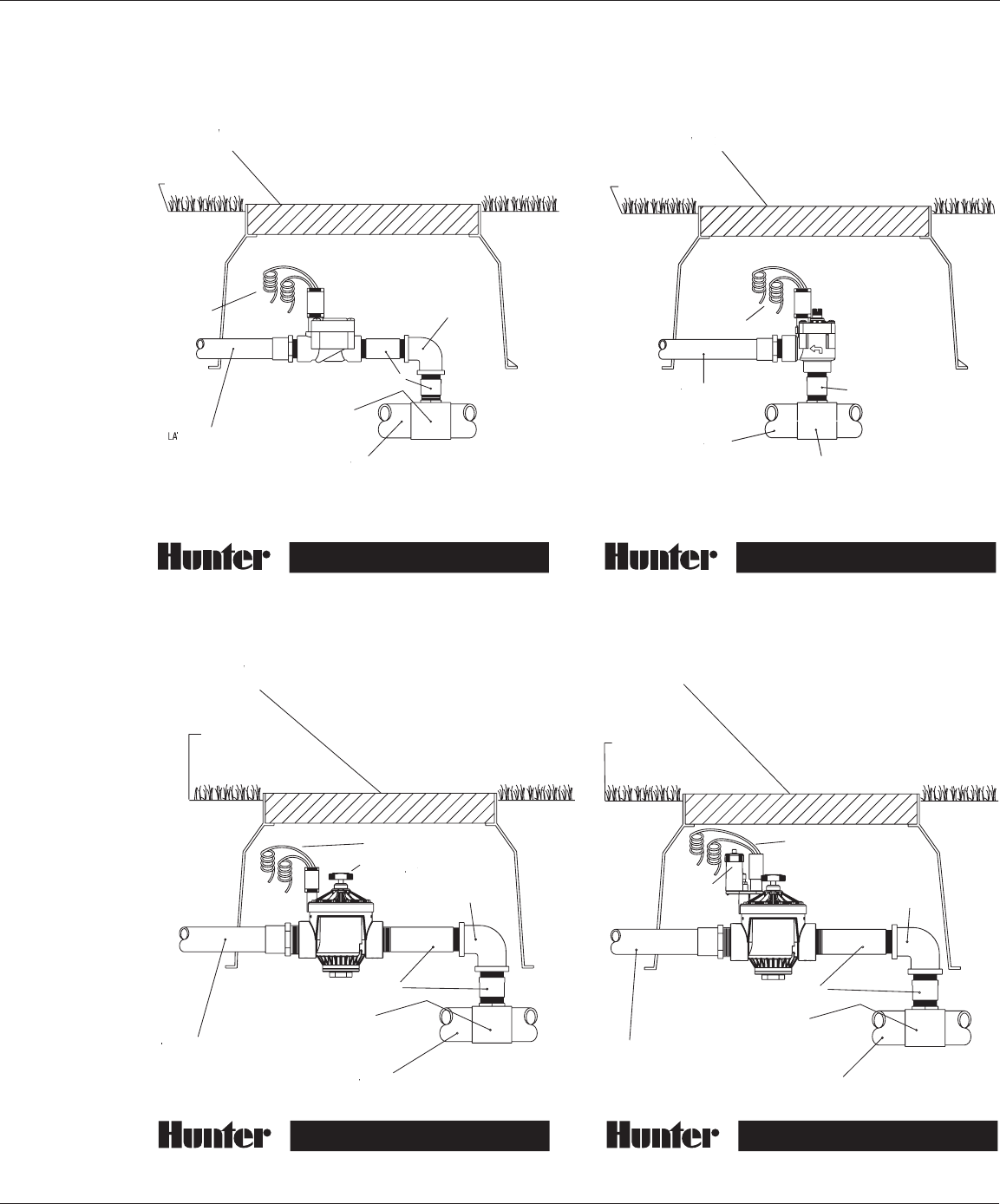
INSTALLATION DETAILS
2"PGVW/PR2" PGV-NP
1” PGV-ANGLE
®
LA
TERAL LINE
LA
LA
PLASTIC
VA
L
VE BO
LL
X
VE BO
VE BO
T
O SPRINKLERS
CONTR
OL
WIRE
SCHEDULE 80 PVC NIPPLE
MAIN LINE FITTING
MAIN SUPPL
Y LINE
MAIN SUPPL
MAIN SUPPL
FINISH GRADE
WITH CO
VER
1” PGV-GLOBE
®
TERAL LINE
LA
LA
PLASTIC
VA
L
VE BO
LL
X
VE BO
VE BO
T
O SPRINKLERS
CONTR
OL
WIRE
SCHEDULE 80
PVC NIPPLE
MAIN LINE FITTING
MAIN SUPPL
Y LINE
MAIN SUPPL
MAIN SUPPL
FINISH
GRADE
WITH CO
VER
90
°
ELL-PVC
® ®
LA
TERAL LINE
LA
LA
PLASTIC
VA
L
VE BO
LL
X
T
O SPRINKLERS
SCHEDULE 80 PVC NIPPLE
MAIN LINE FITTING
MAIN SUPPL
Y LINE
MAIN SUPPL
MAIN SUPPL
FINISH GRADE
WITH CO
VER
90
°
ELL-PVC
CONTR
OL
WIRE
LATERAL LINE
PLASTIC VALVE BOX
TO SPRINKLERS
SCHEDULE 80 PVC NIPPLE
MAIN LINE FITTING
MAIN SUPPLY LINE
FINISH GRADE
WITH COVER
90° ELL-PVC
CONTROL WIRE
PRESSURE
REGULATOR
RECLAIMED W
A
RECLAIMED W
RECLAIMED W
TER
A
A
IDENTIFICA
TION HANDLE
IDENTIFICA
IDENTIFICA

®
10
VALVE OPERATION
Basic Principles of Valve Operation
Water enters the valve from the system main
line and exerts a force against the center of
the valve’s diaphragm. A small orifi ce in the
diaphragm allows the water to fl ow through
to the upper chamber between the diaphragm
and the bonnet. The water continues to travel
on through a port in the bonnet to the solenoid
area. The solenoid has a light spring loaded
metal piston that, when the valve is closed,
covers the inlet port hole. The surface area
that the water comes in contact with on top
of the diaphragm is greater than the surface
area on the bottom of the diaphragm, so the
valve stays closed until the water in the upper
chamber is released. (pressure x area = force)
Electrically Opening a Valve
When the solenoid coil is electrically charged,
the current creates an electromagnetic fi eld
and pulls the piston off of the port hole seat
allowing water to fl ow into the solenoid
chamber, out of the solenoid exhaust port, and
into the downstream pipe. The solenoid ports
are larger than the orifi ce in the diaphragm,
so the water fl ows out of the upper diaphragm/
bonnet chamber faster than it is allowed
to enter. The pressure on the top of the
diaphragm is released through these ports, and
the force from the mainline side pushes against
the diaphragm and causes the valve to open.
Manually Opening a Valve
The same principle is at work when a valve
is manually opened using the manual bleed.
The pressure on the top of the diaphragm
is released through the use of an internal or
external bleed. The internal bleed on the PGV
mechanically lifts the solenoid piston off of
the upper chamber exhaust port allowing the
water to be released into the downstream pipe.
Some valves have an external bleed which
allows water to exit the upper diaphragm
chamber into the valve box.
Closing a Valve
When the controller turns off the low voltage
current fl ow, the solenoid piston spring pushes
the piston back over the inlet port, and stops
the fl ow of water from going through the
solenoid chamber and exhaust port. The upper
diaphragm/bonnet chamber begins to fi ll, and
soon reaches an equilibrium point when the psi
(pounds per square inch) is the same on both
sides of the diaphragm. The diaphragm spring
continues to gently push on the diaphragm,
closing the valve further. The combination of
the spring exerting pressure on the diaphragm
and the water building up in the upper
chamber bring the valve to a closed position.
11
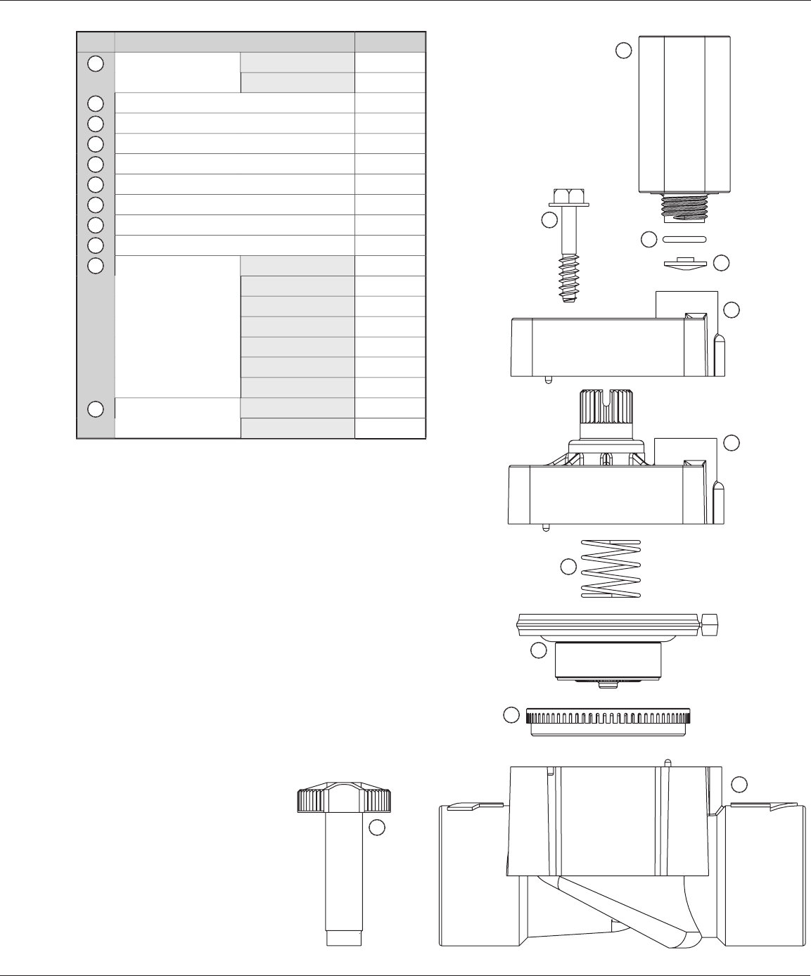
PGV-100G/101G: PLASTIC VALVES
1
2
3
4
5
6
7
8
9
10
10
10
11
11
11
Item
Description
Catalog No.
Solenoid Assembly
(Includes Parts 2 & 3)
AC Solenoid
434100
DC Solenoid
458200
O-Ring
262600
Solenoid Seal
364400
Bonnet Screw
427300
Bonnet without Flow Control
458000
Bonnet with Flow Control
435005
Diaphragm Spring
266000
Diaphragm Assembly
332100
Diaphragm Support Ring
331300
Body
Female, NPT Thread
457700
Female, BSP Thread
457705
Female, Slip x Slip
457710
Male x Male, NPT
433400
Male x Male, BSP
433405
Male x Barb, NPT
460700
Male x Barb, BSP
460705
Flow Control Handle
Black
269200
Purple
269205
10
10
10
6
7
8
9
11
11
11
1
2
3
4
5
12
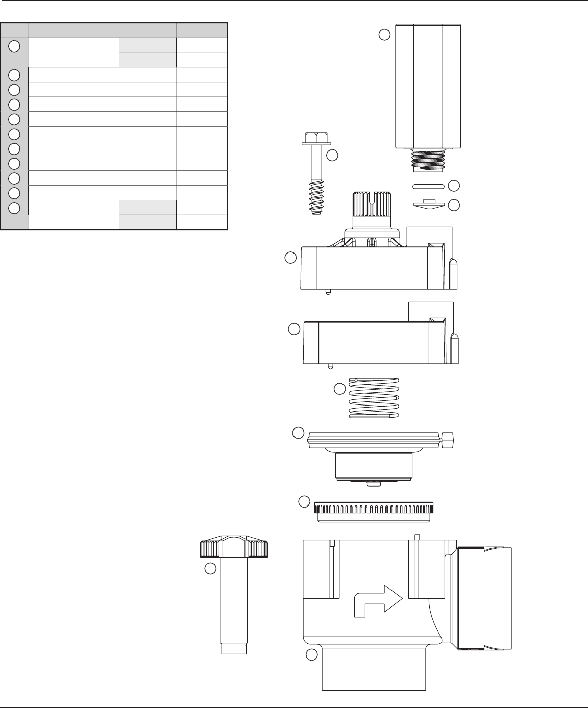
PGV-100A/101A: PLASTIC VALVES
Item
Description
Catalog No.
Solenoid Assembly
(Includes Parts 2 & 3)
AC Solenoid
434100
DC Solenoid
458200
O-Ring
262600
Solenoid Seal
364400
Bonnet Screw
427300
Bonnet with Flow Control
379405
Bonnet without Flow Control
435005
Diaphragm Spring
266000
Diaphragm Assembly
332100
Diaphragm Support Ring
331300
Body
407000
Flow Control Handle
Black
269200
Purple
269205
10
10
10
6
7
8
9
11
11
11
1
2
3
4
5
1
2
3
4
5
6
7
8
9
10
10
10
11
11
11

13
Item
Description
Catalog No.
Solenoid Assembly
(Includes Parts 2 & 3)
AC Solenoid
434100
DC Solenoid
458200
O-Ring
262600
Solenoid Seal
364400
Flow Control Handle Screw
334000
Flow Control Handle
Black
412700
Purple
412705
Bonnet Screw
472800
Bonnet
1½"
414000
2"
415500
Flow Control Stem
(Includes
O-Ring, Stem, Nut and Rod)
1½"
421500
2"
414600
Spring
1½"
412300
2"
414200
Diaphragm Assembly
1½"
414100
2"
415600
Diaphragm Support
1½"
413100
2"
414800
Body
1½" NPT
433200
1½" BSP
433205
2" NPT
433300
2" BSP
433305
Body Plug without O-Ring
1½" NPT
419200
1½" BSP
419205
2" NPT
419300
2" BSP
419305
Plug O-Ring
1½"
413900
2"
415400
10
10
10
6
7
8
9
11
11
11
12
12
12
13
13
13
14
14
14
1
2
3
4
5
PGV-151G, 201G: PLASTIC VALVES
1
2
3
4
5
6
8
9
10
10
10
11
11
11
12
12
12
14
14
14

14
ACCU-SET™
Item
Description
Catalog No.
Adjustment Knob
368500
O-Ring
262600
Inlet Seal
368200
1
2
3
1
2
3


®
Hunter Industries Incorporated • The Irrigation Innovators
© 2003 Hunter Industries Incorporated
1940 Diamond Street • San Marcos, California 92069 • TEL: (1) 760-744-5240 • FAX: (1) 760-744-7461
www.HunterIndustries.com
P/N 700651 LIT-294 1/03
