
ISO-NE PUBLIC
2050 Transmission Study
© ISO New England Inc.
Transmission Planning
FEBRUARY 12, 2024
2050 Transmission Study page iii
ISO-NE PUBLIC
Project Team
Peter Bernard
Reid Collins
Liam Durkin
Annie Kleeman
Andrew Kniska
Brent Oberlin
Dan Schwarting
Kannan Sreenivasachar
Marvin Valencia Perez
Pradip Vijayan
Supporting Departments:
Corporate Communications
External Affairs
Economic Studies & Environmental Outlook

2050 Transmission Study page iv
ISO-NE PUBLIC
Contents
Contents ....................................................................................................................................................................... iv
Figures .......................................................................................................................................................................... vi
Tables .......................................................................................................................................................................... vii
Section 1 : Study Overview ........................................................................................................................................... 8
1.1 Study Background and Objectives ....................................................................................................................... 8
Development of Study Objectives and Study-Specific Terms ...................................................................... 9
Source of Study Inputs for the Future Scenarios Examined......................................................................... 9
Summary of Input Assumptions for the Future Scenarios Examined ........................................................ 10
Practical Considerations and Limitations ................................................................................................... 13
1.2 Overview of the New England Transmission System ........................................................................................ 14
General Configuration of the New England Transmission System ............................................................ 14
Geographic Location and Types of Transmission Lines in New England.................................................... 15
Section 2 : Key Takeaways .......................................................................................................................................... 16
2.1 Reducing Peak Load Significantly Reduces Transmission Cost .......................................................................... 16
2.2 Targeting and Prioritizing High Likelihood Concerns is Highly Effective............................................................ 17
2.3 Incremental Upgrades Can Be Made as Opportunities Arise ............................................................................ 18
2.4 Generator Locations Matter .............................................................................................................................. 19
2.5 Transformer Capacity Is Crucial ......................................................................................................................... 19
Section 3 : High-Likelihood Concerns ......................................................................................................................... 21
3.1 High-Likelihood Concerns: North-South ............................................................................................................ 22
3.2 High-Likelihood Concerns: Boston Import......................................................................................................... 23
3.3 High-Likelihood Concerns: Northwestern Vermont Import .............................................................................. 25
3.4 High-Likelihood Concerns: Southwest Connecticut Import............................................................................... 26
Section 4 : Roadmaps and Representative Transmission Solutions .......................................................................... 27
4.1 North-South/Boston Import Roadmaps ............................................................................................................ 27
North-South/Boston Import Roadmap #1: AC Roadmap........................................................................... 27
North-South/Boston Import Roadmap #2: Minimization of New Lines Roadmap .................................... 28
North-South/Boston Import Roadmap #3: Point-to-point HVDC Roadmap .............................................. 29
North-South/Boston Import Roadmap #4: Offshore Grid Roadmap ......................................................... 30
Other Projects to Resolve Concerns in Boston .......................................................................................... 32
4.2 Northwestern Vermont Import Roadmaps ....................................................................................................... 33
Northwestern Vermont Import Roadmap #1: PV-20 Upgrade and Doubling of K-43 Roadmap ............... 33
Northwestern Vermont Import Roadmap #2: Coolidge-Essex Roadmap .................................................. 34
Northwestern Vermont Import Roadmap #3: New Haven-Essex and Granite-Essex Roadmap ................ 35

2050 Transmission Study page v
ISO-NE PUBLIC
Northwestern Vermont Import Roadmap #4: Minimization of New Lines Roadmap ............................... 36
4.3 Southwest Connecticut Import ......................................................................................................................... 37
4.4 Transformer Additions ...................................................................................................................................... 38
4.5 Other High-Likelihood Concerns........................................................................................................................ 39
4.6 Non-High-Likelihood Concerns .......................................................................................................................... 40
4.7 Map of All Transmission Upgrades and Additions ............................................................................................. 41
Section 5 : Cost of Transmission System Upgrades.................................................................................................... 46
5.1 Estimated Costs by Roadmap and Year ............................................................................................................. 48
Section 6 : Future Work .............................................................................................................................................. 57
Section 7 : Conclusion ................................................................................................................................................. 58
2050 Transmission Study page vi
ISO-NE PUBLIC
Figures
Figure 1-1: Load Levels Analyzed by Study Year .......................................................................................................... 11
Figure 1-2: Renewable Generation and Energy Storage Input Assumptions............................................................... 12
Figure 2-1: Costs by Year Studied ................................................................................................................................ 16
Figure 3-1: Line Mileage Overloaded in Boston with Generator Interconnection Locations Optimized..................... 25
Figure 4-1: North-South/Boston Import AC Roadmap ................................................................................................ 28
Figure 4-2: North-South/Boston Import Minimization of New Lines Roadmap .......................................................... 29
Figure 4-3: North-South/Boston Import Point-to-Point HVDC Roadmap .................................................................... 30
Figure 4-4: Boston Import Offshore Grid Roadmap..................................................................................................... 32
Figure 4-5: Northwestern Vermont Import PV-20 Upgrade and Doubling of K-43 Roadmap ..................................... 34
Figure 4-6: Northwestern Vermont Import Coolidge-Essex Roadmap ........................................................................ 35
Figure 4-7: Northwestern Vermont Import New Haven-Essex and Granite-Essex Roadmap...................................... 36
Figure 4-8: Northwestern Vermont Import Minimization of New Lines Roadmap ..................................................... 37
Figure 4-9: Southwest Connecticut Import Transmission Additions ........................................................................... 38
Figure 4-10: Transmission Upgrades and Additions for the Coolidge -Essex Roadmap and the AC Roadmap ........... 42
Figure 4-11: Transmission Upgrades and Additions for the Minimization of New Lines Roadmaps ........................... 43
Figure 4-12: Transmission Upgrades and Additions for the PV-20 Roadmap and the DC Roadmap........................... 44
Figure 4-13: Transmission Upgrades and Additions for the New Haven - Essex Roadmap and the Offshore Grid
Roadmap...................................................................................................................................................................... 45
Figure 5-1: Estimated Cumulative Costs for North-South/Boston Import Roadmaps ................................................. 49
Figure 5-2: Cost Categories for North-South/Boston Import Roadmaps: 51 GW Winter Peak ................................... 50
Figure 5-3: Cost Categories for North-South/Boston Import Roadmaps: 57 GW Winter Peak ................................... 50
Figure 5-4: Estimated Cumulative Costs for Northwestern Vermont Import Roadmaps ............................................ 51
Figure 5-5: Cost Categories for NWVT Import Roadmaps: 51 GW Winter Peak.......................................................... 52
Figure 5-6: Cost Categories for NWVT Import Roadmaps: 57 GW Winter Peak.......................................................... 52
Figure 5-7: Total Costs by Year Studied ....................................................................................................................... 56
2050 Transmission Study page vii
ISO-NE PUBLIC
Tables
Table 3-1: Miles of Transmission Lines Overloaded in the Boston Subregion by Snapshot Year/Load ....................... 24
Table 4-1: Transformer Overloads by Snapshot Year, Pre- and Post-Optimization..................................................... 39
Table 5-1: Cost Assumptions for 2050 Transmission Study Upgrades......................................................................... 47
Table 5-2: Cost Assumptions for Offshore Grid Components...................................................................................... 48
Table 5-3: Estimated Cumulative Costs for North-South/Boston Import Roadmaps .................................................. 49
Table 5-4: Estimated Cumulative Costs for Northwestern Vermont Import Roadmaps ............................................. 51
Table 5-5: Estimated Cumulative Costs for Southwest Connecticut Import ............................................................... 53
Table 5-6: Estimated Cumulative Costs for Miscellaneous High-Likelihood Concerns ................................................ 53
Table 5-7: Estimated Cumulative Costs for Non-High-Likelihood Concerns ................................................................ 54
Table 5-8: Estimated Cumulative Costs by Year Studied ............................................................................................. 55

2050 Transmission Study page 8
ISO-NE PUBLIC
Section 1: Study Overview
The New England power system is in the midst of an unprecedented shift in the ways in which
electricity is produced and consumed. Five of the six New England states have committed to
reducing their carbon dioxide emissions by at least 80% by 2050, prompting ongoing changes in
the grid’s resource mix and the increased electrification of the heating and transportation sectors.
1
Driven largely by these statewide commitments, the grid continues its shift toward renewable
resources like wind and solar photovoltaic (PV) generation. Over the next several decades, these
renewable resources are expected to substantially displace natural gas-fired generation as the
region’s primary resource type. At the same time, increased electrification is expected to
significantly increase overall consumer demand for electricity and drive changes in usage patterns
that include seasonal and daily shifts in peak demand.
Among ISO New England’s responsibilities as a Federal Energy Regulatory Commission (FERC)-
authorized Regional Transmission Organization is ensuring the regional power system continues to
operate reliably as system conditions change. Transmission planning helps to maintain system
reliability and enhance the region’s ability to support a robust, competitive wholesale power
market by moving power from various internal and external sources to the region’s load centers.
This 2050 Transmission Study is a pioneering look at the ways in which the transmission system in
New England may be affected by changes to the power grid, and includes roadmaps designed to
assist stakeholders in their efforts to facilitate a smooth, reliable clean energy transition.
1.1 Study Background and Objectives
In October 2020, the New England States Committee on Electricity (NESCOE) released the New
England States’ Vision for a Clean, Affordable, and
Reliable 21st Century Regional Electric Grid. This vision
statement recommended that the ISO work with
stakeholders to conduct a comprehensive long-term
regional transmission study. This study, eventually
titled the 2050 Transmission Study, would help inform
stakeholders of the amount and type of transmission
infrastructure necessary to provide reliable, cost-
effective energy to the region throughout the clean
energy transition.
In response to NESCOE’s vision statement, the ISO
revised Attachment K to the
ISO New England Open
Access Transmission Tariff to incorporate a new
transmission planning process designed to look beyond
the current 10-year planning horizon. The first phase of the effort established the rules that will
allow New England states, through NESCOE, to request that the ISO perform longer-term scenario-
based transmission planning studies, such as this one, on a routine basis. Changes to the ISO Tariff
were approved by FERC in early 2022. The 2050 Transmission Study is the first example of its kind
within New England.
1
The six New England states are Connecticut, Maine, Massachusetts, New Hampshire, Rhode Island, and Vermont. The five
states with the emissions reduction goals described here are Connecticut, Maine, Massachusetts, Rhode Island, and Vermont.
Who is NESCOE? NESCOE is a not-
for-profit entity that represents the
collective perspective of the six New
England Governors in regional
electricity matters and advances
the New England states’ common
interest in the provision of
electricity to consumers at the
lowest possible prices over the long-
term, consistent with maintaining
reliable service and environmental
quality.

2050 Transmission Study page 9
ISO-NE PUBLIC
The longer-term transmission study process is currently informational. The process does not
include a formal mechanism for triggering the construction of a new transmission project.
However, the ISO is currently discussing the second phase of the longer-term transmission study
Tariff changes that will establish a process to enable the states, through NESCOE, to move policy-
related transmission projects forward, with an associated cost allocation. This effort began at
stakeholder meetings in October 2023, and will continue through early 2024.
Development of Study Objectives and Study-Specific Terms
In 2021, the ISO began coordination with NESCOE to develop objectives and assumptions for this
study.
The 2050 Transmission Study has two main objectives:
• Determine the region’s transmission needs in order to serve load while satisfying North
American Electric Reliability Corporation (NERC), Northeast Power Coordinating Council
(NPCC), and ISO reliability criteria.
2
• Develop roadmaps for transmission upgrades designed to satisfy those needs while
considering both the feasibility of construction and cost.
In this study, the term roadmap is intended as a high-level plan designed to show generally how
transmission-related objectives can be accomplished. The roadmaps provided in this study are not
intended as comprehensive or detailed plans for construction. They include:
• Conceptual projects specific to the input assumptions of the study.
• Concerns defined as high-likelihood; projects that address these concerns are considered
useful to the region because they are less dependent on the specific locations of generation
and supply to load.
• Lessons learned that can be applied to future long-term transmission studies.
Source of Study Inputs for the Future Scenarios Examined
The future scenarios envisioned by NESCOE included load forecasts and potential resource mixes
for the years 2035, 2040, and 2050 that were based on the All Options Pathway in
Massachusetts’
Deep Decarbonization Roadmap report, published in December 2020. This Pathway was also used
in the ISO’s recent Future Grid Reliability Study Phase 1 (FGRS), referred to in FGRS as Scenario 3.
This future scenario will be referred to in this report as the All Options Pathway.
The All Options Pathway provided two types of data input for the 2050 Transmission Study: 1) New
England’s expected hourly loads for all hours in a year for 2035, 2040, and 2050 and 2) renewable
and conventional energy capacity for the same years. This data was combined with hourly wind and
solar production data developed by an advisory firm, DNV, for various locations in New England to
create year-round hourly profiles of renewable generation output.
3
Using this data, the ISO
developed “snapshots” for the years studied, which combined load and resource profiles for
contingency analysis. Contingencies are unexpected events that affect the flow of power on the
transmission system, such as the loss of a transmission line, a transformer, or certain types of
2
Load is defined as the demand for electricity measured in megawatts; electricity consumption; the amount of electric power
delivered to any specified point on a system, accounting for the requirements of the customer’s electrical equipment.
3
For further details on the data set created by DNV, please see the “Variable Energy Resource (VER) Data” page on the ISO-NE
website.

2050 Transmission Study page 10
ISO-NE PUBLIC
substation equipment. This contingency analysis was designed to test peak load boundary
conditions, which represent the most extreme or severe cases of combined load and renewable
resource output that could realistically be expected to occur. An example of a boundary condition
would be a particularly cold winter peak hour, corresponding with high loads, in which weather
conditions resulted in low renewable resource production. Essentially, boundary conditions in this
study were designed to represent the realistic “worst case scenario” for future transmission
planning needs related to serving peak loads.
It is important to note that all conceptual projects in this 2050 Transmission Study are formulated
from one particular pathway among the eight mentioned in the MA Deep Decarbonization
Roadmap. Changing inputs to the No Thermal Pathway, or the 100% Renewable Pathway, for
example, would impact the conceptual projects list.
4
It is likely that the future power system will
differ from the assumptions found in the All Options Pathway. As an example, the expected
nameplate capacity of battery energy storage for 2030 has already exceeded the All Options
Pathway’s assumptions for 2035. As the system evolves, the quantity and location of generating
resources and load will likely lead to differences between reality and this study’s results. However,
this study’s key takeaways and high-likelihood concerns still represent crucial high-level
directional results that can be used by stakeholders to plan for a smooth clean energy transition.
Summary of Input Assumptions for the Future Scenarios Examined
The first input taken from the All Options Pathway was the hourly load for each snapshot year,
which was then recast from a 2012 weather year to a 2019 weather year.
5
The next inputs were the
highest-load hours from the winter and summer periods. For winter periods, each state in New
England was at or near its own peak load while New England as a whole was at its overall peak
load, so a single snapshot in time captured worst-case or near-worst-case conditions in all six
states. For summer periods, three varieties of peak loads were chosen in order to ensure the study
captured the most severe conditions for each part of New England. The first was a summer daytime
peak condition, intended to represent a period when total power consumption is highest. This
condition is likely to be most pronounced in areas with little behind-the-meter solar penetration,
such that solar power production cannot offset the hottest mid-day temperatures. The two
remaining conditions used as summer period inputs were evening peak conditions, where the total
load served by the transmission system (end-user load less any reductions for behind-the-meter
solar) was greatest. During summer evenings, load decreases due to slightly lower consumption,
but behind-the-meter solar production is low or zero. Hence, net load is greatest during this time.
The All Options Pathway data showed that the three northern New England states (Maine, New
Hampshire, and Vermont) tended not to peak at the same time as the region as a whole. To ensure
that the worst-case conditions for the northern states were captured, a second summer evening
peak snapshot was created, reflecting the hour in which load served from the transmission system
was highest in the three northern states.
The resulting loads in each snapshot were significantly higher than any loads seen to-date in New
England, and rose significantly from 2035 to 2040 and from 2040 to 2050. The highest load
modeled was the 2050 winter evening peak snapshot, at approximately 57 gigawatts (GW). For
4
The No Thermal Pathway assumed all thermal capacity retired by 2050; the 100% Renewable Pathway assumed no fossil fuels
allowed, with zero-carbon combustion fuels allowed for electricity generation by thermal power plants.
5
For further details on the reasons for this recasting and the process used, please see slide 11 of the following presentation:
https://www.iso-ne.com/static-
assets/documents/2021/04/a8_2021_economic_study_request_assumptions_part_1_rev2_clean.pdf

2050 Transmission Study page 11
ISO-NE PUBLIC
comparison, the highest load observed to date on the New England system was the 2006 summer
peak of just over 28 GW, and the highest winter load observed to date was the January 2004 peak of
just below 23 GW. The loads analyzed in each year studied are shown in Figure 1-1.
Figure 1-1: Load Levels Analyzed by Study Year
These loads were assumed to be served by a generation fleet that differs significantly from today’s
resource mix. All coal, oil, diesel, and municipal solid waste-fueled generation, as well as a portion
of today’s natural-gas-fueled generation, was assumed retired by 2035, the earliest year studied.
The remainder of today’s natural-gas-fueled generation, as well as biomass, nuclear, hydroelectric,
and renewable generators, were assumed to remain operational through 2050. The retired
generation, as well as the increases in load, were assumed to be offset by a significant increase in
wind and solar generation, as well as battery energy storage and increased imports from
neighboring power systems in New York and Québec. Much of this increased wind capacity is
located offshore, either off the coast of southeastern Massachusetts and Rhode Island, or in the Gulf
of Maine. Figure 1-2 shows the growth in renewable generation and energy storage assumed as
inputs for this study.
29 GW
35 GW
32 GW
43 GW
40 GW
57 GW
0
10,000
20,000
30,000
40,000
50,000
60,000
Summer Winter Summer Winter Summer Winter
2035 2040 2050
Megawatts
Transportation
Heating/Cooling
Other Load
28 GW
All-time peak
23 GW
Winter
record peak

2050 Transmission Study page 12
ISO-NE PUBLIC
Figure 1-2: Renewable Generation and Energy Storage Input Assumptions
While the All Options Pathway specified a total amount of each generation type by state,
transmission planning studies like the 2050 Transmission Study require location data on a more
granular level. Exact generator location is needed to develop useful results. In this study, new
offshore wind generation was initially assumed to interconnect at major 345 kilovolt (kV)
substations near the coast of New England, in order to minimize the length of cables between the
interconnection points and offshore wind locations. As the study progressed, some of these
interconnection points were relocated in order to eliminate transmission system concerns to the
extent possible without changing the total amount of generation in each state (see section 2.4 for
further details on generator relocation decisions). Similarly, energy storage facilities were initially
assumed to interconnect at major 345 kV stations, but were later relocated within the same state to
reduce transmission concerns where possible. Many of these relocations were from 345 kV stations
to 115 kV stations. Finally, solar generation was distributed evenly across each 115 kV substation in
each state, with certain substations in densely populated areas excluded due to the lack of available
land.
In addition to generation located within New England, the All Options Pathway assumed that New
England would import power to serve some of its peak load needs from neighboring areas. The
following inter-area imports were part of the All Options Pathway and were used in all snapshots
examined in this study:
• 1,000 MW imported from New Brunswick over existing 345 kV AC ties.
• 1,850 MW imported from New York over the existing 345 kV, 230 kV, 115 kV, and 69 kV AC
ties.
13.6
23.7
31.5
57
2.5
9.4
16.6
32
1.5
3 3 3
2
0.9
1.4
5.2
0
10
20
30
40
50
60
Solar Offshore Wind Onshore Wind Battery Storage
Nameplate capacity (gigawatts)

2050 Transmission Study page 13
ISO-NE PUBLIC
• 1,400 MW imported from Quebec over the existing Phase II HVDC tie (interconnected at
Sandy Pond substation in Ayer, Massachusetts).
• 225 MW imported from Quebec over the existing Highgate HVDC back-to-back converter
(interconnected in Highgate, Vermont).
• 1,200 MW imported from Quebec over the under-construction New England Clean Energy
Connect HVDC tie (interconnecting at Larrabee Road substation in Lewiston, Maine).
• 1,000 MW imported from Quebec over a hypothetical new HVDC tie between Quebec and
Vermont (assumed to interconnect at the Coolidge substation in Cavendish, Vermont).
Practical Considerations and Limitations
Three major practical considerations were applied to this study and are important to note when
interpreting study results. First, analysis is restricted to thermal steady-state analysis, which
identifies thermal overloads that could only be solved by major transmission additions or upgrades.
Thermal overloads occur when transmission lines, transformers, or certain substation equipment
carries more than its rated amount of current or power flow. This condition can lead to
overheating, equipment disconnection, or, in some cases, permanent damage. Analysis of voltage,
short circuit or transient stability performance was omitted, and will need to be explored in future
studies. This simplification allowed the study team to quickly identify major transmission line and
transformer additions, which are usually more expensive and harder to site than the substation
upgrades typically required for voltage, short circuit, or transient stability needs.
Second, analysis in this study is limited to transmission needs and conceptual transmission
projects. Significant upgrades to the distribution systems will be necessary to accommodate a 2050
peak load that will be roughly double what New England has historically experienced. This
anticipated expansion of the distribution system or the sub-transmission infrastructure is beyond
the scope of this study, and will likely add significant costs to the evolution of the power system.
This consideration required a simplification by modeling all loads at substations operated at 69 kV
and above rather than at the lower voltage substations at which they actually connect.
The third and final practical consideration involves resource adequacy. This study found that the
resource quantities assumed by the All Options Pathway, when combined with the resource
availability assumptions made by the ISO, were insufficient to meet the snapshot loads for the
Summer Evening and Winter Evening Peaks of 2035, 2040 and 2050. The largest observed shortfall
was roughly 12,000 MW in the 2050 57 GW Winter Peak snapshot. In order to conduct analysis of
the transmission system during these snapshots and ensure the model could run, shortfall MWs
were added as needed in order to meet load.
6
These shortfall MWs were added at offshore wind
points of interconnection (POIs). Future work will be needed to determine more specifically how
shortfalls will be resolved. For the purposes of this study, the added shortfall MWs can be thought
of as more offshore wind (either higher output or higher installed capacity), battery storage that
charges from excess wind during times of high production and discharges when wind production is
lower, or additional imports from regions outside of New England through a hypothetical inter-area
offshore grid.
6
For further details, please see the November 2021 presentation on the 2050 Transmission Study scope of work.
2050 Transmission Study page 14
ISO-NE PUBLIC
1.2 Overview of the New England Transmission System
This section is designed as a primer for those unfamiliar with the New England transmission
system. Those readers who are more familiar with transmission planning are invited to skip ahead
to Section 2.
General Configuration of the New England Transmission System
ISO New England is responsible for the long-term planning of the networked portions of the high-
voltage transmission system (known in New England as the Pool Transmission Facilities, or PTF),
and this study was performed in support of this objective.
7
The role of the electric transmission
system is to efficiently deliver electricity over long distances, from generation within New England
or imports from adjacent areas, to connections to local distribution systems. The transmission
system is a networked grid of high-voltage transmission lines and transformers, with electric power
naturally distributing itself among many parallel paths according to the locations of supply
(generation/imports), demand (load), and electrical characteristics of the high-voltage
transmission lines and transformers. Substations, found at the intersection of transmission lines,
handle switching, protection, and transformation from one voltage level to another. At many of
these substations, transformers step power down from higher transmission voltages, typically 69
kV and above, to distribution voltages below 69 kV. Local transmission owners and distribution
companies, rather than the ISO, are responsible for the planning of any radial portions of the
transmission system (which have only a single connection to the rest of the transmission system),
the transmission-distribution interface, and the distribution systems.
The future evolution of the power system toward renewable and variable or intermittent resources
increases the importance of a robust transmission system. Many of the best locations for renewable
resources like large-scale wind and solar farms are not near major load centers (i.e., the urban
areas of New England) and the transmission system will be relied on to deliver the power from
these renewable resources to electricity consumers. While distributed resources, such as rooftop
solar, can be located in more populated areas, the transmission system still helps bring power into
these areas during nighttime periods or other times when intermittent renewable resources’
output is not sufficient to meet the local load. Transmission can also help to provide geographic
diversity in renewable resources, smoothing out variations in wind and solar production in
different parts of the power system. Finally, with the expected future increase in the electrification
of the heating and transportation sectors, summer and winter peak loads are expected to increase
dramatically. Additionally, New England’s current summer peaking system is forecasted to become
winter peaking by the mid 2030s. A robust transmission system will ensure that loads under these
future conditions can be served reliably.
New England’s power system provides electricity to diverse geographic areas, ranging from rural
communities to densely populated cities. The majority of consumer demand, roughly 77%, is
located in the southern states of Massachusetts, Connecticut, and Rhode Island.
8
Although the land
area in the northern states is larger, the greater urban development in southern New England
creates greater demand and corresponding transmission density. However, it is the larger areas of
land in northern New England that offer greater potential for renewable power generation. Today,
7
An exact definition of the New England PTF may be found in section II.49 of the ISO New England Open Access Transmission
Tariff.
8
The distribution of loads between the New England states can vary from month to month, day to day, and hour to hour.
Values cited are seasonal approximations.

2050 Transmission Study page 15
ISO-NE PUBLIC
flows on the transmission system are primarily from west to east and from north to south.
However, flows change throughout each day, and the predominant flows will change significantly
by 2050 due to additional new renewable generation and significant load growth. Because the
demands on the New England transmission system can vary widely, the system must at all times be
able to reliably move power from various internal and external sources to the region’s load centers
under a wide-ranging set of conditions. Included in these conditions are contingencies. The exact
lists of contingencies that must be analyzed are set by reliability standards created by the North
American Electric Reliability Corporation (NERC), the Northeast Power Coordinating Council
(NPCC), and the ISO. In accordance with these standards, the 2050 Transmission Study examines
“N-0” conditions (all facilities in-service), “N-1” conditions (single contingency), and “N-1-1”
conditions (two consecutive contingencies, with time for manual system readjustments between
contingencies).
Geographic Location and Types of Transmission Lines in New England
The New England transmission system consists of mostly 115, 230, and 345 kilovolt (kV)
transmission lines, which are generally longer and fewer in number in northern New England than
in the southern states.
9
The region has 13 interconnections with neighboring power systems in the
United States and eastern Canada. Nine interconnections are with New York (NYISO)—two 345 kV
ties; one 230 kV tie; one 138 kV tie; three 115 kV ties; one 69 kV tie; and one 330-megawatt (MW),
±150 kV high-voltage direct-current (HVDC) tie, the Cross-Sound Cable interconnection. New
England and the Maritimes (New Brunswick Power Corporation) are connected through two 345
kV alternating current (AC) ties.
10
New England also has two HVDC interconnections with Québec
(Hydro-Québec, or HQ). One is a 120 kV AC interconnection with a 225 MW back-to-back converter
station (Highgate in northern Vermont), which converts AC to direct current (DC) and then back to
AC. The second is a ±450 kV HVDC line with terminal configurations allowing up to 2,000 MW to be
delivered at Sandy Pond in Massachusetts (Phase II).
9
Detailed maps and diagrams of the New England transmission system may be found on ISO-NE’s website, at https://www.iso-
ne.com/about/key-stats/maps-and-diagrams.
10
One exception is that Aroostook County and part of Washington County in Maine receive electricity from New Brunswick,
and are administered by the Northern Maine Independent System Administrator (NMISA) rather than ISO New England.

2050 Transmission Study page 16
ISO-NE PUBLIC
Section 2: Key Takeaways
The 2050 Transmission Study resulted in several high-level observations related to transmission-
related challenges the future grid may face as a result of the clean energy transition. These key
takeaways are detailed in the following subsections. They are:
1. Reducing peak load significantly reduces transmission cost.
2. Targeting and prioritizing high likelihood concerns is highly effective.
3. Incremental upgrades can be made as opportunities arise.
4. Generator locations matter.
5. Transformer capacity is crucial.
2.1 Reducing Peak Load Significantly Reduces Transmission Cost
Increases in load become significantly more expensive (with regard to transmission costs) as peak
load levels increase. This is especially true at levels above ~51 GW of load.
11
Increases in load at
peak load levels below 51 GW do increase costs (roughly $0.75 billion per GW of load added from
28 GW to 51 GW), but these increases are small when compared to the increase in costs above 51
GW of load (roughly $1.5 billion per GW of load added from 51 GW to 57 GW). Figure 2-1 shows the
approximate cost required for transmission expansion to serve load reliably in each year studied.
Figure 2-1: Costs by Year Studied
Limiting load growth to no more than a 51 GW peak load level could be achieved in several different
ways. A 2050 New England grid with 100% heating and transportation electrification is expected to
result in a ~57 GW peak load. However, a 51 GW peak could be achieved under a scenario in which
11
This subsection concentrates on winter peak loads, which are the highest loads in the 2050 Transmission Study. These winter
peak loads occur after sunset, so there is no difference between “gross load,” or the actual amount of power consumed by end
users before reductions due to rooftop solar, and “net load,” or the load served by the transmission system after these
reductions.
$0 B
$5 B
$10 B
$15 B
$20 B
$25 B
Range for 51
GW peak in
2050
Estimated cost
Range for 57
GW peak in
2050
43 GW
2040
35 GW
2035
Low estimate
High estimate

2050 Transmission Study page 17
ISO-NE PUBLIC
New England retains some stored fuels like natural gas, oil, propane, hydrogen, etc. for heating and
transportation. Since loads above 51 GW would only occur during extremely cold winter days, peak
load could be limited to 51 GW in a scenario in which the grid is 100% electrified for most of the
year, with only the coldest days using some stored fuels for heating. If the full 6 GW of load
reduction came out of heating, this could still represent approximately 80% heating electrification
while still maintaining 100% transportation electrification.
Alternately, more aggressive demand response (when customers reduce their electrical
consumption for compensation) and peak shaving programs (e.g., smart thermostats that reduce
the set temperature during a winter peak time) that could shift load to times of lower demand may
also help maintain a 51 GW peak load level, thereby reducing transmission costs. The extent of
these forms of load reduction would need to be in addition to those already assumed by the “All
Options” pathway, which considered that 50% of electric vehicle charging load, 15% of space
heating/cooling load, and 25% of water heating load could be shifted. Work from other studies,
however, including Economic Planning for the Clean Energy Transition
(EPCET), have shown a
potential overall energy deficit in the winter months whether these strategies are deployed or not.
Since shifting MWs to other hours of the day would still lead to an overall energy shortfall, the total
MWhs consumed in the winter months may still need to be reduced. Reducing load by shifting
energy from peak hours to off-peak hours on the same day would help address transmission costs
but would not address energy adequacy concerns over longer periods of days or weeks. More
aggressive energy efficiency programs (such as incentivizing customers to install better insulation
in their homes/businesses, and/or upgrade appliances and heat pumps, etc.) are among the options
that could be considered in order to maintain a 51 GW peak load while still achieving electrification
goals.
Public education and involvement may be an important factor in modifying consumer behavior to
reduce electricity demand at key times. Consumer awareness of the nature and timing of peak load
may help consumers participate in the reduction of peak loads to more manageable levels, which
could save billions of dollars in transmission system upgrade costs.
2.2 Targeting and Prioritizing High Likelihood Concerns is Highly Effective
One major outcome of the 2050 Transmission Study was the identification of system concerns that
could be resolved through transmission system expansion and could appear under a wide variety of
possible future conditions. This wide variety of conditions, detailed in Section 3, include different
load levels, different generator locations, and differing rates of load growth at particular
substations. This report describes a number of high-likelihood concerns that appear to meet these
conditions. While this study examined just one of many possible futures for the New England power
system, and of that possible future examined only certain hours of the year when electricity
consumption is expected to be at its highest, these results can still be used to infer which areas of
the transmission system are likely to be most limiting as the system evolves.
Projects that address these high-likelihood concerns are likely to bring the greatest benefit for a
wide range of possible future conditions as the clean energy transition accelerates. The
assumptions used for future load and generation patterns include a fair amount of uncertainty, but
these high-likelihood concerns are likely to appear even under somewhat different future
conditions. Targeting these concerns should be considered higher-priority than other potential
challenges identified in the 2050 Transmission Study, which would likely occur only if generators
interconnect at specific locations or if load grows in specific patterns.

2050 Transmission Study page 18
ISO-NE PUBLIC
In an effort to identify high-likelihood concerns and other transmission overloads, the locations of
new generator interconnections were optimized, within reason. By locating these interconnections
so as to minimize transmission overloads observed under peak load conditions, any remaining
overloads would likely only be solved through transmission expansion. Concerns that could be
alleviated by new generation interconnections (within the bounds of the total amounts of
generation in each New England state assumed for this study) are therefore not included in the
results because they were resolved by the change of generation interconnection location.
2.3 Incremental Upgrades Can Be Made as Opportunities Arise
Many of the transmission system concerns identified in the 2050 Transmission Study could be
addressed by rebuilding existing transmission lines with larger conductors, rather than expanding
the transmission system into new locations. In many cases, replacing transmission lines with larger
conductors and increasing their power transfer capability would allow the system to serve
significantly higher peak loads. This type of conductor replacement, or reconductoring, may also
require replacing some or all of a transmission line’s structures in order to accommodate heavier,
larger conductors. Advanced conductor technologies that may be able to make use of existing
structures while still delivering higher ratings and lower losses could also be considered.
Additionally, other incremental upgrades could be beneficial; examples include bundling multiple
conductors per phase on 115 kV lines (already a common practice on 345 kV lines in New England)
or rebuilding transmission lines to allow for a higher operating voltage.
Limiting brand new line construction by taking advantage of line rebuilds could minimize costs,
especially in densely populated areas in southern New England. In many areas, expanding existing
rights-of-way or constructing new rights-of-way could be difficult, expensive, and environmentally
disruptive, and thus maximizing the use of existing rights-of-way is critical to the success of the
region’s transmission system reliability through the clean energy transition.
While these incremental upgrades should be considered crucial to the improvement of New
England’s transmission system, it is not necessarily prudent for the region to pursue large numbers
of line rebuilds immediately. Many of these line rebuilds are highly dependent on the locations of
generator interconnections, the geographic distribution of end-user load, and the locations of new
load-serving substations. Since these incremental upgrades can generally be built in a shorter
timeframe than new transmission on new rights-of-way, it may be more practical to address these
incremental needs via the traditional ten-year reliability planning process rather than the longer-
term planning process that prompted this study. This strategy would allow the region to hold off on
committing to further transmission system investment until new information is available, and also
provide opportunities for more cost-effective “right-sizing” transmission projects.
“Right-sizing” is a term used to describe combining line rebuilds necessitated by increased loads
with replacements designed to meet asset condition needs. In New England, asset condition
projects are identified by transmission owners when equipment exceeds its useful life. Since a
significant portion of New England’s transmission system was developed in the mid-20
th
century,
many transmission lines are beginning to reach the end of their life and must be replaced. During
such an asset condition replacement project, the incremental cost of upgrading a transmission line
to a larger conductor size and stronger structures is relatively low. Many expenses inherent in
transmission line rebuilds are unrelated to the line’s capacity; costs related to building access roads
along a right-of-way, labor for building structures, and financing an ongoing project are not
significantly affected by the size of the conductor chosen. Therefore, upgrading the capacity of lines
as the opportunity arises, or “right-sizing” asset condition projects when they occur, could be a

2050 Transmission Study page 19
ISO-NE PUBLIC
financially prudent way for New England to reliably serve increased peak loads. Further
discussions between the ISO, the Transmission Owners, and NESCOE on “right-sizing” asset
condition projects will continue at the Planning Advisory Committee in 2024 in order to inform the
region of the possible economic advantages of these opportunities more fully.
2.4 Generator Locations Matter
The 2050 Transmission Study also found that the specific location of generators can have a
significant impact on the transmission upgrades required for reliability. The study attempted to
optimize, within reason, new generator locations for offshore wind, solar photovoltaics (PV), and
batteries in import-constrained regions to reduce the number and severity of overloads
experienced while serving peak loads. As a result, the overloads observed were those that persisted
in spite of these optimized generation locations. Locating generators in suboptimal areas would
likely significantly worsen the overloads, particularly in import-constrained regions like Boston.
Optimizing generation locations is also crucial for determining which lines must be upgraded, since
a generator could either push back on heavy flows toward load centers or contribute to even higher
loading on transmission lines, depending on the location of its interconnection. Essentially, locating
generators closer to large population hubs will help reduce the strain on the transmission system,
since the cumulative distance power must flow to reach electricity consumers will be greatly
reduced.
Generator location is less important for some of the larger-scale upgrades like new major lines
leading from northern New England to southern New England. Whether a generator is placed at
one substation in Maine or at a different station 10 miles away matters very little, since the majority
of the power from that generator will ultimately flow from Maine into southern New England
regardless of the generator’s exact location. As long as generators in northern New England are
located in the general vicinity of the terminal of a large-scale upgrade, the exact substation where
they interconnect is not as critical.
2.5 Transformer Capacity Is Crucial
Increasing electrification results in load growth, which then requires more renewable resources to
be added to the New England power system. This increase in load and generation can strain the
existing transformer capacity within New England, particularly the 345/115 kV transformers.
Transformers must reliably “step down” power from higher to lower transmission voltages, and the
2050 Transmission Study revealed that existing transformers across the system were frequently
unable to do so without thermal overloads. Between 2035 and 2050, the assumed load increased
significantly across the region, in tandem with the increase in generation located farther from load
centers. This trend increases the importance of higher voltage lines such as the 345 kV system to
transfer power over long distances. Throughout all snapshot years, transformers created choke
points, since the system’s existing transformers were not originally designed to handle the large
loads assumed in this study.
As described in the previous key takeaway, generator locations matter. When generation location
was optimized in order to locate more generation on the 115 kV system closer to the load, rather
than on the 345 kV system, transformer overloads were reduced.
Results from the 2050 Transmission Study reveal that the power system is only as reliable as its
ability to deliver power through transformers without experiencing overloads. One benefit of
higher voltage transmission (in New England, primarily 345 kV) is its increased capacity to transfer
2050 Transmission Study page 20
ISO-NE PUBLIC
more power across long distances while minimizing losses of power along the way. However, this
additional power transferred along higher voltage lines must eventually “step down” to 115 kV via
transformers on its way to distribution substations fed by 115 kV lines, and these transformers
must be able to support the increase in load and power injection. Results from the studied
snapshots show that the existing transformer fleet will not be able to adequately support future
power flows from the 345 kV to the 115 kV system. This is not an issue with the transformers
themselves, but rather is a predictable consequence of increases in load and the fact that this
increased load is originating predominantly from locations far away from the generation.
One of the simplifying assumptions of this study was to model load on the 115 kV system, rather
than on the distribution system. As a result, this takeaway applies to transformers with windings at
or above 115 kV. Presumably, a large number of additional distribution transformers will be
required to step down from 115 kV to individual customers. This distribution infrastructure is
beyond the scope of this study, and the related planning responsibility lies with the distribution
utilities and their state regulators rather than with the ISO. However, this infrastructure will be
necessary to support increasing electrification of transportation and heating.
These results indicate that transformers are a key component in the reliable delivery of bulk power
as loads increase. Major challenges in addressing these concerns include the time and expense
required to build new, large transformers. Lead times for new transformers are often one to two
years, and adding a large number in a short period of time will be difficult. Nonetheless, adding
transformers throughout the system could likely relieve thermal overloads and support reliability.
Ideally, New England transmission owners would wait to order new transformers until it is
determined that they are definitely needed, and the location where they are needed is known;
however, due to the long lead times and the large number of transformers needed, it may be
prudent to start ordering transformers ahead of time and determining their exact locations later on.
2050 Transmission Study page 21
ISO-NE PUBLIC
Section 3: High-Likelihood Concerns
In response to stakeholder interest and feedback, the 2050 Transmission Study identified what the
ISO has termed high-likelihood concerns, as discussed in Section 2.2. It is helpful to identify the
transmission concerns that have a high likelihood of occurring even if the assumptions used in the
study do not unfold exactly as predicted. This allows the New England region to prioritize concerns
based on their likelihood. The ISO has defined a “high-likelihood concern” as one that satisfies the
following three criteria:
1. The thermal concern must appear at two or more load levels. This could mean that the
concern occurs in the same year, but during both summer and winter peaks, or it could
mean that it only appears during the winter peak in two separate years, e.g., 2040 and 2050.
Requiring the concern to appear at two or more load levels in study simulations
significantly increases the probability that the concern will be realized. For example, if a
concern appears at the 2040 43 GW winter peak and also at the 2050 51 GW winter peak,
there is a much higher likelihood that the concern will occur whether loads reach the
highest studied levels (57 GW) or not. As a counterexample, if a concern only occurs once, at
57 GW of load in the winter, then the likelihood of this concern existing in reality will be
much lower. If load growth falls slightly short of the study’s highest prediction, then the
concern is highly unlikely to occur.
2. The thermal concern must not rely heavily on specific substation-level generator
locations. Many of the generator locations in this study are hypothetical— particularly for
offshore wind, solar PV, and batteries, since many of these generators do not yet exist. In
reality, these generators will likely be located in somewhat different locations. It is
therefore important to prioritize concerns that are not directly triggered by specific
generator locations. If observed overloads are caused by a generator interconnected at a
certain substation, and this overload would not be observed if the generator was connected
to a substation several miles away, this is not considered a high-likelihood concern.
However, if a generator could be located anywhere within a range of substations and still
cause a thermal overload, this would be considered a high-likelihood concern, provided that
it also meets the other two criteria described in this section.
3. The thermal concern must not rely heavily on load growth at a particular substation.
The study assumed that load will grow proportionally across all of New England; in reality,
load will likely grow faster at some substations than it will at others. It is therefore
important to prioritize thermal concerns that are not heavily dependent on the exact
location of load. For example, if a substation is fed from a single transmission line, the flow
on that line is entirely dependent on the load located at that particular substation, and
future loads that fall slightly short of forecasts used in this study would not precipitate a
thermal concern. This type of concern is not considered high-likelihood. However, thermal
concerns observed on transmission lines that transfer power between New England’s
subregions are much less dependent on specific load locations, and are therefore
considered high-likelihood provided they meet the other two criteria described in this
section. If load grows slightly more at one station than another in the same area, or if a new

2050 Transmission Study page 22
ISO-NE PUBLIC
station is added to that area, roughly the same amount of power will still flow over the
major transmission line between areas.
Roadmaps that could address each of these high-likelihood concerns are included in Section 4,
along with graphic representations of each roadmap.
3.1 High-Likelihood Concerns: North-South
The Maine-New Hampshire and North-South transmission interfaces connect Maine and New
Hampshire to northeastern Massachusetts.
12
The 2050 Transmission Study found that these
interfaces are high-likelihood concerns due to a variety of thermal overloads that met the criteria
described in the previous section. These concerns were observed primarily during winter peak
snapshots and were precipitated by the large volume of offshore wind production flowing from
relatively generation-heavy and light-load areas in Maine and New Hampshire into the dense, high-
load areas in southern New England. Although less severe than the winter observations, concerns
were also observed during the summer daytime peak snapshots, precipitated by large excesses in
solar production in northern New England. Transporting this excess power between subregions
overloaded a significant number of 345 kV and 115 kV transmission lines connecting northern and
southern New England. These overloads increased in severity between the 51 GW and 57 GW load
levels during the 2050 winter peak snapshot.
The overloads experienced on the Maine-New Hampshire and North-South interfaces were
observed in a number of studied years. Some overloads began in 2035 and extended all the way
through 2050. Some overloads were observed in both the winter peak and the summer daytime
peak snapshots. Additionally, these observed overloads were not highly dependent on generator
location. While the total generation in northern New England is a factor in these overloads, the
precise locations of particular generator interconnections in Maine do not affect the probability that
the overloads will occur; most of the power generated in this subregion still ultimately flows down
through the major lines leading into Massachusetts. The exact load distribution within a subregion
also does not heavily influence these major transmission lines since they transfer power between
subregions rather than serving one particular substation. Even if the precise load location varies
within those subregions, the resulting flow on the major lines would remain relatively similar.
Other ISO studies such as FGRS and EPCET
’s Market Efficiency Needs Scenario (MENS) have also
identified bottlenecks on the interfaces between Maine and southern New England. These studies
examined the hourly dispatch of the transmission system on a year-round basis, rather than the
peak load snapshots used in this study. While the methodology of these studies differs from a full
transmission system study (e.g., FGRS used a “pipe-and-bubble” approach to transmission limits
and the EPCET MENS used a nodal model with N-1 contingencies rather than N-1-1 contingency
analysis), their results support this study’s findings, and transfers across the Maine-New Hampshire
and North-South interfaces will increase beyond today’s limits over a wide range of future
conditions.
Analyzing different state-by-state totals of renewable generation, other than those in the All
Options Pathway, was beyond the scope of this transmission study. However, it is possible that
offshore wind that the study assumed would interconnect in Maine or New Hampshire could be
routed south into Massachusetts instead, alleviating some of the stress on the North-South
12
An interface is a boundary on the power system across which power flow is measured. For example, the Maine-New
Hampshire interface is the sum of the flows on all six transmission lines connecting Maine to New Hampshire.

2050 Transmission Study page 23
ISO-NE PUBLIC
interface. The precise interconnection locations for offshore wind in the Gulf of Maine will depend
on many factors, including the exact location of wind lease areas that have not yet been finalized.
3.2 High-Likelihood Concerns: Boston Import
Since most of the load increases examined in the 2050 Transmission Study were the result of
increased electrification in the same locations where load is observed today, this heavily impacted
already load-dense areas of the New England region, and the Boston subregion in particular. The
Boston subregion is the area bound by the Boston Import interface, and it extends from downtown
Boston south to Hyde Park, west to Framingham, and north to Amesbury.
The 2050 Transmission
Study determined that the Boston Import interface is a high-likelihood concern. There were a
variety of thermal overloads observed along this interface that met all three criteria. Across most
snapshots studied, current import paths into the Boston area are unable to support increasing load
due to high load density and low assumed availability of wind generation in the area under summer
peak load conditions. The balance of load and generation within the Boston Import interface affects
the degree of overloads in this area, and additional generation within the Boston Import subregion
could help to reduce overloads on the import paths.
It should also be noted that a significant number of overloads occurred on underground cables that
would be expensive to fix through upgrades. In most situations, increasing the rating of
underground cables requires a complete replacement of all underground equipment, resulting in
costs that are six to eight times higher than rebuilding existing overhead transmission lines. Table
3-1 displays the overloaded mileage on all lines in the Boston area. There are two categories for
each set of results: All Lines (Overhead and Underground Lines) and Underground Lines. The
results labeled “pre-optimization” show study results from July 2022, before any work to optimize
generator interconnection locations (see Section 2.4). Results marked “post-optimization” show the
effects of generator interconnection location optimization on reducing transmission overloads. All
results are presented without any representative transmission upgrades included; potential
upgrades for this area are described in Section 4, and eliminate all of the transmission overloads
shown here.

2050 Transmission Study page 24
ISO-NE PUBLIC
Table 3-1: Miles of Transmission Lines Overloaded in the Boston Subregion by Snapshot Year/Load
Year Studied
Miles of Transmission Lines Overloaded in the Boston
Subregion
13
Pre-Optimization:
All Lines
Post-Optimization:
All Lines
Pre-Optimization:
Underground Lines
Post-Optimization:
Underground Lines
2035
77.6
98.3
54.8
62.0
2040
169.4
184.5
103.2
97.1
2050 (51 GW winter peak)
398.8
313.5
202.0
165.4
2050 (57 GW winter peak)
477.3
344.6
205.5
169.6
Results indicated that underground cables were the source of a significant percentage of observed
overloads in Boston (see Figure 3-1). These results also illustrate that generation location matters,
as described in the key takeaway Section 2.4. When generator relocations were optimized to best
suit the 2050 snapshots, the number of miles overloaded were reduced. However, optimizing the
generation relocation for 2050 produced more overloaded miles in the 2035 and 2040 snapshots
than in the original pre-optimization results. Although the best optimization for 2050 was not
optimal for 2035 and 2040 results, the results from all later snapshots showed a decrease in
overloaded miles between pre- and post-optimization. This example illustrates potential trade-offs
between optimization of the transmission system for the long-term and addressing near-term
problems that must be considered as the region tackles the clean energy transition. Boston likely
requires more import capability and transmission system improvements to address these high-
likelihood concerns, and the roadmaps detailed in Section 4 solve for all concerns observed in all
years studied while considering generator point-of-interconnection optimization for 2050.
13
Numbers in this table are based on N-1-1 results when accounting for single-element second contingencies (loss of line,
transformer, etc.) but not multiple-element second contingencies (breaker failures, double-circuit tower contingencies, etc.).
Mileage includes both lines fully within the Boston subregion and lines crossing the Boston Import interface, which connect the
Boston subregion to the remainder of New England.

2050 Transmission Study page 25
ISO-NE PUBLIC
Figure 3-1: Line Mileage Overloaded in Boston with Generator Interconnection Locations Optimized
Alternative approaches that might address these issues yield trade-offs between cost and
effectiveness. Moving generator interconnection locations will address some of the identified
concerns during peak load conditions, but may be less optimal under off-peak or high-wind-output
conditions. Optimizing generator interconnection locations may be more cost-effective than
building new transmission, since some interconnection equipment will be needed regardless of the
substation where a generator interconnects. However, relocating generator interconnections is not
completely cost-free, especially when moving offshore wind interconnections farther from shore,
since extra costs associated with cables between offshore and onshore locations may arise. The
costs of generator interconnection equipment are also allocated differently than transmission
upgrades, potentially complicating the optimization of generator interconnection locations. If there
were more generation in load-dense areas, the need to import power into Boston would be less.
Bulk power must travel through multiple stations to satisfy load in Boston, and lines may overload
along the way due to the large volume of power flow. Locating more generation within the Boston
subregion would therefore reduce overloads along this interface under heavy load conditions.
3.3 High-Likelihood Concerns: Northwestern Vermont Import
The 2050 Transmission Study found that importing power into northwestern Vermont is a high-
likelihood concern, specifically with regard to the area around Burlington. The study’s observed
overloads stemmed from the significant amount of forecasted load in the general area without a
corresponding amount of local generation, combined with the lack of significant 345 kV
transmission lines transferring power into the area. These overloads were observed exclusively in
0
50
100
150
200
250
300
350
400
2035 2040 2050 (51 GW) 2050 (57 GW)
Miles
Total overloaded miles
Underground overloaded miles

2050 Transmission Study page 26
ISO-NE PUBLIC
the winter, when load is expected to be highest, as heating in the region becomes significantly more
electrified. Overloads were observed primarily on 115 kV lines around the Burlington area, along
with a 115 kV inter-area tie line between Plattsburgh, New York and the Sandbar substation in
Milton, Vermont.
While the overloads did not appear in both summer and winter, many of them did appear in 2035,
2040, and 2050, indicating a high probability that they will occur even if load in 2050 is lower than
assumed. These overloads were not heavily dependent on generation location, as there is no
significant generation located in northwestern Vermont. Some new solar was assumed; however,
since the overloads occurred after sunset during the winter peak, solar units were unable to
provide power. This region is also not ideal for connecting with larger generators or with
significant imports like the HVDC connection with Canada assumed in southern Vermont, because
northwestern Vermont does not have a strong connection to the 345 kV transmission system. While
more generation could help mitigate some of the concerns in the region, it would not be well-
connected to other subregions and thus not particularly useful for exporting to those subregions
when load is low in Vermont. With few transmission paths in this part of the state, any new, large
generation or HVDC import into the area could require significant transmission upgrades.
The high-likelihood concerns observed in northwestern Vermont are dependent on the overall load
growth in the area; however, they are not highly dependent on where that load growth is located
station-by-station. As long as the load growth occurs somewhere in the general region, many of
these overloads are expected to persist.
3.4 High-Likelihood Concerns: Southwest Connecticut Import
Southwest Connecticut arose as a high-likelihood concern due to its positioning in the power
system combined with high load density. Since the area is located in a corner of the New England
power system, increases in assumed load there surpassed line ratings and precipitated thermal
overloads. There are only two 345 kV paths connecting Southwest Connecticut to the rest of the
New England system, which limits the amount of power that can flow over the higher voltage
transmission lines. The loss of one or both of these 345 kV paths can lead to high flows on the
underlying 115 kV system, and transformers in this area suffered thermal overloads as the load
increased on the system across all snapshots studied.
Thermal concerns appeared across all studied load levels due to the total load increase across the
substations, but were most severe in the 57 GW snapshot. The location of generator
interconnections was optimized to address as many overloads as possible, but this had only a
limited effect due to the relatively small amount of generation in the area as compared to peak load.
The overall subregion was not very sensitive to changes in load since these concerns persisted
across 2035, 2040, and 2050. As long as the load was located within Southwest Connecticut, it
generally did not matter on a substation-to-substation level exactly where the load was located.

2050 Transmission Study page 27
ISO-NE PUBLIC
Section 4: Roadmaps and Representative Transmission
Solutions
The term roadmap is intended in this study as a high-level plan designed to show generally how
transmission-related objectives can be accomplished. The roadmaps provided in this study are not
intended as comprehensive or detailed plans for construction. They include conceptual projects
specific to the study’s input assumptions—projects that could be useful in addressing high-
likelihood concerns, including line rebuilds, and lessons learned that could be applied to future
long-term transmission studies. Roadmaps were developed for groupings of high-likelihood
concerns for North-South, Boston Import, and Northwestern Vermont Import. Roadmaps were not
developed for Southwest Connecticut or other high-likelihood concerns, since these concerns had a
relatively clear single solution, and any alternatives were much costlier. The North-South and
Boston Import roadmaps were combined, since these areas were heavily dependent on each other.
The cost assumptions for the representative transmission solutions are described in Section 5.
To develop each roadmap, the ISO first focused on designing solutions to meet the 2050 Summer
Peak snapshots along with the 2050 51 GW Winter Peak snapshot. Once those solutions were
developed, a subset of those solutions were determined to meet the 2035 and 2040 snapshots such
that a smooth path could be developed to move from 2035 to 2040 to 2050 without having to build
a solution and then rebuild it in the future. Finally, the study identified additional upgrades on top
of the 2050 51 GW Winter Peak snapshot that were required to reach the 2050 57 GW Winter Peak
snapshot.
4.1 North-South/Boston Import Roadmaps
Four main roadmaps were developed for solving the high-likelihood concerns observed on the
North-South and Boston Import interfaces. These roadmaps were developed to provide the region’s
stakeholders a variety of examples of how these concerns might be mitigated. The ISO does not
recommend any particular roadmap over another; each includes advantages and disadvantages.
Collaboration between stakeholders and the region as a whole will help determine the best path
forward.
North-South/Boston Import Roadmap #1: AC Roadmap
The first roadmap centers around an AC 345 kV framework. This roadmap consists of a 345 kV line
from the Surowiec substation in Pownal, Maine to the Timber Swamp substation in Hampton, New
Hampshire, and another 345 kV line from Timber Swamp to the Ward Hill substation in Haverhill,
Massachusetts. These two 345 kV lines would primarily be constructed overhead, with short
underground sections as needed to address segments where overhead construction is difficult or
impossible. An additional 345 kV partially overhead/partially underground line would also be
required from Ward Hill to the Wakefield Junction substation in Wakefield, Massachusetts,
continuing to the Mystic substation in Everett, Massachusetts. Finally, a third AC cable (in addition
to two existing AC cables) from the Stoughton 345 kV substation in Stoughton, Massachusetts to the
K Street substation in Boston, Massachusetts would be required to help resolve import issues in the
southern and western portions of the Boston sub-region. These upgrades, along with ancillary
rebuilds of existing transmission lines, would be sufficient to meet the 51 GW winter peak load. A
57 GW winter peak would require a second 345 kV Timber Swamp-Ward Hill line in addition to the
above-mentioned new lines. In addition to the major upgrades described above, this roadmap

2050 Transmission Study page 28
ISO-NE PUBLIC
would require approximately 666 miles of overhead line rebuilds to reliably serve a 51 GW load
and 1,058 miles of overhead line rebuilds to reliably serve a 57 GW load.
This option is somewhat limited in its flexibility due to constrained rights-of-way along much of the
path, since lines connecting Maine to Massachusetts should be overhead in order to have enough
capacity. While it may be possible to add new 345 kV transmission to existing rights-of-way, there
will be expenses associated with reconfiguring existing lines. Additionally, the risk that all lines in a
right-of-way may be lost (e.g., due to brush fires) would need to be evaluated further outside of this
study. Figure 4-1 represents the general direction of power flow and location of major new
transmission lines in this roadmap.
Figure 4-1: North-South/Boston Import AC Roadmap
North-South/Boston Import Roadmap #2: Minimization of New Lines Roadmap
The second roadmap attempts to minimize the number of newly constructed lines, and instead
prioritizes rebuilding existing lines with larger conductors. This roadmap would still require the
new 345 kV partially overhead/partially underground Ward Hill-Wakefield Junction-Mystic line
and the third Stoughton to K St AC cable mentioned in roadmap #1, but it would not require any of
the new lines in Maine or New Hampshire. The omission of new ME-NH lines would, however,
necessitate approximately 252 miles of additional rebuilds, for a total of 918 miles of rebuilt
overhead lines to support a 51 GW winter peak load.
It is important to note that this roadmap is not sufficient to support a 57 GW winter peak load.
Additional new lines will be required to support a 57 GW winter peak, and line rebuilds alone
cannot address the concerns observed in this study. The study did not determine exactly which new
lines would be necessary to serve a 57 GW peak reliably, since this roadmap began to converge on

2050 Transmission Study page 29
ISO-NE PUBLIC
the same solutions as other roadmaps as more lines were added. If this roadmap is followed, the
region could potentially use demand response, energy efficiency, and other measures to achieve 6
GW of load reduction and avoid a 57 GW winter peak. However, these solutions also have
associated costs. This roadmap would be easier to site than roadmaps #1 and #3, although building
fewer new lines would likely come with disadvantages related to stability and voltage performance
that cannot be accurately quantified in this study. The concerns regarding loss of right-of-way
described at the end of section 4.1.1 with regard to roadmap #1 would apply to this roadmap as
well. Figure 4-2 represents the approximate locations of rebuilds described in this roadmap.
Figure 4-2: North-South/Boston Import Minimization of New Lines Roadmap
North-South/Boston Import Roadmap #3: Point-to-point HVDC Roadmap
The third roadmap centers around a potential point-to-point HVDC framework. It consists of a
single 1,200 MW HVDC line from the Surowiec substation in Pownal, Maine to the Mystic substation
in Everett, Massachusetts. Additionally, the new AC cable from Stoughton to K Street described in
Roadmap #1 would be required to help resolve import issues in the southern and western portions
of the Boston sub-region. This roadmap is useful for addressing high-likelihood concerns for all
snapshots through 51 GW of load. In order to reliably serve the 57 GW load level in the 2050 winter
peak snapshot, an additional 1,200 MW HVDC line would need to be constructed between 2040 and
2050 from the South Gorham substation in Gorham, Maine to the Tewksbury substation in
Tewksbury, Massachusetts. The HVDC lines in this roadmap could be constructed overhead,
underground, or underwater, offering flexibility for siting. The DC/AC converters at each terminal
of the HVDC lines may also have short-circuit and stability benefits that were not quantified by this
study. The main disadvantage to this roadmap will likely be related to land availability in Boston for

2050 Transmission Study page 30
ISO-NE PUBLIC
siting the large DC/AC converter stations needed to terminate these new HVDC lines; although the
Tewksbury area likely has enough land availability for this converter station, and Mystic may have
enough availability once the existing generation at that location has been retired. In addition to the
major upgrades described above, this roadmap would require approximately 624 miles of overhead
line rebuilds to reliably serve a 51 GW load and 1,027 miles of overhead line rebuilds to reliably
serve a 57 GW load. Figure 4-3 represents the general direction of power flow and location of major
new transmission lines in this roadmap.
Figure 4-3: North-South/Boston Import Point-to-Point HVDC Roadmap
North-South/Boston Import Roadmap #4: Offshore Grid Roadmap
The final roadmap would make use of an offshore grid framework by connecting up to three
offshore wind plants. These would be connected with offshore HVDC cables to form new paths
between wind farms. In combination with the cables already built to connect these wind farms to
on-shore substations, these offshore connections will enable the transfer of power between various
sub-regions in New England. Several different configurations were examined. Initially, the study
investigated a grid connecting offshore wind that interconnected in Maine, New Hampshire, and
Boston. This solution was not efficient, since offshore grids are most effective when there is excess
capacity on the offshore cables, i.e., when wind output is relatively low and more spare capacity is
available to transfer power through the cables. The North-South interface was most highly
overloaded during the winter peak snapshots, when wind output was at its highest, meaning that
each 1,200 MW offshore connection had just ~200 MW of excess capacity available. This made only
a minor difference in resolving overloads. Overloads on lines crossing the North-South interface
were so high that roughly 10 connections between northern New England and Boston would be
required (under the offshore grid framework) to solve the concerns, and there were not enough
offshore wind interconnection points to make this feasible. Additionally, such a high number of

2050 Transmission Study page 31
ISO-NE PUBLIC
offshore connections would lead to significantly higher costs than other roadmaps for North-South
transfers.
The offshore grid was much more effective in the summer peak snapshots, when the wind
production was low and there was more spare capacity available on the cables. Many of the Boston
Import overloads were worse in the summer, when wind injections into Boston dropped. When
overloads were observed in winter, they were relatively small. The offshore grid is therefore a good
candidate for solving these particular concerns.
Various configurations were examined before this roadmap was finalized. To address concerns
related to high Boston Import flows, the roadmap centers on a three-terminal offshore grid
between Brayton Point in Somerset, Massachusetts; K Street in Boston, Massachusetts; and Mystic
in Everett, Massachusetts by building offshore connections between Brayton Point Wind, K Street
Wind, and Mystic Wind.
14
This framework was sufficient for the 2035 and 2040 snapshots. For the
2050 snapshots, two separate connections between pairs of offshore wind farms were required in
addition to the three-terminal grid; one between West Farnum Wind (interconnecting in North
Smithfield, Rhode Island) and Brighton Wind (interconnecting in Boston, Massachusetts), and
another between Montville Wind (interconnecting in Uncasville, Connecticut) and Woburn Wind
(interconnecting in Woburn, Massachusetts). These offshore upgrades were sufficient to solve the
Boston Import concerns. The study assumed that all interconnected wind plants would be located
in the wind lease area off of the southern coast of New England, and thus would be connected
together with relatively short underwater cables.
The incremental cost of this offshore grid roadmap is simply the total cost of these offshore-
offshore connections, since the study inherently assumed offshore wind generation and thus
associated cables to the shore were covered by generation interconnections which were beyond the
scope of the 2050 Transmission Study. These offshore – onshore cables would be required to bring
wind energy onshore whether the individual wind plants are each connected directly to the shore
or as part of a networked offshore system. Any interconnected offshore wind plants would need to
be built such that they are compatible with other offshore wind plants in the area, facilitating their
connection to a network. For example, any HVDC technology used on the cables would need to be
inter-operable between any other wind farms that would eventually be connected together. Solving
the remaining North-South interface concerns under this roadmap would require the AC roadmap’s
North-South upgrades: a new 345 kV line from Surowiec, Maine to Timber Swamp, New Hampshire,
and a new 345 kV line from Timber Swamp to Ward Hill in Massachusetts, with this line doubled for
the 57 GW winter peak snapshot. The continuation of this line to Wakefield Junction and Mystic
would not be necessary, since the Boston Import issues addressed by this continuation in the
second roadmap were resolved by the offshore grid in this roadmap. The offshore grid also
removes the need for a third 345 kV Stoughton – K Street underground cable. In addition to the
major upgrades described above, this roadmap would require approximately 606 miles of overhead
line rebuilds to reliably serve a 51 GW load and 1,023 miles of overhead line rebuilds to reliably
serve a 57 GW load. Figure 4-4 represents the general location of conceptual wind projects and
interconnections in this roadmap.
14
Capitalized wind project names in this section and in Figure 4-4 are purely hypothetical, and are merely provided as
placeholders in order to reduce confusion. These names refer to the onshore substations to which each wind farm connects.

2050 Transmission Study page 32
ISO-NE PUBLIC
Figure 4-4: Boston Import Offshore Grid Roadmap
Other Projects to Resolve Concerns in Boston
The roadmaps described in previous sections resolve many concerns related to bringing power into
the Boston sub-region from elsewhere in New England. However, these roadmaps do not resolve a
number of concerns related to moving power around the Boston sub-region. These concerns were
caused primarily by the need to bring power from the major 345 kV hubs in Boston to each
individual 115 kV substation where power is delivered to the local distribution network. As
described previously, relocation of offshore wind interconnections addresses some of these
concerns. The remaining concerns, shown in Figure 3-1, are addressed with a combination of the
Boston-related portions of the other roadmaps and the following projects.
15
15
Replacement of existing pipe-type underground cables in the Boston area for asset condition reasons, as mentioned on slide
13 of a July 2023 presentation
regarding upcoming asset condition projects, is not included in this analysis, and the cost is not
included in the total costs discussed in Section 5 of this report. When analysis for the 2050 Transmission Study was conducted,
sufficient information to model these projects was not available.

2050 Transmission Study page 33
ISO-NE PUBLIC
The first project includes the conversion of three existing 230 kV lines in the western portion of the
greater Boston region to 345 kV standards. These lines would bring power from the West Medway
substation, in Medway, Massachusetts, to the Waltham, Sudbury, and Framingham substations, and
help bring power to other 115 kV substations nearby. Upgrading these lines to 345 kV would allow
them to bring more power into these areas from the southwest, reducing the stress on
underground cables west of Boston. The mileage of these rebuilt lines is included in the total
overhead line mileage listed for each roadmap above.
The second project includes a new substation in Cambridge, Massachusetts designed to tie together
lines serving the Kendall Square area of Cambridge with lines leading towards Brighton and other
neighborhoods in the western portion of Boston. This new substation is included in all Boston
Import roadmaps in this study in order to eliminate overloads on the cables connecting the 345 kV
network at the North Cambridge substation to the Brighton substation.
4.2 Northwestern Vermont Import Roadmaps
Four roadmaps were developed for solving the high-likelihood concerns observed in northwestern
Vermont around the city of Burlington. These roadmaps were developed to provide the region’s
stakeholders with a variety of examples of how these concerns might be mitigated. As with the
previous roadmaps, the ISO does not recommend any particular roadmap over another; each
includes advantages and disadvantages. Collaboration between stakeholders and the region as a
whole will help determine the best path forward.
Northwestern Vermont Import Roadmap #1: PV-20 Upgrade and Doubling of K-43 Roadmap
The first roadmap centers on upgrading the PV-20 line from New York into Vermont from 115 kV to
230 kV, and constructing a new 115 kV overhead line in parallel to the existing K-43 line that runs
from the New Haven substation in New Haven, Vermont to the Williston substation just south of the
city of Burlington in northern Vermont. The 230 kV conversion of the existing PV-20 line would
only require work on the overhead portion of the line, since the underwater portion that runs
under Lake Champlain is already capable of operating at 230 kV. The portion of the line that would
need to be upgraded to 230 kV is approximately 9.3 miles long. An additional 7.55 miles of
overhead line would need to be converted to 230 kV between Vermont and New York, but the cost
estimates in this study only cover the portion of the line that is within New England, ending at the
overhead-to-submarine transition structure on the eastern shore of Lake Champlain. A new
230/115 kV transformer would also be required at the Sandbar substation north of the city of
Burlington. The build of the new 115 kV line in parallel to the existing K-43 line will be similar to
the existing 20.8-mile-long line, with the assumption that the existing K-43 line is also rebuilt with
larger conductors. This roadmap would also require approximately 120 miles of 115 kV overhead
line rebuilds to reliably serve a 51 GW load and 151 miles of 115 kV overhead line rebuilds to
reliably serve a 57 GW load. Both of these numbers include the 20.8 mile rebuild of the existing K-
43 line mentioned above. In addition to transmission line additions and upgrades, three new
345/115 kV transformers need to be added at existing 345 kV stations in Vermont to reach a 51 GW
load, and an additional two new 345/115 kV transformers need to be added at existing 345 kV
stations in Vermont to reach a 57 GW load. Figure 4-5 represents the general direction of power
flows and location of the new transmission line and the 115-to-230-kV conversion in this roadmap.

2050 Transmission Study page 34
ISO-NE PUBLIC
Figure 4-5: Northwestern Vermont Import PV-20 Upgrade and Doubling of K-43 Roadmap
Northwestern Vermont Import Roadmap #2: Coolidge-Essex Roadmap
The second roadmap would require the construction of a new 345 kV line from the Coolidge
substation north of Ludlow, Vermont, to the Essex substation just outside of the city of Burlington,
Vermont. This line would be approximately 90 miles long and would likely require the expansion of
existing transmission rights-of-way for the majority of its length. New 345 kV substation
equipment, including a 345/115 kV transformer, would be required at the Essex substation, as this
station is currently only capable of 115 kV operation. This option would require approximately 105
miles of 115 kV overhead line rebuilds to reliably serve a 51 GW load and approximately 189 miles
of 115 kV overhead line rebuilds to reliably serve a 57 GW load. In addition to the new transformer
at Essex, one new 345/115 kV transformer would need to be installed at an existing 345 kV
substation to reach 51 GW and an additional one 345/115 kV transformer would be needed at an
existing 345 kV substation to reach 57 GW. Figure 4-6 represents the general direction of power
flow and location of new transmission lines in this roadmap.
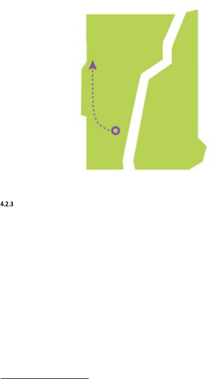
2050 Transmission Study page 35
ISO-NE PUBLIC
Figure 4-6: Northwestern Vermont Import Coolidge-Essex Roadmap
Northwestern Vermont Import Roadmap #3: New Haven-Essex and Granite-Essex Roadmap
The third roadmap would require construction of a new 345 kV line from the New Haven
substation in New Haven, Vermont, to the Essex substation just outside of the city of Burlington, in
addition to a new 230 kV overhead line from the Granite substation east of Williamstown, Vermont,
to the Essex substation.
16
Both of these new lines would require their own new substation
equipment at the Essex substation to operate at 345 kV and 230 kV, since the Essex substation is
currently only capable of 115 kV operation. This new equipment would include a new 345/115 kV
transformer and a new 230/115 kV transformer. The length of the line from New Haven to Essex
would be approximately 25 miles and the length of the line from Granite to Essex would be
approximately 45 miles. This option would require approximately 79 miles of 115 kV overhead line
rebuilds to reliably serve a 51 GW load and approximately 121 miles of 115 kV overhead line
rebuilds to reliably serve a 57 GW load. In addition to new transformers at Essex, two new 345/115
kV transformers would need to be installed at existing 345 kV substations to reach a 51 GW load
and an additional one 345/115 kV transformer would be needed at an existing 345 kV substation to
reach 57 GW. Figure 4-7 represents the general direction of power flows and location of new
transmission lines in this roadmap.
16
It may be prudent to build this line to 345 kV standards in advance, to allow for an eventual conversion of the Vermont and
New Hampshire 230 kV systems to 345 kV if necessary.

2050 Transmission Study page 36
ISO-NE PUBLIC
Figure 4-7: Northwestern Vermont Import New Haven-Essex and Granite-Essex Roadmap
Northwestern Vermont Import Roadmap #4: Minimization of New Lines Roadmap
A variation on the first roadmap was also examined to determine if the Vermont high-likelihood
concerns could be resolved without constructing entirely new overhead lines. Results showed that
the new line in parallel to the K-43 line could be eliminated if the 0.4 mile underground section of
the K-65 line between the North Ferrisburg substation and Charlotte substation, along with the 1.7
mile underground section of the K-65 line between the Shelburne substation and the Queen City
substation in southern Burlington, had an additional parallel cable added to each section. The PV-20
upgrade from 115 kV to 230 kV (in both New York and in Vermont), along with the new 230/115
kV transformer, would still be required. This option would require approximately 142 miles of 115
kV overhead line rebuilds to reliably serve a 51 GW load and approximately 192 miles of overhead
line rebuilds to reliably serve a 57 GW load. Three new 345/115 kV transformers would need to be
installed to reach 51 GW of load, and an additional two 345/115 kV transformers would be needed
to reach 57 GW. The choice between the first roadmap and this variation is therefore a choice
between building a 20.8 mile overhead line versus doubling up 2.1 miles of underground cables
plus rebuilding approximately 41 miles of overhead lines to reliably serve a 57 GW load. However,
this approach of minimizing new overhead construction is generally less robust than roadmaps
involving additional overhead transmission lines. In addition to the voltage and stability benefits of
new transmission lines, new overhead lines also provide more margin for loads higher than those
assumed in this study, different load distributions among the substations in Vermont, and other
unexpected developments. Rebuilds alone leave very little headroom to operate the system reliably,
with many lines loaded very close to their ratings under post-contingency conditions. Figure 4-8
represents the general direction of power flow and location of new transmission lines and the 115-
to-230-kV conversion in this roadmap.

2050 Transmission Study page 37
ISO-NE PUBLIC
Figure 4-8: Northwestern Vermont Import Minimization of New Lines Roadmap
4.3 Southwest Connecticut Import
Like Boston, the Southwest Connecticut area is a densely populated urban area with high demand
for power and little space for overhead transmission line corridors. As heating and transportation
are electrified between now and 2050, load in this area is anticipated to grow, and additional
transmission capacity will be necessary to serve this load reliably. While it may be possible to serve
this load by interconnecting generating and storage resources locally, the Energy Pathways study
specified relatively low amounts of offshore wind and storage for the state of Connecticut, and there
is little land available for utility-scale solar in this area. The 2050 Transmission Study assumed that
a new offshore wind farm would connect to the Norwalk substation, and that battery storage
facilities would interconnect at Cos Cob (in Greenwich, CT) and Glenbrook (in Stamford, CT). Even
with the assumption that these facilities will inject power into the subregion, additional
transmission is needed to serve load reliably.
This study found that one set of solutions could address reliability concerns in Southwest
Connecticut at a relatively lower cost and impact than other solution alternatives—hence the lack
of multiple roadmaps for this subregion. The representative solutions suggested for this area
include three new 115 kV underground cables in the Norwalk-Stamford area: one from Norwalk to
Glenbrook (in Stamford, CT); one from Ely Avenue to Norwalk Harbor (both in Norwalk, CT); and a
third extending an existing cable from its current endpoint at South End (in Stamford, CT) to Cos
Cob. The Norwalk-Glenbrook cable would take advantage of a spare 115 kV duct bank in parallel
with two existing Norwalk-Glenbrook cables, which would reduce its cost somewhat compared to
an underground cable on a brand-new route. In addition to these upgrades, 96 miles of overhead

2050 Transmission Study page 38
ISO-NE PUBLIC
115 kV lines and 6 miles of underground 345 kV lines must be rebuilt, and two 345/115 kV
transformers must be added in order to reliably serve a 51 GW winter peak load.
Additional 345 kV capacity into Southwest Connecticut would be required to serve a 57 GW winter
peak load. Today, the region is fed by only two 345 kV paths: one from Long Mountain (in New
Milford, CT), and the other from Beseck (in Wallingford, CT). Portions of the path from Long
Mountain to Norwalk are underground, leading to lower ratings than a typical 345 kV overhead
line. While additional 345 kV overhead lines would provide the capacity needed, these lines would
be lengthy and would be difficult to route and site through the densely populated areas of
Southwest Connecticut. Instead, this study suggests re-using an unused underground segment of
the Long Mountain-Norwalk path, which would allow for more power flow. This cable was
originally de-energized due to temporary over-voltage concerns.
17
Additional study would be
required to ensure that the cable could be re-energized safely without risking equipment damage;
additional substation equipment may be necessary to manage voltage if this cable is placed into
service. The costs of this study work and substation equipment would likely be far less than
developing a third 345 kV path into Southwest Connecticut. Along with re-energizing this cable, an
additional two 345/115 kV transformers, 125 miles of rebuilt overhead 115 kV lines, and 21 miles
of rebuilt overhead 345 kV lines would be necessary to reliably serve Southwest Connecticut at the
57 GW winter peak load level. Figure 4-9 represents the general direction of power flows and
location of major new transmission lines in this roadmap.
Figure 4-9: Southwest Connecticut Import Transmission Additions
4.4 Transformer Additions
As described in section 2.5, transformer capacity has the potential to create bottlenecks in the
power system between today and 2050. A large number of existing PTF transformers, primarily
345/115 kV transformers, were identified as overloaded before representative transmission
upgrades were added to the system models. Table 4-1 lists the number of transformer overloads
across different snapshots, and illustrates the correlation between transformer overloads and
increasing load. The results marked “pre-optimization” show results from July 2022, before the
study was redesigned to optimize generator interconnection locations. As described in section 2.4,
generator locations have a major impact on power flows and overloads on transformers. Results
17
Temporary over-voltage is a phenomenon caused by short-circuit conditions and by switching of transmission elements. This
phenomena is particularly severe in areas with significant development of underground transmission, including Southwest
Connecticut.
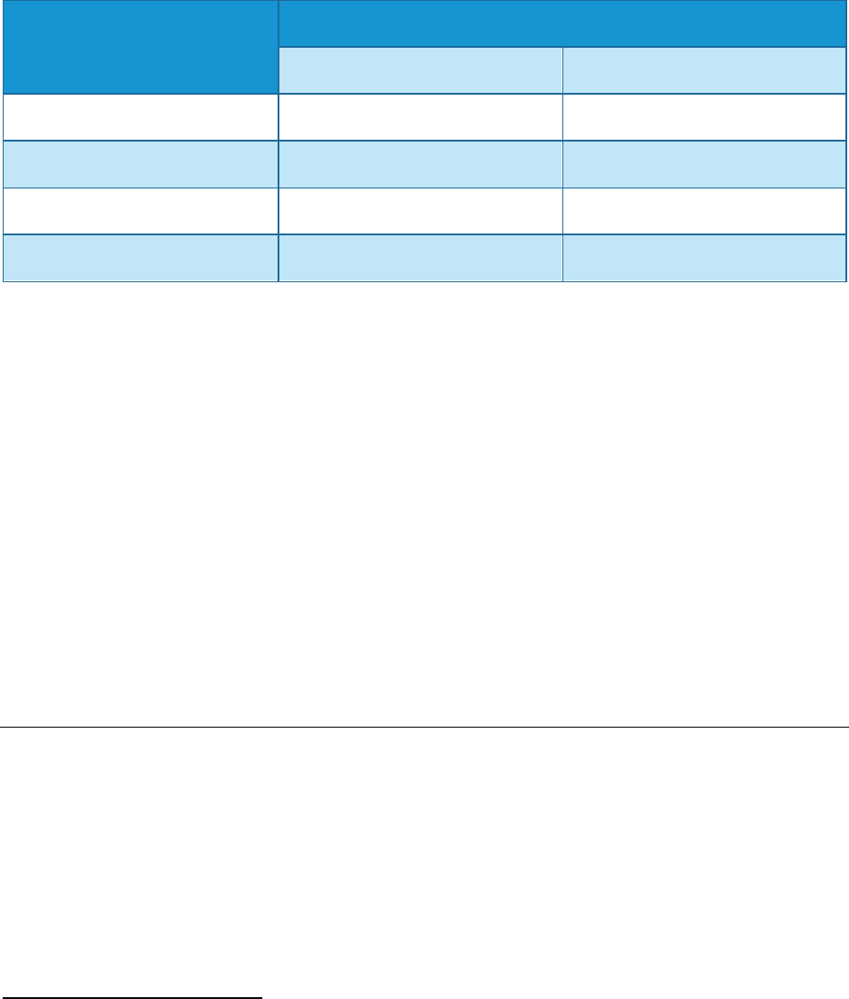
2050 Transmission Study page 39
ISO-NE PUBLIC
marked “post-optimization” show the effects of optimization on reducing transmission overloads.
All results in this table are exclusive of any representative transmission upgrades.
Table 4-1: Transformer Overloads by Snapshot Year, Pre- and Post-Optimization
Year Studied
Number of PTF Transformers Overloaded
18
Pre-Optimization Results Post-Optimization Results
2035 (35 GW Winter Peak)
14
16
2040 (43 GW Winter Peak)
56
43
2050 (51 GW Winter Peak)
86
57
2050 (57 GW Winter Peak)
99
81
While a large number of PTF transformers were overloaded in the initial study results, a smaller
number of transformers would be required to address these concerns. In many cases, multiple
existing transformers at a single substation are overloaded, and the addition of a single new
transformer is sufficient to return the loading on all existing transformers to applicable limits.
While the exact number of required transformers varies based on the roadmap chosen for North-
South/Boston Import and Northwest Vermont, all combinations of roadmaps require
approximately 40 new transformers to address all reliability concerns. Of these 40 transformers,
approximately 20 would address high-likelihood concerns. The remaining 20 would be needed to
address non-high-likelihood concerns, and in many instances, are only needed to serve load in the
57 GW winter peak snapshot.
Given the long lead times (18-24 months), limited manufacturing capability, and transportation
challenges for large power transformers, transformer capacity has the potential to be a significant
limiting factor on the evolution of the power system and the electrification of end-user energy
consumption.
4.5 Other High-Likelihood Concerns
In addition to the concerns described above, the study revealed a number of other isolated high-
likelihood concerns that were not related to consistent trends like those associated with North-
South transfers or other named high-likelihood concerns. The following upgrades were considered
in order to address these other high-likelihood concerns:
• Upgrade and convert 298 miles of 69 kV lines to 115 kV.
• Rebuild 225 miles of overhead 115 kV lines.
• Rebuild 37 miles of overhead 345 kV lines.
• Build 13 miles of new overhead 115 kV lines.
18
Numbers in this table are based on N-1-1 results when accounting for single-element second contingencies (loss of line,
transformer, etc.) but not multiple-element second contingencies (breaker failures, double-circuit tower contingencies, etc.).

2050 Transmission Study page 40
ISO-NE PUBLIC
• Build two new overhead 345 kV lines between Brayton Point and Grand Army (both in
Somerset, MA), for a total of 3 miles of new construction.
• Increase the rating of the series capacitor on line 3023 in Orrington, ME.
These upgrades are scattered around New England, rather than concentrated in a particular area.
Full details on these additional upgrades can be found in the Technical Appendix to this report.
4.6 Non-High-Likelihood Concerns
Finally, many concerns found in this study were not considered high-likelihood concerns, and are
mainly related to serving load for the 57 GW winter peak load level. Since they only appear at this
load level, they are particularly sensitive to the distribution of load among individual substations. If
the evolution of the region’s distribution system differs significantly from the assumptions studied,
it is possible that new distribution substations will be located in a way that changes the severity
and location of these reliability concerns. Therefore, these concerns are not considered high-
likelihood.
The upgrades associated with these non-high-likelihood concerns are as follows. While the exact
upgrades may vary depending on the location of distribution load-serving substations, this list of
upgrades is a reasonable approximation of upgrades that will be required if the region’s load grows
to a 57 GW winter peak.
• Rebuild 393 miles of overhead 115 kV transmission lines.
• Rebuild 287 miles of overhead 345 kV transmission lines.
• Build 105 miles of new overhead 115 kV transmission lines.
• Build 57 miles of new underground 115 kV cables.
• Replace 10 miles of existing underground 115 kV cables with higher-rated cross-linked
polyethylene (XLPE) cables.
• Install 4 new series reactors at various locations throughout New England.
• Install approximately 300 new circuit breakers at various substations throughout New
England.
• Separate transmission lines on 10 sections of double-circuit towers.
19
19
Double-circuit towers are structures supporting two overhead transmission lines on the same structure. NERC, NPCC, and
ISO-NE reliability criteria require the consideration of the loss of both lines on double-circuit towers simultaneously, which is
often caused by lightning strikes. Separation of circuits on double-circuit towers involves building new structures for at least
one of the two circuits, and depending on the right-of-way layout, may or may not require additional right-of-way width.

2050 Transmission Study page 41
ISO-NE PUBLIC
4.7 Maps of All Transmission Upgrades and Additions
The maps in this section show the full set of transmission upgrades identified as conceptual
roadmaps in this study. Rebuilds of existing transmission lines are shown in purple and new
transmission lines are shown in red.
The maps below should not be considered authoritative lists of all line rebuilds; due to the scale of
the maps and approximations of substation locations, some lines are difficult or impossible to
distinguish from each other. All transmission lines are represented as straight lines between
endpoints, and thus do not reflect actual line routes or locations of rights-of-way. This study
examined four different northwestern Vermont roadmaps and four different North – South/Boston
Import roadmaps. The northwestern Vermont roadmaps were far enough away from the North –
South/Boston Import roadmaps that they can be considered to be independent from each other.
The maps below show one northwestern Vermont roadmap paired with one North – South/Boston
Import roadmap each, but these could be paired in any combination, rather than being limited to
the ones shown below. A full list of rebuilt transmission lines for each roadmap may be found in the
Technical Appendix to this report.

2050 Transmission Study page 42
ISO-NE PUBLIC
Figure 4-10: Transmission Upgrades and Additions for the Coolidge -Essex Roadmap and the AC Roadmap
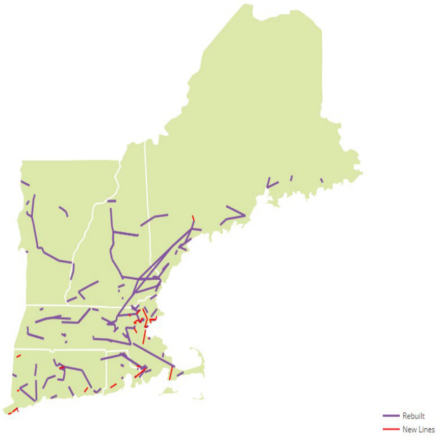
2050 Transmission Study page 43
ISO-NE PUBLIC
Figure 4-11: Transmission Upgrades and Additions for the Minimization of New Lines Roadmaps

2050 Transmission Study page 44
ISO-NE PUBLIC
Figure 4-12: Transmission Upgrades and Additions for the PV-20 Roadmap and the DC Roadmap

2050 Transmission Study page 45
ISO-NE PUBLIC
Figure 4-13: Transmission Upgrades and Additions for the New Haven - Essex Roadmap and the Offshore Grid
Roadmap

2050 Transmission Study page 46
ISO-NE PUBLIC
Section 5: Cost of Transmission System Upgrades
One of the major goals of the 2050 Transmission Study was to provide a rough estimate of the costs
required to develop the transmission system of 2050. The projects proposed as conceptual
roadmaps in this study are not intended to constitute a transmission plan, and the region’s
transmission system will likely develop differently from the system envisioned in this study.
However, the identified upgrades are still useful for providing an order-of-magnitude estimate of
future transmission system costs. These estimated costs are intended to inform consumers,
industry stakeholders, and policy makers of the costs inherent in maintaining reliable transmission
service through the clean energy transition.
The ISO’s estimates of costs for these representative transmission projects were developed from
two sources. The first, used for more complex projects, was Electrical Consultants, Inc. (ECI), a
consultant with extensive experience in project management and transmission system
construction. ECI’s cost estimates were primarily made up of materials, labor, and right-of-way
costs. These cost estimates did not include some aspects of transmission costs, such as financing
costs (allowance for funds used during construction, or AFUDC), contingency costs for unexpected
difficulties during construction, and engineering, permitting, and indirect costs. ECI did include
permitting fees and filing costs, but these costs did not reflect the extensive labor typical of
permitting large projects in New England. To account for these and to ensure ECI’s calculated costs
were easily comparable to actual project costs in New England, a 95% adder was applied. This
adder was calculated as follows:
• 10% adder for financing costs: Recent transmission projects in New England have incurred
financing costs in the range of 5-14% of the total labor, materials, and right-of-way costs. A
10% adder approximates the midpoint of this range.
• 20% adder for engineering, permitting, and indirect costs: These costs have varied widely
on recent transmission projects, from 2% to 32% of the total labor, materials, and right-of-
way costs. Larger projects, especially those involving underground transmission, tend to be
near the higher end of this range. A 20% adder is slightly higher than the midpoint of this
range.
• 50% adder for contingency: ISO-NE Planning Procedure 4 (PP4), Attachment D specifies a
contingency adder of 30-50% for projects with cost estimates in the “Proposed” stage of
project development.
20
ECI’s estimates were “desktop” estimates made without field visits
or detailed analysis of local site conditions. Consequently, the high end of this 30-50% range
is appropriate to reflect the possibility of significant extra costs as projects proceed.
• The 50% contingency is applied to the material/labor/right-of-way cost, financing, and
engineering/permitting/indirect costs; this leads to a final cost of 130% (the financing and
engineering/permitting/indirect adder) times 150% (the contingency adder), or a total of
195% (95% above the original materials/labor/right-of-way cost).
The second source of cost data was a set of assumptions based on recently-observed project costs
in New England. The ISO analyzed cost data from reliability projects in both the
Regional System
Plan (RSP) Project List and asset condition projects from the Asset Condition List (ACL). These
projects were used to develop per-mile assumptions for new or substantially rebuilt transmission
lines, and for additions to existing substations such as new transformers and circuit breakers.
20
PP4 Attachment D is available on ISO-NE’s website at https://www.iso-ne.com/static-
assets/documents/rules_proceds/isone_plan/pp04_0/pp4_0_attachment_d.pdf.

2050 Transmission Study page 47
ISO-NE PUBLIC
These cost assumptions were used for rebuilds of existing lines and other less complex projects.
Because of the sheer number of transmission projects included in this study, this approach
provided a more cost-effective method for estimating costs. Conducting detailed cost analysis for
these transmission line rebuilds and other simpler projects would be expensive, time-consuming,
and unlikely to add significant precision. Some projects will likely exceed the costs calculated using
these assumptions, and other projects will be less expensive than the assumptions, but the ISO’s
expectation is that the aggregated cost of the full list of these projects will be within an order-of-
magnitude range of accuracy. The cost assumptions developed are shown in Table 5-1.
Table 5-1: Cost Assumptions for 2050 Transmission Study Upgrades
Project Type
Assumed Cost
69/115 kV – rebuild of existing overhead
lines
$5M per mile
69/115 kV – new overhead line
construction
$7M per mile
230/345 kV – rebuild of existing overhead
lines
$6M per mile
230/345 kV – new overhead line
construction
$8M per mile
New 115/69 kV transformer
$10M per transformer
New 345/115 kV transformer
$10M per transformer
New 69/115 kV circuit breaker
$2M per breaker
New 230/345 kV circuit breaker
$2M per breaker
New/replaced underground line
construction (any voltage level)
$35M per mile
In addition to the costs listed above, this study uses representative cost assumptions for
components of offshore grids. These costs were developed as part of the National Renewable
Energy Laboratory (NREL)’s Atlantic Offshore Wind Transmission Study, and presented as part of a
progress update on that study on July 27, 2023. These costs are illustrated in Table 5-2.

2050 Transmission Study page 48
ISO-NE PUBLIC
Table 5-2: Cost Assumptions for Offshore Grid Components
Component
Assumed Cost
HVDC Circuit Breaker
$37.5M per breaker
“End” platform (wind farm connection to one other wind farm)
$112.5M per
platform
“Middle” platform (wind farm connection to two other wind farms)
$142.5M per
platform
HVDC Cable
$10.5M per mile
The costs provided by the NREL team include engineering, permitting, indirect, and financing costs;
however, they do not include any allowance for contingency. As a result, a 50% adder above the
materials and labor costs were applied to these estimates. This 50% adder is included in the costs.
A number of caveats must be applied to the cost estimates included in this report. First, they
include only a subset of the total costs of transitioning the electric delivery system to a low-
emissions future. The costs of upgrades related to voltage performance, transient stability
performance, short-circuit performance, and other aspects of transmission planning that are
beyond the scope of this study are not included here. Other transmission upgrades, such as new
load-serving substations and required generator interconnection upgrades, are also not included.
Second, significant upgrades to distribution systems will be needed in order to accommodate a
2050 peak load that is roughly double what New England has historically experienced. These
distribution system upgrades will form a substantial portion of the cost of the clean energy
transition. However, this is beyond the scope of the 2050 Transmission Study, and beyond the ISO’s
jurisdiction and expertise.
It should also be noted that all costs quoted in this report are expressed in present-day (2023)
dollars. No adjustments to account for inflation, increases in equipment prices, or other long-term
trends were applied. As New England and other regions of the United States and the world are
undergoing energy transitions simultaneously, it is difficult to predict long-term trends in electrical
equipment costs, and these long-term trends could significantly affect the costs quoted in this
report.
5.1 Estimated Costs by Roadmap and Year
The following section lays out the total costs estimated by the 2050 Transmission Study, and
categorizes those costs by type of rebuild. All costs are subject to the caveats noted previously.
Costs are provided for each roadmap and are broken down by the year studied (2035, 2040, and
2050) to illustrate the degree to which costs might possibly be deferred to later dates in the energy
transition. Two sets of costs are included for 2050: one to accommodate a winter peak of 51 GW (a
reduced peak load, as described in Section 2.1), and one to accommodate the 57 GW peak load
assumed in the Energy Pathways to Deep Decarbonization report.
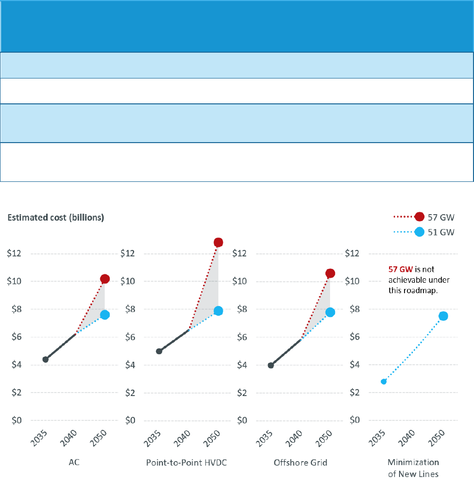
2050 Transmission Study page 49
ISO-NE PUBLIC
Costs illustrated in Table 5-3 and Figure 5-1 are associated with the North-South/Boston Import
roadmaps. These costs will be affected by the choice of four roadmaps detailed in Section 4.1.
Figure 5-2 and Figure 5-3 categorize the costs by rebuild type for both the 51 GW and 57 GW winter
peak load snapshots.
Table 5-3: Estimated Cumulative Costs for North-South/Boston Import Roadmaps
Year/Load Level
AC Roadmap
Minimization of
New Lines
Roadmap
Point-to-Point
HVDC Roadmap
Offshore Grid
Roadmap
2035
$4.4 Billion
$2.8 Billion
$5.0 Billion
$4.0 Billion
2040
$6.2 Billion
$5.0 Billion
$6.5 Billion
$5.8 Billion
2050 (51 GW
winter peak)
$7.6 Billion
$7.5 Billion
$7.9 Billion
$7.9 Billion
2050 (57 GW
winter peak)
$10.2 Billion
Not Achievable*
$12.8 Billion
$10.7 Billion
*As described previously, the Minimization of New Lines roadmap is not capable of reliably serving a 57 GW peak load.
Figure 5-1: Estimated Cumulative Costs for North-South/Boston Import Roadmaps

2050 Transmission Study page 50
ISO-NE PUBLIC
Figure 5-2: Cost Categories for North-South/Boston Import Roadmaps: 51 GW Winter Peak
Figure 5-3: Cost Categories for North-South/Boston Import Roadmaps: 57 GW Winter Peak
$2.27
$4.85
$4.72
$4.13
$2.39
$0.84
$0.86
$0.86
$2.79
$2.22
$2.30
$2.51
$7.45 B
$7.91 B
$7.88 B
$7.50 B
$0 $2 $4 $6 $8 $10 $12 $14
Minimize New Lines
Offshore Grid
DC
AC
New Transmission 345 kV Line Rebuilds 115 kV Line Rebuilds
Estimated cost at 51 GW (billions)
$5.32
$7.37
$4.61
$2.02
$2.27
$2.13
$3.32
$3.14
$3.41
Not achievable for a 57 GW peak.
$10.66 B
$12.78 B
$10.15 B
$0 $2 $4 $6 $8 $10 $12 $14
Minimize New Lines
Offshore Grid
DC
AC
New Transmission 345 kV Line Rebuilds 115 kV Line Rebuilds
Estimated cost at 57 GW (billions)

2050 Transmission Study page 51
ISO-NE PUBLIC
Costs illustrated in Table 5-4 and Figure 5-4 are associated with the Northwest Vermont roadmaps.
As with North-South/Boston Import costs above, multiple roadmaps were developed for this high-
likelihood concern and detailed in Section 4.2. Figure 5-5 and Figure 5-6 categorize the costs by
rebuild type for both the 51 GW and 57 GW winter peak load snapshots.
Table 5-4: Estimated Cumulative Costs for Northwestern Vermont Import Roadmaps
Year/Load Level
PV-20 Upgrade
and Doubling of
K-43 Roadmap
Coolidge – Essex
Roadmap
New Haven –
Essex and
Granite – Essex
Roadmap
Minimization of
New Lines
Roadmap
2035
$0.7 Billion
$1.1 Billion
$1.1 Billion
$0.6 Billion
2040
$0.8 Billion
$1.3 Billion
$1.1 Billion
$0.8 Billion
2050 (51 GW
winter peak)
$0.9 Billion
$1.5 Billion
$1.2 Billion
$0.9 Billion
2050 (57 GW
winter peak)
$1.2 Billion
$2.0 Billion
$1.4 Billion
$1.2 Billion
Figure 5-4: Estimated Cumulative Costs for Northwestern Vermont Import Roadmaps

2050 Transmission Study page 52
ISO-NE PUBLIC
Figure 5-5: Cost Categories for NWVT Import Roadmaps: 51 GW Winter Peak
Figure 5-6: Cost Categories for NWVT Import Roadmaps: 57 GW Winter Peak
$0.17
$0.81
$1.00
$0.27
$0.71
$0.39
$0.53
$0.60
$0.88 B
$1.20 B
$1.53 B
$0.87 B
$0.0 $0.5 $1.0 $1.5 $2.0
Minimize New Lines
New Haven-Essex
Coolidge-Essex
PV-20
New Transmission 115 kV Line Rebuilds
Estimated cost at 51 GW (billions)
$0.19
$0.82
$1.01
$0.29
$0.96
$0.60
$0.95
$0.95
$1.15 B
$1.42 B
$1.96 B
$1.24 B
$0.0 $0.5 $1.0 $1.5 $2.0
Minimize New Lines
New Haven-Essex
Coolidge-Essex
PV-20
New Transmission 115 kV Line Rebuilds
Estimated cost at 57 GW (billions)
2050 Transmission Study page 53
ISO-NE PUBLIC
Costs illustrated in Table 5-5 are associated with the Southwest Connecticut Import high-likelihood
concern.
Table 5-5: Estimated Cumulative Costs for Southwest Connecticut Import
Year/Load Level
Southwest Connecticut Import
2035
$0.5 Billion
2040
$0.7 Billion
2050 (51 GW
winter peak)
$0.8 Billion
2050 (57 GW
winter peak)
$1.6 Billion
Costs illustrated in Table 5-6 are associated with miscellaneous high-likelihood concerns.
Table 5-6: Estimated Cumulative Costs for Miscellaneous High-Likelihood Concerns
Year/Load Level
Miscellaneous High-Likelihood Concerns
2035
$1.7 Billion
2040
$2.8 Billion
2050 (51 GW
winter peak)
$3.1 Billion
2050 (57 GW
winter peak)
$3.1 Billion
Table 5-7 shows the costs associated with addressing non-high-likelihood concerns:

2050 Transmission Study page 54
ISO-NE PUBLIC
Table 5-7: Estimated Cumulative Costs for Non-High-Likelihood Concerns
Year/Load Level
Non-High-Likelihood Concerns
2035
$0.4 Billion
2040
$1.4 Billion
2050 (51 GW
winter peak)
$3.2 Billion
2050 (57 GW
winter peak)
$6.6 Billion
Table 5-8 totals the costs associated with each year in the tables above and provides a range of
costs for each year studied, while Figure 5-7 illustrates how those costs change by year studied and
maximum load served.

2050 Transmission Study page 55
ISO-NE PUBLIC
Table 5-8: Estimated Cumulative Costs by Year Studied
Year/Load
Level
Maximum Load
Served (MW)
Total Cost Range Cost Breakdown
2035 35,000 $6-9 Billion
$2.8-5.0 Billion N-S/Boston
$0.6-1.1 Billion NWVT
$0.5 Billion SWCT
$1.7 Billion Misc. HLC
$0.4 Billion Non-HLC
2040 43,000 $11-13 Billion
$5.0-6.5 Billion N-S/Boston
$0.8-1.3 Billion NWVT
$0.7 Billion SWCT
$2.8 Billion Misc. HLC
$1.4 Billion Non-HLC
2050 (51 GW
winter peak)
51,000 $16-17 Billion
$7.5-7.9 Billion N-S/Boston
$0.9-1.5 Billion NWVT
$0.8 Billion SWCT
$3.1 Billion Misc. HLC
$3.2 Billion Non-HLC
2050 (57 GW
winter peak)
57,000 $23-26 Billion
$10.2-12.8 Billion N-S/Boston
$1.2-2.0 Billion NWVT
$1.6 Billion SWCT
$3.1 Billion Misc. HLC
$6.6 Billion Non-HLC

2050 Transmission Study page 56
ISO-NE PUBLIC
Figure 5-7: Total Costs by Year Studied
Note that these costs are only part of the required total investment in the transmission system.
Other costs include asset condition projects unrelated to this study, and costs required to meet
voltage, stability, and short-circuit needs. While these costs appear to be quite large, they should be
viewed in the context of typical transmission system expenditures in New England on a yearly
basis. The spending on these projects will be spread out over a 26-year period between now and
2050, so the total cost of $16-$17 billion to serve a 51 GW winter peak load is approximately $0.62-
$0.65 billion per year. Similarly, the total cost of $23-$26 billion to serve a 57 GW winter peak load
results in average spending of approximately $0.88-$1.00 billion per year. By way of comparison,
total transmission project spending between 2002 and 2023 on both reliability-based projects and
asset condition projects totaled $15.3 billion, or an average of approximately $0.73 billion per year.
Similarly, the forecasted combined spending on reliability and asset condition projects in the
upcoming five-year period, from December 2023 through December 2028, is a total of
approximately $3.85 billion, or an average of $0.77 billion per year.
21
Many of the line rebuilds
proposed in this study will also overlap with asset condition needs, and any one project could
address both system expansion and aging equipment.
21
Source: RSP Project List and Asset Condition List June 2023 Update, https://www.iso-ne.com/static-
assets/documents/2023/06/final_project_list_presentation_june_2023.pdf
$0 B
$5 B
$10 B
$15 B
$20 B
$25 B
Range for 51 GW
peak in 2050
Estimated cost (billions)
Range for 57 GW
peak in 2050
43 GW
2040
35 GW
2035
Low estimate
High estimate
2050 Transmission Study page 57
ISO-NE PUBLIC
Section 6: Future Work
The 2050 Transmission Study is the first longer-term transmission study conducted for New
England. Results revealed many important lessons about the future development of New England’s
transmission system, and many opportunities for similar studies in the future. As time passes, the
assumptions regarding generator types, sizes, and locations used in this study will be replaced with
real-life data, providing more precision around the transmission system upgrades that will be
required in the future.
One potential area of focus for future longer-term transmission studies is the addition of analysis
beyond steady-state thermal analysis. As mentioned in Section 1.1.4, the scope of this study was
limited to steady-state thermal analysis, due in part to uncertainties about the detailed
characteristics of future generators. More detailed models of future generation projects will allow
future studies to include analysis of transmission system voltage, which will shed light on certain
substation upgrades that may be required to maintain acceptable voltage and avoid equipment
damage. In addition, these models may permit the ISO to analyze transient stability and
electromagnetic transient (EMT) performance. These types of analyses examine the performance of
the system in the milliseconds to seconds following an unexpected event like a lightning strike or
tree contact on a transmission line, ensuring that generators can continue supplying power through
the event and that the system can recover to a new operating condition. Finally, future longer-term
transmission studies may leverage the findings of the ISO’s economic studies to examine conditions
other than summer and winter peak loads. Analysis from economic studies will predict likely
system conditions for off-peak periods (including load levels, renewable energy output, and the
types of generators likely to be operating in a given hour), and can highlight periods of particular
stress on the transmission system. This data can then be used in a future longer-term transmission
study to examine the transmission system’s performance during these periods of interest.
At the time of this report’s publication, the longer-term transmission study process is purely
informational. However, the ISO began stakeholder discussions on Phase II of the longer-term
transmission study process in October 2023. This second phase is designed to create a process in
the ISO New England Open Access Transmission Tariff by which NESCOE can choose transmission
system concerns to address, conduct a Request for Proposals to solicit transmission project
proposals, and then advance those proposals towards construction and operation. Depending on
the timing of these changes to the Tariff, the results of this study or other future longer-term
transmission studies may inform this solution development process.
Another key topic related to the future of the New England power system is the expansion of the
distribution system. Plans for the distribution system are outside the ISO’s jurisdiction and area of
expertise but could be a key input for further transmission studies. With more granular data on
plans to meet customer load, future longer-term transmission studies can include better data on the
location and sizes of substations that transfer electricity from the transmission system to local
distribution systems, and eventually to individual customers. This will allow for more precise
modeling of the future transmission system and a more accurate view of the region’s future power
system.
2050 Transmission Study page 58
ISO-NE PUBLIC
Section 7: Conclusion
As the clean energy transition accelerates, power flows across New England’s transmission system
will eclipse all previous highs. The “best case” 51 GW winter peak load snapshot analyzed in this
study is more than double the highest winter peak ever recorded in New England, January 2004’s
23GW level, and the “worst case” 57 GW winter peak load snapshot is almost 150% higher.
Assuming increased build-outs of renewables continue, and electrification of heating and
transportation proceeds as expected, the region’s aging transmission system has the potential to
become a significant bottleneck to progress if it does not keep pace with changes to other elements
of the power system.
In 2021, NESCOE and the ISO recognized that the traditional 10-year planning horizon was no
longer sufficient to adequately analyze a transmission system undergoing such immense change.
The 2050 Transmission Study is an unprecedented look at the future of New England’s
transmission system, and the results produced by this study will assist stakeholders and the ISO in
making important decisions about improvements and pathways forward. Processes developed and
lessons learned in this study also pave the way for future studies, as the ISO continues to meet its
commitment to overseeing a reliable and cost-effective regional transmission system. With the
addition of the Longer-Term Transmission Planning process to the ISO New England Open Access
Transmission Tariff, studies like this one will be conducted periodically to re-assess the long-term
evolution of the transmission system and associated costs.
Although the roadmaps provided in this study are not intended as comprehensive plans, and
overloads and issues associated with the high-likelihood concerns may not occur in exactly the way
this study has outlined, these big-picture observations represent a large step towards meeting the
challenges that lie ahead for New England’s transmission system. Ensuring the reliable, economic
delivery of electricity that customers have come to expect will require innovative solutions, and
most importantly, collaboration and communication between stakeholders, the states, transmission
owners, and the ISO.
Targeted approaches to problem-solving, like optimizing generator locations or right-sizing asset
condition projects, could become particularly crucial as the region moves towards upgrading an
aging system in the most cost-effective manner. Such targeted problem-solving requires
cooperation and collaboration. The ISO will continue to provide the forward-looking analysis
presented in this study in future studies, and will continue to focus on longer-term transmission
planning studies in collaboration with stakeholders to help identify the best paths forward.
