42
Vol.
40
No.
1 2007
February
1
. Introductio
n
IHI has recentl
y
entered the APM
(
Automated People
Mover
)
mar
k
et as we expect g
l
o
b
a
l
d
eman
d
to
i
ncrease.
The APM s
y
stem is
g
rowin
g
in popularit
y
, especiall
y
fo
r
p
assenger transportat
i
on w
i
t
hi
n a
i
rports, an
d
t
h
ere are many
new applications bein
g
planned, mainl
y
in North America.
Our company w
ill
meet t
h
e
i
ncreas
i
ng nee
d
s
b
y means o
f
o
ur ori
g
inal rubber tire t
y
pe vehicle technolo
gy
and s
y
stem
integration technique in cooperation with Niigata Transys
Co., Lt
d
.
(h
ere
i
na
f
ter ca
ll
e
d
NTS
)
. P
h
ase 1 o
f
t
h
e new APM
s
y
stem construction for Hon
g
Kon
g
International Airport,
o
ur
fi
rst or
d
er rece
i
ve
d
, was comp
l
ete
d
i
n Decem
b
er 2006.
In this paper, we introduce the APM s
y
stem for Hon
g
Kon
g
Internat
i
ona
l
A
i
rport an
d
i
ts tec
h
no
l
ogy.
2
.
O
utl
i
n
e
I
n Decem
b
er 2005
,
we
d
e
li
vere
d
new 3 4-car ve
hi
c
l
es
(
F
i
g
.
2
)
to add to the existin
g
APM s
y
stem in the
P
assenger Term
i
na
l
Bu
ildi
ng
(h
ere
i
na
f
ter ca
ll
e
d
ex
i
st
i
n
g
PTB
li
ne
)
o
f
Hon
g
Kon
g
Internat
i
ona
l
A
i
rport
(
F
i
g
.
1
)
. Construction Phase 1 of the new Sk
y
Plaza
APM s
y
stem
(h
ere
i
na
f
ter ca
ll
e
d
SKP
li
ne
)
connect
i
n
g
the nei
g
hborin
g
Sk
y
Plaza and Terminal Buildin
g
1
h
as
b
een comp
l
ete
d
recent
l
y. T
hi
s cons
i
sts o
f
a
2
-station route of about 550 m and a maintenance area,
w
i
t
h
a
ll
t
h
e
f
ac
ili
t
i
es
i
nsta
ll
e
d
un
d
ergroun
d
. Un
d
er
Construction Phase 2, scheduled for sprin
g
2008, the
s
erv
i
ce w
ill
b
e exten
d
e
d
to t
h
e
f
erry term
i
na
l
S
k
yP
i
er,
which connects Hon
g
Kon
g
International Airport
with various
p
laces in mainland China and Macau.
T
h
e
l
engt
h
o
f
t
h
e route a
f
ter t
h
e extens
i
on
h
as
b
een
completed will total 1 200 m
(
Fi
g
.
3
).
F
irst
T
ransportation
P
rojec
t
APM S
y
stem
f
or Hon
g
Kon
g
Internationa
l
Airpor
t
S
EKIYA Takao
:
T
ransportation S
y
stem Department,
Lo
g
istics S
y
stems Division, Lo
g
istics S
y
stems
&
S
tructure
s
O
DA Yosh
i
o : C
hi
e
f
Eng
i
neer, Transportat
i
on System D
i
v
i
s
i
on,
Nii
g
ata Trans
y
s Co., Ltd.
F
i
g
. 1 Com
p
lete View o
f
Hon
g
Kon
g
International Air
p
or
t
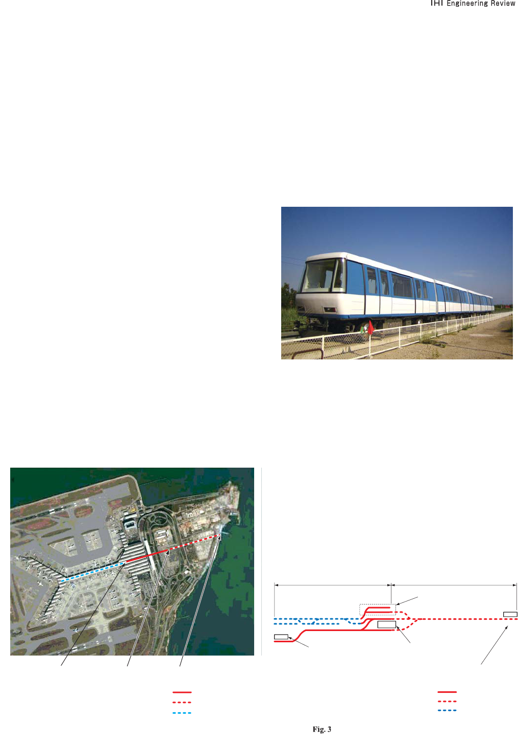
Fig. 2
N
ew APM Vehicle for Hon
g
Kon
g
International Air
p
ort
Terminal Building 2
“SkyPlaza”
Terminal Building 1
“East Hall”
Ferry Terminal
“SkyPier”
: SKP Line (Phase 1)
: SKP Line (Phase 2)
: Existing PTB line
(Note)
From Google Earth
Terminal Building 1
“East Hall”
Terminal Building 2
“SkyPlaza”
Maintenance area
Ferry terminal
“SkyPier”
: SKP line (Phase 1)
: SKP line (Phase 2)
: Existing PTB line
(Note)
About 550 About 650
A
pproximate Route Diagram (Unit : m
)

4
3
Vol.
40
No.
1 2007
February
3.
S
kyPlaza APM
S
yste
m
Th
e range o
f
t
hi
s construct
i
on wor
k
covers re
i
n
f
orce
d
c
oncrete track
(
excludin
g
the APM vehicle
)
, steel
g
uide
ra
il
, ma
i
ntenance area an
d
power
di
str
ib
ut
i
on system,
power rail, communication s
y
stem and ATC
(
Automatic
T
ra
i
n Contro
l)
. Here
f
o
ll
ows a
d
escr
i
pt
i
on o
f
t
h
e ATC, a
v
itall
y
important part of the APM s
y
stem.
T
h
e ATC compr
i
ses ATP
(
Automat
i
c Tra
i
n Protect
i
on
)
to
s
upport sa
f
e operat
i
on; ATO
(
Automat
i
c Tra
i
n Operat
i
on
)
t
o control automatic operation, includin
g
door openin
g/
cl
os
i
ng an
d
ve
hi
c
l
e acce
l
erat
i
ng
/d
ece
l
erat
i
ng; an
d
ATS
(
Automatic Train Supervision
)
to command, monitor, and
recor
d
t
h
e operat
i
on. T
h
e tota
l
APM system con
fi
gurat
i
on
i
s shown below.
R
i
g
id
con
d
uctor power ra
il
Supp
l
y
i
ng power to t
h
e
APM ve
hi
c
le
Re
i
n
f
orce
d
concrete trac
k
Runn
i
ng sur
f
ace
f
or t
h
e
APM ve
hi
c
le
Guide rail and point switch Fo r
g
uidin
g
the APM
vehicle
Power distribution s
y
stem Power receivin
g
, volta
g
e
r
e
d
uct
i
on
,
an
d
di
str
ib
ut
i
on
Buffer For stoppin
g
the vehicle
ATP A
u
t
o
m
a
t
ic
Tr
ai
n
Protection
(
safet
y
device
of
t
h
e APM ve
hi
c
l
e
)
ATO Automat
i
c Tra
i
n
Operation
(
automatic
o
perat
i
on o
f
t
h
e APM
vehicle
)
AT
S
Automat
i
c Tra
i
n
Supervision
(
s
y
stem
o
perat
i
on, mon
i
tor
i
ng,
a
n
d
recor
di
n
g)
Communication system Pu blic address to the
ve
hi
c
l
e an
d
p
l
at
f
orm,
a
n
d
int
e
r
co
m
be
t
wee
n
p
assengers an
d
t
h
e
o
perator at the airport’s
op
erat
i
on contro
l
center
Maintenance area For APM vehicle stora
g
e
a
n
d
m
ai
nt
e
n
a
n
ce
Ever
y
su
b
s
y
stem
i
s con
fig
ure
d
to con
f
orm to t
h
e
d
omestic APM system. In consideration of redundancy,
a
d
ua
l
or
d
up
l
ex
h
ar
d
ware con
fi
gurat
i
on
i
s a
d
opte
d
to
s
ecure hi
g
h reliabilit
y
.
3
.1 ATP (Automatic Train Protection)
Thi
s
i
s a sa
f
ety cont
i
nuous-mon
i
tor
i
ng type
d
ev
i
ce.
A
TP can automaticall
y
limit the vehicle speed or
s
to
p
t
h
e ve
hi
c
l
e,
b
ase
d
on
i
n
f
ormat
i
on
f
rom t
h
e APM
v
ehicle ahead or route condition. This device functions
i
n
d
epen
d
ent
l
y o
f
t
h
e ATO
d
ev
i
ce
.
As an APM is unable to run on steel rails and use them
for transmittin
g
si
g
nals, it adopts a s
y
stem to receive
s
pee
d
s
i
gna
l
s transm
i
tte
d
f
rom an
i
n
d
uct
i
ve
l
oop co
il
i
nstalled in the center of the concrete track, with an
antenna installed at the head of the vehicle. As the si
g
nal
s
ystem,
i
t uses a
fi
xe
d
bl
oc
k
system t
h
at
di
v
id
es t
h
e trac
k
i
nto
fi
xe
d
bl
oc
k
s an
d
i
n
di
cates t
h
e spee
d
li
m
i
t
i
ng
f
or eac
h
b
lock dependin
g
on
q
the
p
osition of a vehicle ahead,
w
t
h
e po
i
nt sw
i
tc
h
di
rect
i
on,
e
t
he
tr
ack
e
n
d
a
n
d
r
t
he
civil constraints. These si
g
nals are used not onl
y
to limit
s
pee
d
b
ut a
l
so to
id
ent
if
y t
h
e ve
hi
c
l
e’s
di
rect
i
on an
d
t
h
e
door openin
g
/closin
g
direction interlock at a station, thus
en
h
anc
i
ng sa
f
ety
.
For Tra
i
n Detect
i
on
(
TD
)
on t
h
e trac
k
, a c
h
ec
k
-
i
n
/
c
h
ec
k
-
out system
i
s a
d
opte
d
ut
ili
z
i
ng antennas
i
nsta
ll
e
d
at t
h
e
ve
hi
c
l
e
h
ea
d
an
d
rear
.
For interlocked control of the
p
oint switches and the
si
gna
l
s, Computer Base
d
Inter
l
oc
ki
ng
(
CBI
)
i
s use
d
as
it can fl exibl
y
cope with future extension and chan
g
es in
o
p
erat
i
on.
F
i
g
ure
4
shows ATP/TD confi
g
uration.
3.2 ATO (Automatic Train Operation)
ATO compr
i
ses 3 types o
f
equ
i
pment: t
h
e on-
b
oar
d
ATO
contro
ll
er, t
h
e ATO
d
ata transm
i
ss
i
on equ
i
pment, an
d
the station ATO e
q
ui
p
ment. These have the functions
o
f
automat
i
c
d
oor open
i
ng
/
c
l
os
i
ng, automat
i
c ve
hi
c
l
e
s
tartin
g
, deceleratin
g
, and stoppin
g
on behalf of the
d
r
i
ver or atten
d
ant. T
h
ey a
l
so ma
k
e
i
t poss
ibl
e to transm
i
t
vehicle information to the operator who is monitorin
g
the
o
p
erat
i
on o
f
t
h
e APM at t
h
e a
i
r
p
ort’s o
p
erat
i
on contro
l
center, allowin
g
remote control. Here we describe the
ATO
d
ata transm
i
ss
i
on e
q
u
ip
ment an
d
t
h
e stat
i
on ATO
equ
i
pment.
The ATO data transmission equipment continuously
m
on
i
tors t
h
e ve
hi
c
l
e’s state, ma
ki
ng remote ve
hi
c
l
e
control
p
ossible. Like ATP, this is also transmitted an
d
r
ece
i
ve
d
b
y means o
f
t
h
e
i
n
d
uct
i
ve
l
oop co
il
i
nsta
ll
e
d
i
n
the center of the concrete track and the antenna installed
o
n t
he
vehicle.
T
he
o
n-
boa
r
d
ala
rm
s
a
n
d
s
t
a
t
es
collec
t
ed
by
the ATO data transmission equipment are displa
y
e
d
an
d
recor
d
e
d
on t
h
e AT
S
wor
k
stat
i
on
i
nsta
ll
e
d
at t
h
e
airport’s operation control center. It also makes possible
the resettin
g
of various alarms from the ATS workstation
an
d
remote operat
i
ons suc
h
as restart
i
ng
f
or t
h
e APM
ve
hi
c
l
e.
Fi
g
ure
5
shows the confi
g
uration of the ATO data
transm
i
ss
i
on e
q
u
ip
ment.
The station ATO equipment conducts communications
b
etween t
h
e groun
d
an
d
t
h
e ve
hi
c
l
e v
i
a a transpon
d
er
installed on the center of the track. It is responsible
f
or open
i
ng an
d
c
l
os
i
ng t
h
e ve
hi
c
l
e
d
oors
i
nter
l
oc
ki
ng
with the platform screen doors installed at the station.
Chan
g
in
g
or extendin
g
of boardin
g
/ali
g
htin
g
times is done
v
i
a t
h
e ATS wor
k
stat
i
on
i
nsta
ll
e
d
at t
h
e a
i
rport’s operat
i
on
control center. Automatic o
p
eration information is
transm
i
tte
d
to t
h
e on-
b
oar
d
ATO contro
ll
er v
i
a t
h
e stat
i
on
ATO equipment durin
g
stops at stations. Transponders
i
nsta
ll
e
d
on t
h
e trac
k
id
ent
if
y t
h
e ve
hi
c
l
e’s pos
i
t
i
on,
thus enablin
g
automatic operation. F
ig
ure 6 shows the
con
fi
gurat
i
on o
f
t
h
e stat
i
on ATO equ
i
pment.
3.3 AT
S
(
Automat
i
c Tra
i
n
S
uperv
i
s
i
on
)
As its name su
gg
ests, the ATS is a supervisin
g
device

44
Vol.
40
No.
1 2007
February
an
d
can eas
il
y
b
e operate
d
us
i
ng t
h
e LCD mon
i
tor an
d
m
ouse connected to the ATS workstation installed at the
a
i
r
p
ort’s o
p
erat
i
on contro
l
center. T
h
ere are two ATS
wor
k
stat
i
ons, an
d
if
one un
i
t
f
a
il
s, t
h
e ot
h
er un
i
t
i
nsta
ll
e
d
at the same o
p
eration control center can be used as
b
ac
k
up. In a
ddi
t
i
on, two ATS wor
k
stat
i
ons
i
nsta
ll
e
d
at t
h
e
m
aintenance center have the same backu
p
function, thus
assur
i
ng
hi
g
h
re
li
a
bili
ty.
3.4
S
a
f
ety and Rel
i
ab
i
l
i
ty
As shown in EN50126 published in 1999 and IEC62278
p
u
bli
s
h
e
d
i
n 2002, t
h
e so-ca
ll
e
d
RAMS
(
Re
li
a
bili
ty,
Ava
il
a
bili
t
y
, Ma
i
nta
i
na
bili
t
y
an
d
Sa
f
et
y)
stan
d
ar
d
f
or
r
ailways is becoming increasingly common. In this project
as we
ll
, we eva
l
uate
d
sa
f
ety an
d
re
li
a
bili
ty center
i
ng on
the ATC e
q
ui
p
ment. In these evaluations, we calculate
d
MTBF
(
Mean T
i
me Between Fa
il
ures
)
, MTTR
(
Mean T
i
me
To Repair
)
and MTBHE
(
Mean Time Between Hazardous
Events
)
o
f
eac
h
su
b
system us
i
ng suc
h
ana
l
yt
i
ca
l
met
h
o
d
s
as Reliabilit
y
Prediction, Hazard Anal
y
sis and Fault Tree
Ana
l
ys
i
s. T
h
ese resu
l
ts con
fi
rme
d
t
h
at we sat
i
s
fi
e
d
t
h
e
r
equ
i
re
d
serv
i
ce ava
il
a
bili
t
y
o
f
99.9
%
.
Paying particular attention to safety, we evaluated hazar
d
ri
s
k
i
n accor
d
ance w
i
t
h
ASCE 21-96 norma
ll
y use
d
as the standard for APM s
y
stems. This method is used
to quant
i
tat
i
ve
l
y eva
l
uate
h
azar
d
r
i
s
k
f
rom occurrence
f
requenc
y
and hazard cate
g
or
y
. As a result, for events
r
ecogn
i
ze
d
as
hi
g
h
r
i
s
k
, we too
k
measures to re
d
uce t
h
e
r
isk and confirmed there is no safet
y
problem with an
y
p
art o
f
t
h
e system.
These results, includin
g
the desi
g
n process, were
certifi ed by a third institution.
4
. APM
V
eh
i
cl
e
For t
h
e ex
i
st
i
ng PTB
li
ne, we manu
f
acture
d
3 4-car APM
f
vehicles to cope with the airport’s increasin
g
number o
f
p
assengers. T
h
e
d
es
i
gn was
b
ase
d
on NTS ve
hi
c
l
es w
i
t
h
a proven trac
k
recor
d
i
n Japan
(
F
ig
.
7
)
. One not
i
cea
bl
e
Fi
g
. 4
A
TP/TD Confi
g
uratio
n
Fi
g. 5
ATO Data Transmission E
q
ui
p
ment Con
fi
g
uration
Fig
. 6
Station ATO equipment Con
fi
guratio
n
TD transmitter
ATP signal receiver
Safety device
ATP/TD
ATP/TD inductive loop coil 2 ATP/TD inductive loop coil 3 ATP/TD inductive loop coil 4
ATP repeater
ATP/TD antenna
ATP/TD antenna
Interlocking device
CBI
Direction
ATP signal Train detection (check-in)Train detection (check-out)
ATP signal: emergency stopATP signal: emergency stop
ATP signal: proceed ATP signal: proceed
(CBI calculates the speed limiting depending on
the vehicle ahead and/or route condition)
ATP/TD inductive loop coil 1
The on-board ATO controller calculates and controls
the propulsion and braking system so that the actual vehicle speed
will not exceed the ATP speed limiting.
ATO data
transmission equipment
ATO data
transmission
equipment
On-board
ATO controller
ATO data
transmission antenna
ATS
Receiving/transmitting is done
in operation continuously
Vehicle state
Remote
control
ATO inductive loop coil
Monitoring device
On-board station ATO equipment
Station ATO
equipment
Station ATO transponder
On-board ATO controller
Station ATO antenna
Platform screen door
Transponder for detecting absolute
position of APM vehicle
Installed at designated points on the track
Fixed information (position information) is
transmitted
Transmitting/receiving is done
only during stops at
the designated position
of the station
Position
information
Door opening/
closing signal
and automatic
operation data
Door and brake state

45
Vol.
40
No.
1 2007
February
d
ifference from the ori
g
inal desi
g
n is the lack of an
e
mergency ex
i
t on
i
ts
f
ront
b
ecause
i
t
d
oes not use t
h
e
t
rack as an emer
g
enc
y
escape route. Its lar
g
e windshield
i
s now a stan
d
out
f
eature. Its
b
o
d
y
i
s ma
d
e o
f
sta
i
n
l
ess
steel, and its bo
g
ie uses a side
g
uide steerin
g
s
y
stem,
o
r
i
g
i
na
l
NTS tec
h
no
l
ogy
(
Fig. 8
)
. Eac
h
car cons
i
sts o
f
a
d
r
i
v
i
n
g
b
o
gi
e an
d
tra
ili
n
g
b
o
gi
e. T
h
e propu
l
s
i
on s
y
stem
c
omprises a CI (Converter-Inverter) controller whose
i
nverter equ
i
pment uses IGBT
(
Insu
l
ate
d
Gate B
i
po
l
ar
T
ransistor
)
elements. The converter on the power suppl
y
s
id
e converts 3-p
h
ase AC power to DC power w
hil
e
c
ontrollin
g
the harmonics, therefore
g
reatl
y
contributin
g
t
o t
h
e s
i
m
plifi
cat
i
on o
f
t
h
e
p
ower su
b
stat
i
on
i
nsta
ll
e
d
on
t
he
g
round.
T
h
e on-
b
oar
d
ATC e
q
u
ip
ment commun
i
cates w
i
t
h
t
h
e
w
a
y
side ATC equipment b
y
means of the inductive loop
co
il in
s
t
a
ll
ed
in th
e
ce
nt
e
r
o
f th
e
tr
ac
k
.
Lik
e
th
e
APM
system
i
n Japan, t
h
e
i
n
d
uct
i
ve
l
oop co
il
i
s
i
nsta
ll
e
d
i
ndependentl
y
for the ATP and ATO. For the on-board ATC
e
qu
i
pment, t
h
e
d
ua
l
or
d
up
l
ex
h
ar
d
ware con
fi
gurat
i
on
i
s
a
dopted to enhance the redundanc
y
as on the wa
y
side.
Tab
l
e
1
s
h
ows t
h
e s
p
ec
ifi
cat
i
ons o
f
t
h
e APM ve
hi
c
l
e.
Fig. 7
A
PM Vehicle Set
(
Unit : mm
)
F
i
g
. 8
A
pp
earance of APM Vehicle Formation
9
85
09
85
09
85
0
39
4
0
0
9
85
0
3
5
1
0
2
38
2
1
700
2
700
1
12
8
Table 1
p
S
p
ecifi cations of APM Vehicl
e
Item Specification
4 cars (fixed)
delivered 3
76 passengers/car
13.2 t/car
Length
Width
Height
Stainless steel
3-phase AC 600 V, 50 Hz
1 700 mm, guide face spacing 2 800 mm
Maximum speed
Operation speed
Starting acceleration
Maximum service deceleration
Emergency deceleration
Rigid conductor 3-wire system, side contact type,
continuous earthing
CI control, IGBT element, VVVF inverter
(automatic load compensation system, with
regenerative brake)
Electric command electromagnetic straight air brake
(emergency brake, parking brake)
4-wheel side guide steering system
Right-angle drive type, differential gear mechanism
Three-phase, squirrel cage, self-ventilated induction,
110 kW continuous rating
Formation
Number of formations
Capacity
Weight
Maximum dimensions
Body structure material
Primary Electric system
Gauge
Vehicle performance
Current collector
Propulsion system
Brake system
Bogie and guide system
Drive system
Propulsion motor
5. Conclusio
n
Phase 1 of the APM pro
j
ect of Hon
g
Kon
g
International
A
i
rport
h
as recent
l
y
b
een comp
l
ete
d
. T
hi
s pro
j
ect
i
s a
strate
gi
ca
lly
i
mportant pro
j
ect
f
or IHI as we
l
aunc
h
ou
r
t
rans
p
ortation business. We intend to ex
p
and the sales of
o
ur transportat
i
on s
y
stems t
h
rou
gh
out t
h
e wor
ld
by
ta
ki
n
g
a
dvanta
g
e of the technolo
g
ies experienced throu
g
h this
pro
j
ect
.
We express our heartfelt thanks to Airport Authorit
y
Hong Kong, t
h
e owner,
f
or
i
ts cont
i
nue
d
support
i
n t
h
e
e
xecution of this pro
j
ect.
