
NREL is a national laboratory of the U.S. Department of Energy
Office of Energy Efficiency & Renewable Energy
Operated by the Alliance for Sustainable Energy, LLC
This report is available at no cost from the National Renewable Energy
Laboratory (NREL) at www.nrel.gov/publications.
Contract No. DE-AC36-08GO28308
Low-Flow Liquid Desiccant Air
Conditioning:
General Guidance
and Site Considerations
Eric Kozubal,
Lesley Herrmann, and Michael Deru
National Renewable Energy Laboratory
Jordan Clark
University of Texas, Austin
Technical Report
NREL/TP-5500-60655
September 2014

NREL is a national laboratory of the U.S. Department of Energy
Office of Energy Efficiency & Renewable Energy
Operated by the Alliance for Sustainable Energy, LLC
This report is available at no cost from the National Renewable Energy
Laboratory (NREL) at www.nrel.gov/publications.
Contract No. DE-AC36-08GO28308
National Renewable Energy Laboratory
15013 Denver West Parkway
Golden, CO 80401
303-275-3000 • www.nrel.gov
Low-Flow Liquid Desiccant Air
Conditioning: General Guidance
and Site Considerations
Eric Kozubal, Lesley Herrmann, and
Michael Deru
National Renewable Energy Laboratory
Jordan Clark
University of Texas, Austin
Prepared under Task No. ARCB.1201
Technical Report
NREL/TP-5500-60655
September 2014

NOTICE
This report was prepared as an account of work sponsored by an agency of the United States government.
Neither the United States government nor any agency thereof, nor any of their employees, makes any warranty,
express or implied, or assumes any legal liability or responsibility for the accuracy, completeness, or usefulness of
any information, apparatus, product, or process disclosed, or represents that its use would not infringe privately
owned rights. Reference herein to any specific commercial product, process, or service by trade name,
trademark, manufacturer, or otherwise does not necessarily constitute or imply its endorsement, recommendation,
or favoring by the United States government or any agency thereof. The views and opinions of authors
expressed herein do not necessarily state or reflect those of the United States government or any agency thereof.
This report is available at no cost from the National Renewable Energy
Laboratory (NREL) at www.nrel.gov/publications.
Available electronically at http://www.osti.gov/scitech
Available for a processing fee to U.S. Department of Energy
and its contractors, in paper, from:
U.S. Department of Energy
Office of Scientific and Technical Information
P.O. Box 62
Oak Ridge, TN 37831-0062
phone: 865.576.8401
fax: 865.576.5728
email: mailto:reports@adonis.osti.gov
Available for sale to the public, in paper, from:
U.S. Department of Commerce
National Technical Information Service
5285 Port Royal Road
Springfield, VA 22161
phone: 800.553.6847
fax: 703.605.6900
email: [email protected]world.gov
online ordering: http://www.ntis.gov/help/ordermethods.aspx
Cover Photos: (left to right) photo by Pat Corkery, NREL 16416, photo from SunEdison, NREL 17423, photo by Pat Corkery, NREL
16560, photo by Dennis Schroeder, NREL 17613, photo by Dean Armstrong, NREL 17436, photo by Pat Corkery, NREL 17721.
NREL prints on paper that contains recycled content.

iii
This report is available at no cost from the National Renewable Energy Laboratory (NREL) at www.nrel.gov/publications.
Acknowledgments
This work was made possible with funding from the American Recovery and Reinvestment Act
of 2009. The authors would like to thank the U.S. Department of Energy (DOE) Building
Technologies Office for its support of the project. This report was prepared by the National
Renewable Energy Laboratory (NREL) Center for Building and Thermal Systems under Task
Number ARCB.1201.
The authors would like to recognize and thank Stevens Institute of Technology and Whole Foods
for providing demonstration sites for this project. The authors also recognize the major
contributions to the project and to this guidance report from Andy Lowenstein and Jeff Miller of
AIL Research, Jeff Halley and John Ed Masopust of J&J Mechanical, and Joe Ryan
(independent). The authors also thank Feitau Kung, Jesse Dean, and Ron Judkoff of NREL and
Paul Holliday of Holliday Electrical Mechanical Engineering for reviewing this document.

iv
This report is available at no cost from the National Renewable Energy Laboratory (NREL) at www.nrel.gov/publications.
Executive Summary
Advancements in energy efficient and net-zero energy buildings have focused primarily on
reducing a building’s sensible cooling loads by improving envelope design, integrating properly
sized daylighting systems, reducing unwanted solar heat gains, reducing internal heat gains, and
specifying heating and cooling equipment with high nominal efficiencies. However, as sensible
loads decrease, latent loads remain relatively constant, and thus become a greater fraction of the
overall cooling requirements, especially in humid climates. This shift toward low sensible heat
ratio (SHR) loads is a challenge for conventional heating, ventilating, and air-conditioning
(HVAC) systems. Other dehumidification strategies using solid desiccant and high-flow liquid
desiccant technologies can remove water from air more efficiently, but include some
disadvantages such as increased fan energy from airside pressure drop and corrosive desiccant
droplet carryover.
Low-flow liquid desiccant air-conditioning (LDAC) technology provides an alternative solution
to standard vapor compression and offers several advantages over previous dehumidification
systems, including but not limited to:
• Eliminates the need for overcooling and reheating associated with vapor compression
systems
• Avoids the increased fan energy associated with solid desiccant systems
• Reduces peak electricity demand compared to vapor compression systems by shifting
latent cooling loads to thermal energy sources such as natural gas, solar thermal energy,
and waste heat
• Allows for more efficient ways to remove the heat of sorption than is possible in solid
desiccant systems and reduces the flow rate of liquid desiccant needed compared to high-
flow LDAC systems, thus reducing desiccant droplet carryover and associated
maintenance costs.
This report offers an introduction to LDAC technology and provides guidance on site selection
and design considerations so potential adopters can determine the appropriateness of LDAC
technology for their building applications. It is intended to be used only as a preliminary
screening tool to inform engineers and building owners prior to engaging in a site-specific design
process. It also provides special considerations for LDAC applications in grocery stores and pool
facilities, which are anticipated to be favorable market entry sectors for low-flow LDAC
technology because of the potential for large utility bill savings. Table ES–1 summarizes the
report content.
Table ES–1. Table of Contents Summary
Section
Content Summary
Section 1
Introduction
Section 2
LDAC Technology
Section 3
Design Guidance
Section 4
Grocery Store Applications
Section 5
Pool Facility Applications

v
This report is available at no cost from the National Renewable Energy Laboratory (NREL) at www.nrel.gov/publications.
Acronyms and Abbreviations
AHU air handling unit
ASH anti-sweat heater
CDD cooling degree day
cfm cubic feet per minute
COP coefficient of performance
DB dry-bulb (temperature)
DD design day
DOAS dedicated outdoor air system
DOE U.S. Department of Energy
DP dew-point (temperature)
DX direct expansion
EER energy efficiency ratio
gpm gallons per minute
HR humidity ratio
HVAC heating, ventilation, and air conditioning
LDAC liquid desiccant air conditioning
LDDX liquid desiccant direct expansion
LiCl lithium chloride
MCDB mean coincident dry bulb (temperature)
NREL National Renewable Energy Laboratory
psi pounds per square inch
RH relative humidity
RSHI regeneration specific heat input
RTU rooftop unit
scfm standard cubic feet per minute
WB wet-bulb (temperature)

vi
This report is available at no cost from the National Renewable Energy Laboratory (NREL) at www.nrel.gov/publications.
Nomenclature
product or process airstream Air that leaves the conditioner and will eventually
be introduced into the building as supply air. The
product air may go through other equipment or
processes before it is introduced into the
conditioned space.
regeneration specific heat input The amount of thermal energy consumed by a
desiccant regenerator to remove one pound of
moisture from the air, in kBtu/lb (ASHRAE 2007a).
The typical range of RSHI values for single stage
liquid desiccant regenerators are between 1.25 and
2.1 kBtu/lb. Two stage regenerators can achieve
RSHI values as low as 0.9 kBtu/lb. The RSHI does
not include the energy from the regenerator’s
pump(s) and fan.

vii
This report is available at no cost from the National Renewable Energy Laboratory (NREL) at www.nrel.gov/publications.
Contents
Acknowledgments ..................................................................................................................................... iii
Executive Summary ................................................................................................................................... iv
Acronyms and Abbreviations .................................................................................................................... v
Nomenclature ............................................................................................................................................. vi
Figures and Tables .................................................................................................................................. viii
Figures ................................................................................................................................................. viii
Tables .................................................................................................................................................. viii
1 Introduction ........................................................................................................................................... 1
2 LDAC Technology................................................................................................................................. 3
2.1 Low-Flow LDAC Features .............................................................................................................. 5
2.2 New LDAC Technologies ................................................................................................................ 8
3 Design Considerations ...................................................................................................................... 10
3.1 LDAC Technology Applicability .................................................................................................. 10
3.1.1 Location and Climate Analysis ....................................................................................... 10
3.1.2 Building Characteristics .................................................................................................. 14
3.1.3 Utility Tariffs .................................................................................................................. 14
3.2 General Design Considerations ...................................................................................................... 14
3.3 System Sizing ................................................................................................................................ 17
3.4 Design Limitations ......................................................................................................................... 18
4 LDAC Conditioner and Regenerator ................................................................................................. 20
4.1 Conditioner Selection..................................................................................................................... 20
4.2 Regenerator Selection .................................................................................................................... 21
4.3 Cooling Energy Requirements ....................................................................................................... 21
4.4 Thermal Energy Requirements ...................................................................................................... 22
4.5 A Generic Example for Component Sizing ................................................................................... 23
5 Grocery Stores .................................................................................................................................... 26
5.1 Application Example ..................................................................................................................... 26
5.1.1 Grocery Store Retrofitted with an LDAC ....................................................................... 29
5.2 Design Considerations ................................................................................................................... 31
6 Pool Facilities ...................................................................................................................................... 33
6.1 Design Considerations ................................................................................................................... 35
7 References .......................................................................................................................................... 36

viii
This report is available at no cost from the National Renewable Energy Laboratory (NREL) at www.nrel.gov/publications.
Figures and Tables
Figures
Figure 1–1. Example LDAC in a dedicated outdoor air system (DOAS) application. ........................... 1
Figure 2–1. Core components of a low-flow LDAC. ................................................................................ 4
Figure 2–2. Example LDAC conditioner outer case (regenerator not shown). ..................................... 6
Figure 2–3. Cutaway view of LDAC conditioner inside the case (regenerator not shown). ................ 6
Figure 2–4. LDAC components and fluid flow diagram. ......................................................................... 7
Figure 2–5. Wicking-fin heat and mass exchanger. ................................................................................ 8
Figure 2–6. Wicking-fin heat and mass exchanger. ................................................................................ 9
Figure 3–1. U.S. climate zone map. ......................................................................................................... 10
Figure 3–2. Hourly psychrometric conditions for Houston. ................................................................. 12
Figure 3–3. Total ventilation load bins for Houston. ............................................................................. 12
Figure 3–4. Total humidity load bins for Houston. ................................................................................ 13
Figure 3–5. Installation example of a prototype roof-mounted LDAC. ................................................ 15
Figure 3–6. AHU or RTU system modifications. .................................................................................... 16
Figure 3–7. Design Inputs and Resulting LDAC Characteristics. ........................................................ 18
Figure 4–1. Examples of conditioner inlet and outlet air conditions using different desiccants. .... 21
Figure 5–1. Supermarket schematic and floor layout. .......................................................................... 28
Figure 5–2. Effects of high grocery store humidity levels on refrigerated cases. ............................. 32
Figure 6–1. LDAC system integrated with a swimming pool. ............................................................... 34
Tables
Table ES–1. Table of Contents Summary ................................................................................................ iv
Table 2–1. LDAC Components and Fluid Flows ...................................................................................... 7
Table 3–1. Example Calculation of Total and Latent Ventilation Loads (Ref T
db
/T
dp
= 75°F/45°F) .... 13
Table 4–1. Example Conditioner Cooling Water Sources ..................................................................... 22
Table 4–2. Example Regenerator Water Heating Sources .................................................................... 22
Table 4–3. Conditioner Design Parameters ............................................................................................ 24
Table 4–4. Manufacturer’s Performance Data ........................................................................................ 24
Table 5–1. Baseline Model HVAC Properties ......................................................................................... 27
Table 5–2. Baseline HVAC Ventilation and Exhaust Requirements .................................................... 27
Table 5–3. Refrigeration System Case Length and Capacities ............................................................ 28
Table 5–4. Example LDAC System Specifications ................................................................................ 29
Table 5–5. Energy Savings, Cost Savings, and Incremental LDAC Cost (Single-Stage Scavenging
Air Regenerator) ................................................................................................................................. 30
Table 5–6. Energy Savings, Cost Savings, and Incremental LDAC Cost (Two-Stage Regenerator) 31

1
This report is available at no cost from the National Renewable Energy Laboratory (NREL) at www.nrel.gov/publications.
1 Introduction
Cooling loads must be dramatically reduced when designing highly energy efficient buildings
and net-zero energy buildings. Advances in this area have focused primarily on reducing a
building’s sensible cooling loads by improving the envelope, integrating properly sized
daylighting systems, reducing unwanted solar heat gains, reducing internal heat gains, and
specifying cooling equipment with high nominal efficiencies. As sensible loads decrease,
however, latent loads remain relatively constant, and thus become a greater fraction of the
overall cooling requirement in highly efficient building designs, particularly in humid climates.
This shift toward low sensible heat ratio (SHR) is a challenge for traditional heating, ventilation,
and air-conditioning (HVAC) systems.
Electrically driven vapor compression systems typically
dehumidify by first cooling air below the dew-point
temperature and then reheating it to an appropriate supply
temperature, which requires additional energy. Another
dehumidification strategy incorporates solid desiccant
rotors that remove water from air more efficiently;
however, these systems are relatively large and increase
fan energy consumption due to the increased airside
pressure drop of solid desiccant rotors. A third
dehumidification strategy involves high-flow liquid
desiccant systems. These systems require high-
maintenance mist eliminators to protect the air
distribution system from corrosive desiccant droplet
carryover. These are commonly used in industrial
applications but rarely in commercial buildings because
of the high maintenance cost.
Low-flow liquid desiccant air-conditioning (LDAC) technology provides an alternative solution
with several advantages over previous dehumidification systems, as it:
• Eliminates the need for overcooling and reheating associated with vapor compression
systems
• Avoids the increased fan energy associated with solid desiccant systems
• Allows for more efficient ways to remove the heat of sorption than is possible in solid
desiccant systems and reduces the amount of liquid desiccant needed compared to high-
flow LDAC systems
• Is more flexible than solid desiccant systems in the configuration of ducts and system
components because supply and exhaust ducts must be adjacent to each other at the point
where a desiccant wheel is installed; for example, the LDAC conditioner and regenerator
can be configured as a split system, whereas the solid desiccant system cannot
• Reduces the carryover problem, thereby reducing maintenance requirements compared to
high-flow LDAC systems
Figure 1–1. Example LDAC in a
dedicated outdoor air system
(DOAS) application.
Photo by J&J Mechanical, 2010

2
This report is available at no cost from the National Renewable Energy Laboratory (NREL) at www.nrel.gov/publications.
• Consumes less energy per unit of water removed from the ventilation airstream compared
to other systems in low-SHR situations where low interior humidity is required
• Reduces peak electricity demand compared to vapor compression systems by shifting
latent cooling loads to thermal energy sources such as natural gas, solar thermal energy,
and waste heat
• Can shift loads by using relatively inexpensive desiccant storage to delay regeneration
until times when thermal energy is readily available and cheaper
• Reduces other energy loads through integrated design; for example:
o In grocery stores, lowering humidity levels with LDAC can also reduce loads on:
(1) refrigeration system compressors; (2) defrost heaters; and (3) anti-sweat
heaters (ASHs) on display case doors
o In swimming pools, using the pool water to remove the heat of absorption
eliminates the need for supplemental energy for pool heating.
LDAC systems may also lead to additional benefits, including:
• The ability to optimize temperature and humidity to increase worker comfort and
productivity (Abdou et al. n.d.; LBNL 2013)
• The ability to optimize indoor comfort conditions provides a competitive marketing and
sales advantage over typical stores that are often too cold
• Avoided refurbishment and maintenance costs related to problems created by high indoor
humidity, such as mold and mildew
• Improved product shelf life from improved humidity control
• Greater likelihood that outdoor air requirements will be met during operation; by
contrast, operators of traditional systems may override ventilation controls to address
humidity issues or reduce energy costs
• Secondary benefits from reduced peak demand and total electricity consumption, such as
improved energy security and reduced air pollution and water consumption from grid-
supplied power.
Low-flow LDAC systems do have some special maintenance requirements, which will be
discussed later in this guide.
This report introduces LDAC technology and offers guidance on site selection and design
considerations so potential adopters can determine the appropriateness of LDAC technology for
their building applications. It is intended to be used only as a preliminary screening tool to
inform engineers and building owners prior to engaging in a site-specific design process. It also
provides special considerations for LDAC applications in grocery stores and pool facilities,
which are anticipated to be favorable market entry sectors for low-flow LDAC technology
because of the potential for large utility bill savings.

3
This report is available at no cost from the National Renewable Energy Laboratory (NREL) at www.nrel.gov/publications.
2 LDAC Technology
LDAC is a rapidly evolving technology. Several competing technologies are being introduced,
each at different stages of readiness. Types of LDAC technology can be most easily
distinguished based on how sensible and latent loads are removed from the product airstream (or
supply airstream). Although it is beyond the scope of this report to go into detail about each
technology, we provide overviews of the two most common types of LDAC systems:
• Type 1 – High-flow LDAC: The liquid desiccant flow rate is optimized to remove the
sensible and latent energy from the process air stream. The heat and mass exchangers for
this technology involve flowing two fluids: desiccant and air.
• Type 2 – Low-flow internally cooled LDAC: The liquid desiccant flow rate is
optimized to absorb moisture out of the air, and a third stream (either liquid or
refrigerant) is used to remove the latent and sensible energy. The heat and mass
exchangers for this technology flow three fluids: coolant, desiccant, and air.
Type 1 LDAC units have simpler conditioner and regenerator designs. The first LDAC units of
this type have been in service since the late 1940s, mostly in industrial applications (Conde-Petit
2007). The industrial LDAC types operate much like cooling towers whereby the desiccant flow
is first cooled and then sprayed either over a packing media or directly through the air. Air flows
vertically and in a counterflow direction through the desiccant flow. Two primary issues have
prevented this system from being used in commercial building applications: (1) desiccant
carryover into the airstream; and (2) high pumping power for the desiccant (Lowenstein et al.
2006).
Type 2 LDAC units have a more complex conditioner and regenerator design to accommodate
the third coolant stream (either water or refrigerant). This type reduces desiccant pumping power
and allows for lower energy input for desiccant regeneration, as measured using the regeneration
specific heat input (RSHI) metric. Most importantly, the low-flow desiccant is contained within
wicking material (often a fibrous material that easily soaks up high-surface-tension liquids) or
separated by a polymer membrane such that desiccant entrainment into the airstream is reduced
to near-zero levels (Lowenstein et al. 2006). These improvements reduce the maintenance costs,
thereby increasing acceptance of desiccant technology for commercial buildings.
Several designs are entering the market for Type 2 LDAC systems:
• The first-generation, all-plastic, low-flow LDAC unit (the primary focus of this document
because it was the only available technology ready for field testing at the start of this
project)
• “Wicking-fin” LDAC unit (recent development)
• “Membrane-based” LDAC unit (recent development)
• Two-stage regeneration (recent development).
The guidance in this report is primarily based on demonstrations of the first-generation low-flow
LDAC system at several U.S. sites in 2012 and 2013; however, the general guidance applies to
the other low-flow designs as well. The systems used for the basis of this report were

4
This report is available at no cost from the National Renewable Energy Laboratory (NREL) at www.nrel.gov/publications.
implemented in three building types, and were designed to provide 3,000–6,000 cfm of
dehumidified air per LDAC unit. More information on these systems and demonstrations can be
found in Liquid Desiccant Air-Conditioning: Demonstrated Performance and Cost Implications
(NREL 2013).
As shown in Figure 2–1, the core components of the first-generation low-flow LDAC are the
regenerator, conditioner, and interchange heat exchanger. The other low-flow LDAC designs are
built around the same basic components, although with different implementations. In the first-
generation low-flow LDAC, the conditioner is a parallel-plate heat and mass exchanger in which
the polyvinyl chloride plates are water cooled. Thin films of lithium chloride (LiCl) desiccant
solution flow within the wicking material on the outer surfaces of the plates. The outdoor air for
space ventilation (arrows entering the left side of the conditioner labeled A and exiting the right
side of the conditioner labeled B in Figure 2–1) flows through the gaps between the plates and
comes in contact with the desiccant. The desiccant absorbs water vapor from the air, and the heat
of absorption that is released is transferred to the cooling water. The air leaves the conditioner
drier and at a lower enthalpy. In a typical application, most of the cooling in the LDAC system
will likely be latent rather than sensible.
Figure 2–1. Core components of a low-flow LDAC.
Image adapted by NREL from image by Lowenstein et al., 2006
The water absorbed by the desiccant in the conditioner is desorbed in the regenerator. The
regenerator component is also a parallel-plate heat exchanger, but hot water (or other hot transfer
fluid) flows within plates made of a high-temperature polymer. The hot desiccant films that flow
within wicks on the outer surfaces of the plates desorb water into a flow of scavenging air
(typically outdoor air) that rejects the water to outside (arrows entering the left side of the
regenerator labeled C and exiting the right side of the regenerator labeled D in Figure 2–1). As in
the conditioner, the use of low flow rates of desiccant contained within the thin wicks effectively

5
This report is available at no cost from the National Renewable Energy Laboratory (NREL) at www.nrel.gov/publications.
suppresses the entrainment of desiccant droplets in the air, thereby avoiding corrosion to any
downstream metallic components. This is a major advantage of low-flow LDAC over earlier
generations of LDAC technology, as discussed in Section 2.1.
The interchange heat exchanger transfers sensible heat from the hot, strong desiccant leaving the
regenerator to the weak, relatively cool desiccant flowing from the conditioner, thus performing
two functions: (1) it improves the efficiency of the regenerator by preheating the weak desiccant
and increasing its vapor pressure and tendency to release water; and (2) it increases the
efficiency of the conditioner by precooling the strong desiccant and increasing its ability to
absorb moisture from the air. Typical desiccant temperatures leaving the regenerator are 131°F–
140°F; typical desiccant temperatures leaving the conditioner are 95°F–104°F.
2.1 Low-Flow LDAC Features
Low-flow LDAC systems use desiccant flow rates of less than 1 gpm/1,000 cfm—about one-
tenth of that used in earlier, high-flow LDAC systems. Whereas earlier LDAC designs directed
desiccant over packed media, the low-flow design allows containment of liquid desiccant in
flocked (wicking) surfaces or behind polymer membranes, which reduces pressure drops and
enables more effective containment.
Low-flow LDAC technology is a major advancement over earlier, high-flow LDAC approaches
in that:
• Low-flow LDAC systems reduce desiccant carryover (the transfer of desiccant droplets
into the ventilation airstream). Earlier generations of LDAC technology needed mist
eliminators to filter out desiccant droplets, which required additional energy and
maintenance. Conversely, in low-flow LDAC systems, the desiccant can be contained
completely within the wicks that cover the surface of the conditioner’s plates,
suppressing entrainment of desiccant into the air. Desiccant carryover is undesirable
because liquid desiccant salts corrode metal.
• Low-flow LDAC systems use less energy per unit of water removed, because the
desiccant flow is optimized to remove humidity rather than heat. This causes the
conditioner to receive a desiccant flow at a high concentration (e.g., 40%–42% by
weight). The exiting concentration is typically four percentage points lower. This low-
concentration desiccant is then sent to the regenerator, where energy (heat) is used to
evaporate the water out of the desiccant. Water held in lower-concentration desiccant
evaporates more easily. This phenomenon increases the mass exchange efficiency of the
regeneration process and reduces parasitic heat loss. As a comparison, a low-flow
regenerator operating at 200°F will require about 87 scfm of air per latent ton of cooling.
A typical high-flow system requires about 107 scfm, or about 23% more air. Because the
airflow is hot when exhausted, the parasitic heat loss is greater for the high-flow system.
Measurements taken by NREL researchers show that the low-flow regenerator from AIL
Research uses about one-third less energy than a comparable high-flow regenerator.
• The integration of cooling into the conditioner, along with the delivery of higher
desiccant concentrations to the conditioner, allows low-flow LDAC systems to deliver
drier air than their predecessors.

6
This report is available at no cost from the National Renewable Energy Laboratory (NREL) at www.nrel.gov/publications.
Additional key features of low-flow LDAC technology include:
• The desiccant-wetted contact surface in the conditioner is actively cooled with chilled
water, so the heat released by the desiccant as it absorbs water will not appreciably
increase the desiccant’s temperature. This reduces unwanted heat gain by the air moving
through the conditioner, which reduces the sensible cooling load on downstream cooling
coils.
• The conditioner component of the split LDAC system shown in Figure 2–2 (regenerator
component not shown) includes pumps for circulating the liquid desiccant, filters for the
desiccant, a sump for the desiccant, and filters and a fan for the process airstream. Figure
2–3 shows a cutaway view of the LDAC with these components exposed.
Figure 2–2. Example LDAC conditioner outer case (regenerator not shown).
Image by Andy Lowenstein, AIL Research
Figure 2–3. Cutaway view of LDAC conditioner inside the case (regenerator not shown).
Image by Andy Lowenstein, AIL Research

7
This report is available at no cost from the National Renewable Energy Laboratory (NREL) at www.nrel.gov/publications.
LDAC systems allow for integrated design strategies; chilled water supply for the conditioner
and thermal energy for regeneration can be provided by a number of sources, which are
discussed in Sections 4.3 and 4.4, respectively.
Figure 2–4 shows a schematic diagram of the components and fluid flows of the LDAC. Table
2–1 lists the components and fluid flows for the conditioner side and the regenerator side.
Figure 2–4. LDAC components and fluid flow diagram.
Image adapted by NREL from image by Lowenstein et al., 2006
Table 2–1. LDAC Components and Fluid Flows
Conditioner Side
Regenerator Side
1
Outdoor air for desiccant regeneration
(scavenging air)
8
Conditioner water return to cooling
source (CTWR)
2
Hot, humid exhaust air exhausted to
ambient
9
Cooling source for chilled water
3
Hot water supply to regenerator (HWS)
10
Chilled water supply to conditioner
(CTWS)
4
Thermal source for hot water
11
Weak desiccant return to regenerator
(RDWR)
5
Hot water return to thermal source (HWR)
12
Humid outdoor air for ventilation
6
Desiccant sump pump
13
Dry outdoor air for space ventilation
(processed air)
7
Strong desiccant supply to conditioner
(CDSS)
–
–

8
This report is available at no cost from the National Renewable Energy Laboratory (NREL) at www.nrel.gov/publications.
2.2 New LDAC Technologies
The low-flow LDAC technology can be made more efficient by including a two-stage desiccant
regeneration system (Lowenstein 2008). This system would operate nearly the same as
previously described, but the regeneration process would be enhanced by first flowing the weak
desiccant through a specially designed desiccant boiler to remove about 60% of the absorbed
water. The steam is then collected and used as the heat source for the scavenging air regenerator
described above. This reuse of the heat decreases the gas energy input by 40%. Furthermore, the
system will be simplified by reducing the size of the regenerator. The two-stage system is
projected to become available in 2016.
Alternatively, the all-plastic conditioner and regenerator described above can be replaced with
more robust “wicking-fin” exchangers (Figure 2–5) being designed by AIL Research. The
technology removes the plastic flow passages for the heat exchanger fluids and replaces them
with a eutectic copper-nickel alloy, which is resistant to the long-term corrosion effects of halide
salt liquid desiccant (LiCl). The wicking-fins act as a medium that wicks the liquid desiccant
after it has been chilled by flowing over the tubes. This technology can be applied to the
conditioner and regenerator by running cooled or heated water through the tubes, making this
exchanger an improved drop-in alternative to the low-flow system described in Section 2.1. The
fluids are in tubes that can now withstand well over 100 psi of pressure so that these exchangers
can more easily be placed in buildings with central chilled cooling towers, or hot water systems
without the need to install a liquid pressure isolating heat exchanger. In addition, the wicking-fin
design is less prone to water leaks due to its well-established and conventional construction. The
more expensive tube material is offset by a more compact design and simpler balance of system
components. The wicking-fin design was conceived a few years after the all-plastic exchangers
and has not yet been demonstrated. However, early testing has indicated the design’s practical
improvements work well and may eventually be preferred over the all-plastic version.
Figure 2–5. Wicking-fin heat and mass exchanger.
Image by Andy Lowenstein, AIL Research
The wicking-fin exchangers can also be modified to use refrigerant in the conditioner and
regenerator. This is called a liquid-desiccant direct-expansion (LDDX) system, and it will look
very similar to the direct-expansion (DX) system typical in most packaged commercial units
available today.

9
This report is available at no cost from the National Renewable Energy Laboratory (NREL) at www.nrel.gov/publications.
The unique design allows the LDDX cycle efficiency to be nearly the same as that of a standard
DX air conditioner cycle, but with one major difference. The desiccant allows an evaporator
temperature that is 15°F–30°F warmer to dehumidify the air to the same level. Raising the
evaporator temperature this amount avoids overcooling the air and disaggregates the latent
cooling from sensible. According to beta testing and modeling, the system will condition air
entering at American Heating and Refrigeration Institute (AHRI) design conditions (95°F dry-
bulb (DB)/75°F wet-bulb (WB) outdoor air temperature and 80°F DB/67°F WB indoor air
temperature) and delivering air at 72°F DB and 42% relative humidity (RH), with a calculated
energy efficiency ratio (EER) of 12.1. This results in 3 tons of total cooling and 1.9 tons of latent
cooling (sensible heating ratio = 0.37). As a comparison, the best commercially available HVAC
units operating at these conditions and this level of latent cooling have an EER between 7 and 9.
Figure 2–6. Wicking-fin heat and mass exchanger.
Image by Andy Lowenstein, AIL Research
Initial applications of the LDDX system will likely be as dedicated outdoor air systems (DOAS)
for economic reasons. However, the LDDX is the first liquid-desiccant system to have a nearly
identical form factor to standard air-conditioning technology (evaporator, condenser, heat pump),
and is therefore well suited as a direct replacement in new or retrofit applications (e.g., unitary or
split systems) and could eventually be scaled for use in large central chiller applications.
7AC Technologies (http://www.7actech.com) is a startup company that is developing a low-flow
LDAC that works much like the LDDX, but instead uses refrigerant-to-water heat exchangers to
deliver chilled and hot water to the conditioner and regenerator components. Furthermore, this
design uses vapor-permeable, liquid-impermeable membranes as a barrier between the low flow
of liquid desiccant and the airstreams flowing through the conditioner and regenerator “blocks.”
The membrane allows water vapor to transport between the air and desiccant, but contains the
desiccant and does not allow any entrainment into the air.
Regenerator
Conditioner

10
This report is available at no cost from the National Renewable Energy Laboratory (NREL) at www.nrel.gov/publications.
3 Design Considerations
This section provides information that will help building owners and design engineers determine
if LDAC technology is an appropriate application for their buildings, whether new construction
or retrofits. A description of climate analysis and a list of appropriate building and utility
characteristics are provided as general screening criteria for LDAC technology applicability.
General system sizing methodologies and design considerations are also discussed. More detail
on the functions and design of the LDAC’s conditioner and regenerator are provided in Section
4. Design considerations for grocery stores and pool facilities are provided in Sections 5 and 6,
respectively.
3.1 LDAC Technology Applicability
When determining if an LDAC system is an appropriate technology for a particular project, it is
important to consider location (including climate and utility costs and rate structures) and
building characteristics.
3.1.1 Location and Climate Analysis
Dehumidification is important in regions that experience high RH during several months of the
year, but especially those with hot, humid summers. Figure 3–1 shows the DOE climate zones,
which are based on a range of heating and cooling degree days; these zones are divided into three
subcategories: moist (A), dry (B), and marine (C). LDAC technology is most applicable in A-
and C-type climate subcategories. In certain cases, coastal B-type climate regions may also
benefit from LDAC technology.
Figure 3–1. U.S. climate zone map.
Image by DOE, 2004

11
This report is available at no cost from the National Renewable Energy Laboratory (NREL) at www.nrel.gov/publications.
Total and latent ventilation loads of a building can be estimated with metrics similar to cooling
degree days (CDD) using enthalpy and humidity ratio. Whereas CDDs estimate the sensible
cooling requirement using a balance temperature representative of a building’s total cooling load,
enthalpy-days (Btu/lb-days) and humidity ratio-days (lb/lb-days) consider the total and latent
cooling load imposed by the ventilation air. They indicate the magnitude of the annual difference
between the outdoor conditions and a particular reference point, which is selected based on the
desired temperature and humidity set points of the delivered ventilation air to the space. To
calculate Btu/lb-hrs, determine how much greater the enthalpy of the outdoor air is compared to
the reference point for each hour of the year when the hourly outdoor air enthalpy is greater than
the reference point enthalpy and the humidity ratio is greater than the reference point humidity
ratio. These hourly values can be binned to identify the range of loads and the peak load. The
annual Btu/lb-days are determined by dividing the sum of the Btu/lb-hrs by 24 hr. A similar
calculation is done for lb/lb-days using the hourly and reference point humidity ratios for each
hour of the year when the outdoor humidity ratio is greater than the reference point humidity
ratio. Note that these calculations are slightly different from CDDs which are typically based on
the average daily temperature and not hourly values. Using hourly values provides a more
accurate indicator of the ventilation cooling load. For buildings that only ventilate during day
time hours, it may be more accurate to only include ventilation hours in the calculations.
Use enthalpy to calculate Btu/lb-days to indicate the total ventilation load in your climate (i.e.,
the extent of the total amount of cooling—both sensible and latent—required for the ventilation
air). Similarly, use humidity ratio to calculate the humidity load (lb/lb-days) to determine how
much dehumidification of the ventilation air is needed. Figure 3–2 through Figure 3–4 show an
example of the hourly psychrometric conditions for Houston, Texas, and the resulting bins of
ventilation load and humidity load from TMY3 data (NREL 2012). In the example, the reference
dry-bulb (DB) temperature is 75°F and the dew-point (DP) temperature is 45°F, which is
practical for grocery stores. The range of Btu/lb-days and lb/lb-days are shown, as are peak
ventilation values. The peak load in this location is 20 Btu/lb and 0.015 lb/lb as shown as the
highest bin with non-zero hours. Table 3–1 shows example calculations of total and latent
ventilation loads based on TMY3 data sources for seven U.S. climate zones. The estimated hours
of dehumidification indicate the number of hours during which ambient humidity levels exceed
the reference conditions. The LDAC manufacturer will use this information along with the
supply air flow rate to size the LDAC system. The decision to install an LDAC, or any device
capable of providing dehumidification for that matter, is dependent on your facility’s needs and
the economics of each option.

12
This report is available at no cost from the National Renewable Energy Laboratory (NREL) at www.nrel.gov/publications.
Figure 3–2. Hourly psychrometric conditions for Houston.
Image by Eric Kozubal, NREL
Figure 3–3. Total ventilation load bins for Houston.
Image by Eric Kozubal, NREL

13
This report is available at no cost from the National Renewable Energy Laboratory (NREL) at www.nrel.gov/publications.
Figure 3–4. Total humidity load bins for Houston.
Image by Eric Kozubal, NREL
Table 3–1. Example Calculation of Total and Latent Ventilation Loads
(Ref T
db
/T
dp
= 75°F/45°F)
Climate
Zone
Location
Total Ventilation
Load
(Btu/lb-days)
Total Moisture
Load
(lb/lb-days)*
Estimated Hours
of
Dehumidification
(h)
1A
Miami, FL 8,003 3.01 8,347
2A
Houston, TX
5,520
2.13
6,912
3A
Atlanta, GA 3,088 1.28 5,408
3B
Long Beach, CA 1,359 0.94 7,213
4A
Baltimore, MD 2,144 0.92 4,258
5A
Chicago, IL
1,571
0.73
3,875
6A
Minneapolis-St. Paul, MN 1,251 0.56 3,196
*
Adjust moisture load to enthalpy equivalent by the following formula:
btu/lb-days (moisture) = lb-lb/days*1051 btu/lb

14
This report is available at no cost from the National Renewable Energy Laboratory (NREL) at www.nrel.gov/publications.
3.1.2 Building Characteristics
LDAC systems can be installed as part of a new construction project or retrofit. The best
candidate buildings for LDAC applications have one or more of the following characteristics:
• Difficult or costly to meet high latent cooling loads and maintain space conditions within
the ASHRAE 62.1 thermal comfort range
• A requirement for large amounts of outdoor air in a humid climate for ventilation (e.g.,
hospitals, schools, and commercial kitchens)
• High indoor latent loads such as a pool
• A requirement for stringent humidity control (e.g., hospitals, art galleries, schools,
grocery stores, storage facilities, and labs)
• Hotels or dormitories in locations where frequent refurbishment is required because of
mold and mildew issues
• Current use of overcool-and-reheat strategies for humidity control, especially if electric
resistance is being used for reheat.
The building will require:
• Space available onsite for the LDAC (and auxiliary components, such as a cooling tower,
optional solar array, and liquid desiccant storage tank, if required)
• Necessary utilities available onsite depending on the LDAC technology (including water,
electricity, and a source of thermal energy such as natural gas, solar, cogeneration, or
other sources providing temperatures of 160°F–210°F).
It is also preferable if the building:
• Has accessible outdoor air intakes with ample room for connecting ductwork (a single
outdoor air inlet is preferred for each LDAC system)
• Has flow rate and/or fresh air requirements that are consistent with the capabilities of the
LDAC systems under consideration
• Currently uses a building energy management control system.
3.1.3 Utility Tariffs
High electricity rates and demand charges can create a favorable market for LDAC technology.
Chiller based LDAC systems are more efficient than conventional overcool reheat systems for
dehumidification and the higher utility rates lead to higher energy cost savings. LDAC systems
with thermally driven regeneration shift electrical cooling loads to thermal loads, which can then
be met with a variety of sources (see Section 4.4 for more detail). These LDAC systems that use
gas, waste heat, or solar heat for regeneration can be an economically feasible option if the price
of thermal energy is relatively low compared to the price of electricity.
3.2 General Design Considerations
LDAC systems can be installed to condition outdoor air, return air, or a mixture of both in a
retrofit or new construction project, making this technology a versatile option for many building

15
This report is available at no cost from the National Renewable Energy Laboratory (NREL) at www.nrel.gov/publications.
applications. The needs of each building should be considered on a case-by-case basis and
optimized for the best performance results. This section provides general design considerations
for all building types; additional information is provided in Sections 5 and 6 for grocery stores
and pool facilities, respectively.
Point of application: LDAC systems can be configured as a DOAS and ducted directly into the
building, or it can be configured to condition the outdoor air entering an air handling unit (AHU)
or rooftop unit (RTU). In the latter two cases, the LDAC system and its components should be
sited near the existing AHU or RTU to reduce the ductwork required downstream of the LDAC
and subsequently reduce fan power requirements. A roof-mounted system of this type is shown
in Figure 3–5. For this application, an auxiliary gas boiler and cooling tower are the heating and
cooling energy sources, and are also located on the roof near the LDAC. In this early prototype,
the boiler and cooling tower are exterior to the LDAC, but future design modifications may
integrate these systems into one packaged unit for ease of installation.
Figure 3–5. Installation example of a prototype roof-mounted LDAC.
Image by David Goldwasser and Marjorie Schott, NREL

16
This report is available at no cost from the National Renewable Energy Laboratory (NREL) at www.nrel.gov/publications.
Retrofit modifications: Two modifications can be made to AHUs or RTUs after the LDAC is
installed to optimize system performance: (1) hot gas bypass reheat coils can be eliminated, as
the LDAC replaces the need for their function; this could save fan energy by reducing pressure
drop through the ductwork; and (2) the ductwork should be altered such that the processed
airstream from the LDAC and the return airstream from the space remain unmixed (if possible)
through the main cooling coils. This configuration ensures that the maximum latent cooling of
the return air is provided by the cooling coil and therefore maximizes the total dehumidification
of the combined LDAC/AHU or RTU system. Figure 3–6 shows this ducting modification.
Figure 3–6. AHU or RTU system modifications.
Image by Lesley Herrmann and Marjorie Schott, NREL
Coil size: During the process of dehumidification, the LDAC system can add sensible heat to the
airstream as a result of the exothermic absorption process of the desiccant. Some LDAC units
may provide processed air conditions at 5°F–7°F warmer than ambient. In new construction
projects where the LDAC is installed to pretreat ventilation air entering an AHU or RTU, the
cooling coil should be sized based on the processed air conditions instead of on design day (DD)
conditions. It is also worth mentioning that, from a comfort standpoint, warmer air conditions are
more tolerable when humidity levels are low; therefore, it may be acceptable to raise the cooling
set-point temperature, which will also affect coil sizing.
There are a number of additional siting considerations to be aware of:
• Sites for the LDAC should be carefully screened to ensure the ventilation air and
regenerator’s scavenging air are not drawn from areas where diesel trucks might idle

17
This report is available at no cost from the National Renewable Energy Laboratory (NREL) at www.nrel.gov/publications.
(e.g., loading docks, trucker rest areas) or with high-density truck traffic. This will reduce
the potential for sulfur compounds (e.g., lithium sulfate) to precipitate out of the
desiccant solution. Such precipitates tend to collect in the desiccant filters, creating extra
maintenance because filters become clogged and desiccant is lost.
• Some LDAC designs require a separate cooling tower for the LDAC’s cooling water, and
a gas-fired water heater as the source of thermal energy for regeneration. Typically these
auxiliary components are mounted on the roof near the building’s air intake but far
enough away to not contaminate intake air with extra humidity, heat, or combustion
exhaust.
• If a cooling tower and fossil-fuel water heater are used for cooling and heating energy
requirements, it is important that neither flue gas nor the cooling tower plume be
entrained in the intake air to the LDAC.
• The LDAC should be sited to allow unobstructed airflow to the air intakes for its
conditioner and regenerator, as well as access to all sides for maintenance. Adequate
space should be maintained between all sides of the LDAC and non-movable
obstructions, such as other roof-mounted equipment.
• As with all packaged HVAC units, the system designer must ensure the LDAC can be
moved to its installation site and that the installation site is stable and can support the
loads imposed by the LDAC.
• The discharge from the LDAC’s regenerator is a hot, humid airstream. Although this
discharge is directed upward by the LDAC’s stack, local winds could redirect the
discharge toward the air intake or structural components of the buildings such as
windows. The LDAC should be sited so the heat and humidity in the regenerator
discharge air do not cause condensation or heat-related problems.
• LDAC systems are typically three-phase 208 volts; current draw will depend on the size
of the system but will range from roughly 38 to 43 full load amps.
3.3 System Sizing
As mentioned previously, LDAC systems can be installed to condition return air, outdoor air, or
a mixture of both airstreams. LDAC systems are most effective when serving humid airstreams,
such as
• Ventilation air in humid climates
• Return air from spaces such as indoor pools with extraordinarily large humidity loads
• Outdoor or return air for spaces in industrial facilities that require particularly low
humidity levels.
For each application, the design engineer must specify a list of key requirements and
specifications for the LDAC manufacturer to use in the system design. The design input
parameters, which are typical specifications for a conventional HVAC system, and the resulting
characteristics of the LDAC are listed in Figure 3–7. Section 4 describes how the manufacturer
uses the inputs to design the LDAC’s core components (i.e., the conditioner and regenerator).

18
This report is available at no cost from the National Renewable Energy Laboratory (NREL) at www.nrel.gov/publications.
The HVAC design engineer does not need to derive or provide the parameters described in this
section except for the design inputs in Figure 3–7.
Figure 3–7. Design Inputs and Resulting LDAC Characteristics.
3.4 Design Limitations
The LDAC system has three intrinsic design limitations:
• Ventilation air RH lower limit: A 43% LiCl solution will be in equilibrium with air at
15% RH, which is then the lower limit for the RH of the air supplied by the LDAC. Low-
flow LDAC systems have been produced in configurations up to 90% effective heat and
mass exchangers, such that the ventilation air will be slightly more humid than 15% RH.
Given practical limitations on the size of the LDAC’s conditioner, the RH requirement of
the ventilation air should be 18% or higher.
• Upper limit of desiccant concentration: The manufacturer will optimize the cooling
water source to meet the customer’s design dew-point specification and should thus make
sure the LDAC does not operate in a regime where the LiCl might crystallize and
obstruct flow. LiCl’s saturation limit at 68°F is 45%; therefore, a practical upper limit on
the strongest solution produced by the regenerator is about 43%.
Design Inputs
Design-day conditions
Supply air flow requirement
Outdoor air flow rate
Desired space DB and DP
(or RH)
Whether or not exhaust air is
available for regeneration
Hot and cold water supply
temperatures
Utility and thermal sources
Resulting LDAC Characteristics
Number of plates in conditioner
and regenerator
Desiccant concentration
requirement
Scavenging air flow
requirements
Fan and pump sizes
Dimensions and weight of LDAC
unit

19
This report is available at no cost from the National Renewable Energy Laboratory (NREL) at www.nrel.gov/publications.
• Ventilation air volumetric flow rate upper limit: As described above, low-flow liquid-
desiccant technology avoids entraining desiccant droplets in ventilation air by operating
in a regime where the desiccant flows completely within wicks on the surface of the
plates of the conditioner or regenerator. However, for LDAC systems where the supply
air comes in direct contact with the desiccant, desiccant can be pulled out of the wick if
the air velocity is too high. The manufacturer should ensure that face velocities stay
below 400 fpm, or take extra precautions when operating at higher face velocities
(Lowenstein et al. 2006). The LDAC’s design air volumetric flow corresponds to an air
velocity that is about 20% below the critical velocity at which droplet entrainment can
occur. The manufacturer should ensure that the LDAC will not operate at air volumetric
flow rates more than 5% above design values.

20
This report is available at no cost from the National Renewable Energy Laboratory (NREL) at www.nrel.gov/publications.
4 LDAC Conditioner and Regenerator
This section provides more detail on the functions and design of the LDAC’s conditioner and
regenerator. Considerations for cooling and thermal energy requirements for these components
are discussed, and optional sources of cooling and hot water are provided. The manufacturer
should determine the size of the conditioner and regenerator, but this is useful background
information for design engineers. A generic sizing example is also provided.
4.1 Conditioner Selection
Several characteristics of LDAC system design should be optimized for specific sites and
applications. For each configuration, the LDAC’s water removal capacity will depend on: (1) the
air volumetric flow rate through the conditioner; (2) the DB and WB temperatures of the outdoor
air and processed air set points; (3) the concentration of desiccant; and (4) the temperature of the
cooling water.
With building and ventilation loads defined, the LDAC manufacturer will calculate the required
conditioner design to match the load requirements. The manufacturer will determine the size of
the conditioner, the number of plates, the air velocity, and whether to include two conditioners in
series to achieve supply humidity levels. A key parameter for units requiring cooling water will
be the cooling water temperature available at the site, because this will drive how much heat
exchange area will be required and how strong the desiccant will be at the most humid
conditions.
Most LDAC applications use a strong LiCl solution with a concentration of 35%–43%. LiCl has
been a well-established liquid desiccant since LDACs were first applied in the 1930s. The salt
has essentially zero intrinsic vapor pressure (no LiCl vaporizes into the regenerator or
conditioner airstreams) and will not react with most trace gases that might be present in air in
typical HVAC applications. (Refer to Section 3.3 for further discussion on trace gas reactions.)
Other desiccants may become more prevalent, but none have been shown to provide equivalent
performance. Calcium chloride (CaCl
2
), a much cheaper desiccant, is the closest alternative, but
it is generally limited to applications where: (1) large quantities of desiccant storage are needed
to bridge the time periods of thermal heat availability and cooling load (e.g., an application
where the LDAC uses a high fraction of solar thermal heat); or (2) the treated air is not required
to be less than about 40% RH.
The green lines on the psychrometric chart in Figure 4–1 represent the maximum drying
potential of the desiccants (CaCl
2
and LiCl). When plotted, the potential is nearly at constant RH.
As depicted in Figure 4–1, LDAC systems using CaCl
2
have a lower dehumidification potential
than systems using LiCl.

21
This report is available at no cost from the National Renewable Energy Laboratory (NREL) at www.nrel.gov/publications.
Figure 4–1. Examples of conditioner inlet and outlet air conditions using different desiccants.
Image by Eric Kozubal, NREL
4.2 Regenerator Selection
The LDAC manufacturer will determine the size of the regenerator once a conditioner
configuration has been selected. Key parameters that determine the regenerator’s water removal
capacity (lb/h) include: (1) the supply hot water temperature provided by the thermal energy
source (see Section 4.4); and (2) the inlet and outlet concentration of the desiccant, which are a
characteristic of the LDAC. Once the conditioner size has been determined, the manufacturer
will use their regenerator performance curves, which are based on the hot water temperature and
the water removal rate requirements, to size the regenerator.
4.3 Cooling Energy Requirements
Thermally driven LDAC conditioners that are water cooled typically require a coolant
temperature below 90°F when using strong LiCl solution (>40% by weight). The water circuit
for this cooling could reject heat to a variety of heat sinks (see Table 4–1). Typical systems can
operate at chilled water temperatures between 60°F and 88°F; for cooling towers, the chilled
water temperature will be a function of the ambient WB temperature. Most systems are designed
to approach 7°F above the site’s ambient WB temperature at design conditions. Use of colder
water temperatures will result in drier ventilation air conditions. Low-energy cooling sources
0
20
40
60
80
100
120
140
160
30 40 50 60 70 80 90 100 110 120
ω (grains/lb)
Dry Bulb Temperature (°F)
Psychrometric Chart at 0 ft Elevation (14.7 psia)
Outdoor Air - Conditioner Inlet
Dehumidified Air - Conditioner Outlet using CaCl2
Dehumidified Air - Conditioner Outlet using LiCl

22
This report is available at no cost from the National Renewable Energy Laboratory (NREL) at www.nrel.gov/publications.
such as ground or lake source water, cooling towers, or swimming pools should be considered as
a first option. If these options are not available or practical, a chiller can be used to supply
cooling water to the LDAC; however, this will increase electricity use and decrease the
economics of an LDAC system. In such a case, an LDAC system with an internal chiller may
prove to be a more economical choice (see Section 2.2). In this case, the evaporator coil of a DX
system provides colder temperatures and operates at lower desiccant concentrations, which
requires lower temperatures for regeneration and therefore allows the use of condenser heat to
regenerate the desiccant.
Table 4–1. Example Conditioner Cooling Water Sources
Conditioner Cooling Source
Integrative/passive
• Swimming pool
• Ground-, lake-, ocean-, or river-coupled cooling loop
Electric
• Chiller
• Cooling tower
• Closed-loop fluid cooler
For all cooling sources, the pressure of the cooling water delivered to the LDAC should not
exceed 30 psi. For applications where this limit might be exceeded, an isolation heat exchanger
should be installed between the LDAC and the cooling source. An isolation heat exchanger
should also be installed in applications where the cooling source could be damaged by possible
desiccant leaks into the cooling water loop. The metal pipe wicking-fin design eliminates the 30
psi limitation.
4.4 Thermal Energy Requirements
A thermal energy source is required to supply heat for desiccant regeneration. Depending on the
system and operating region under consideration, the thermal energy can be provided by any
system supplying hot water at 160°F–210°F (Lowenstein et al. 2006); note that the hot water
temperature for a given design will depend on the water removal requirement (lb/h) of the
conditioner. Examples of primary thermal energy sources are listed in Table 4–2. One must
consider the use of a backup natural gas or propane water heater and its associated cost of
operation if the selected primary source of energy is intermittent, as is the case with solar thermal
and most waste heat systems.
Table 4–2. Example Regenerator Water Heating Sources
Regenerator Heating Source
Integrative/passive
• Solar thermal
• Combined heat and power or other heat
recovery strategies
• District heating (e.g., steam)
•
Building exhaust for regenerator scavenger air
All electric
• On-site electric water boiler
• Building exhaust for regenerator scavenger air
Electric/natural gas
• On-site natural gas or propane boiler
• Building exhaust for regenerator scavenger air

23
This report is available at no cost from the National Renewable Energy Laboratory (NREL) at www.nrel.gov/publications.
For all thermal sources, it is important that the temperature and pressure of the hot water
delivered to the LDAC do not exceed 210°F and 30 psi for an LDAC using plastic plate
construction. An isolation heat exchanger should be installed between the regenerator and the
thermal source in applications where: (1) the temperature or pressure limit might be exceeded;
and (2) positive isolation between the thermal source and the regenerator is necessary to prevent
accidental mixing of heating and desiccant liquids. Future regenerator designs such as the metal
pipe wicking-fin may use other technologies that can accommodate pressures similar to standard
water coils.
Water temperature strongly influences the regenerator’s capacity, and higher water temperatures
modestly decrease the amount of energy input required per unit of water removed. Where
possible, design decisions should ensure a relatively steady supply of hot water at the maximum
practical temperature. Secondary hot water loads (radiant heating systems, dishwashing
equipment, showers, etc.) on the same thermal loop should be controlled such that the LDAC
receives hot water near maximum temperature. Thus, simultaneous hot water loads are best
placed downstream or in parallel to the LDAC.
In installations where hot water for regeneration is stored, the storage tank should be stratified so
that during discharge, the water returned to storage does not mix with the hottest water at the top
of the tank. Also, the storage tank should have an appropriate minimum set-point temperature
such that: (1) the storage system can reach its maximum temperature within a reasonable time
during its charging mode; and (2) the regenerator can be supplied with sufficient hot water to
maintain its efficiency. The set-point temperature of the storage tank will be optimized during
the design of the LDAC components by the manufacturer.
A two-stage regenerator (still under development) can increase the efficiency of desiccant
regeneration (reduced RSHI by about 40%). In a two-stage design, the desiccant is first heated
directly within a boiler to its boiling temperature (about 280°F). Steam heat is recovered from
this process and used in the scavenger air regenerator design. This technology, once introduced
to the market, will reduce the total LDAC system cost and life-cycle cost.
4.5 A Generic Example for Component Sizing
An LDAC applied to a building’s ventilation air intake must be sized so that its performance is
acceptable when outdoor humidity is high. Typically, the need for dehumidification will be
greatest on days with the highest ambient absolute humidity. However, the LDAC’s water
removal capacity decreases as the temperature of its cooling water increases. If the LDAC is
cooled with water from a cooling tower, the highest cooling water temperature will occur on
days with the highest WB.
The following example describes how the manufacturer would size the regenerator, conditioner,
and cooling tower to meet the DD dehumidification load for Miami, Florida. In this example,
the unit operates as a DOAS system and condition 6,000 cfm of process air to meet a design
supply air dew point of 45°F, typical for a grocery store application. The first step is to determine
the dehumidification and evaporation DDs, which can be found in the ASHRAE Handbook of
Fundamentals (ASHRAE 2013). These values represent the extreme weather conditions for
absolute humidity (dehumidification DD) and WB (evaporation DD) (see Table 4–3).

24
This report is available at no cost from the National Renewable Energy Laboratory (NREL) at www.nrel.gov/publications.
Table 4–3. Conditioner Design Parameters
Design Day
Conditioner Cooling Source
0.4% Dehumidification DD
• 78.5°F dew point (0.0212 lb/lb)
•
83.5°F coincident DB
0.4% Evaporation DD
• 80.3°F WB
• 86.7°F coincident DB (0.0209 lb/lb)
The design includes:
• A cooling tower, supplying water at 7°F above the ambient WB
• 43% LiCl desiccant solution
• Desiccant and water flow rates producing a four percentage point change in desiccant
concentration and a 10°F change in cooling water temperature.
The manufacturer’s performance data for these conditions are shown in Table 4–4.
Table 4–4. Manufacturer’s Performance Data
Dehumidification DD
Evaporation DD
LDAC supply air temperature (°F)
90.7
91.3
LDAC supply air humidity (lb/lb)
0.00630
0.00640
Total air cooling (kBtu/h)
396.1
402.4
Total heat rejection (kBtu/h)
428.5
430.4
Total water removal (lb/h)
402.4
391.5
The next step is to determine the regenerator and cooling tower size requirements. Although the
differences are small, the regenerator’s water-removal requirement will be greatest on the
dehumidification DD, and the cooling tower’s heat-rejection requirement will be greatest on the
evaporation DD. Therefore, the manufacturer will choose a regenerator and cooling design based
on the dehumidification DD and evaporation DD, respectively.
The regenerator in this example includes:
• Hot water supply and return temperatures of 200°F and 185°F, respectively
• An 80% effective internal heat exchanger
• A desiccant inlet and outlet concentration of 39% and 43%, respectively
• A 50% effective air-to-air heat exchanger.
With these characteristics, the water-removal capacity will be 3.22 lb/h/plate, based on the
manufacturer’s performance curves. To meet the dehumidification DD water removal rate of
402.4 lb/h (see Table 4–4), the regenerator must include 125 plates. This regenerator will have a
thermal coefficient of performance (COP) of 0.75 at its DD capacity, and will need a thermal
source that can supply at least 571 kBtu/h of hot water at 200°F. The cooling tower must be sized
to reject 430 kBtu/h (approximately 29 cooling-tower tons) at ambient evaporation DD
conditions.

25
This report is available at no cost from the National Renewable Energy Laboratory (NREL) at www.nrel.gov/publications.
Finally, the conditioner size is selected from a host of discrete-sized units, which are designed to
operate over a range of operating conditions including the process air flow rate requirement, the
cooling tower water temperature, the total cooling requirement (kBtu/h), and the moisture
removal requirement (lb/h). Therefore, the conditioner size will be based on the information
listed above in Table 4-4 and the manufacturer’s performance data. In this example, a 200 plate,
24-in deep conditioner is the appropriate match.

26
This report is available at no cost from the National Renewable Energy Laboratory (NREL) at www.nrel.gov/publications.
5 Grocery Stores
Grocery stores have unique conditioning requirements because refrigerated display cases provide
significant sensible and latent cooling. Unfortunately, this cooling is provided by evaporators
that operate at temperatures 10°F–60°F lower than the temperature of a typical air conditioner
evaporator; COPs for these low-temperature refrigeration systems can be quite low, making them
an inefficient source of space conditioning. For example, at an AHRI 210/240 rating condition of
95°F outdoor dry-bulb temperature, a refrigerator designed to reject heat at 15°F above ambient
with an evaporator temperature of 20°F would have an EER of around 9.0. A freezer rejecting
heat at 10°F above ambient with an evaporator at -10°F would have an EER of around 6.5. In
contrast, an ENERGY STAR-certified air conditioner would have an EER greater than 11.0.
The space cooling indirectly provided by a grocery store’s refrigeration system creates unusual
requirements for the HVAC system: i.e., unmet latent loads can be as much as 50% of the total
cooling required from the store’s central air conditioner, compared to about 20% of total cooling
in office buildings (Khattar and Henderson 1999). As noted in earlier sections, a conventional
chiller or DX air conditioner can serve cooling loads with large latent fractions only through
inefficient overcooling/reheating. An LDAC system could avoid this inefficiency by providing
very dry ventilation air and allowing the chiller or DX air conditioner to be controlled for
sensible cooling only.
The LDAC can also produce secondary energy savings by reducing the humidity in the store to
levels significantly lower than common design practice (typically 50%–55% RH). Lower
humidity levels decrease refrigeration system energy consumption by decreasing: (1) compressor
energy; (2) frost buildup on display case evaporator coils; (3) defrost cycle times; (4) anti-sweat
heater (ASH) energy consumption (Kosar and Dumitrescu 2005); and (5) frost or condensation
on refrigerated display case doors, thereby encouraging the installation of doors. As an example,
reducing the indoor RH from 55% to 35% was shown to reduce the latent load and compressor
power demand of open vertical dairy cases by 74% and 19.6%, respectively; it also reduced
defrost duration by 40% (Faramarzi et al. 2000).
Internal latent loads in a typical grocery store tend to be low. Although cooking and food
preparation areas can have large, local latent loads, these areas frequently use balanced exhaust
hoods that directly manage humidity. For stores in humid locations, ventilation—which is
typically around 0.1 cfm/ft
2
—and infiltration through open doors are the greatest sources of
indoor humidity.
5.1 Application Example
The following example describes a retrofit situation where an LDAC is installed to supply dry
ventilation air to a typical grocery store. This example is based on an annual building energy
simulation analysis presented in Liquid Desiccant Air-Conditioning: Demonstrated Performance
and Cost Implications (NREL 2013).
Consider a 45,000-ft
2
grocery store located in Houston, Texas (climate zone 2A). The store has
six zones, including a sales floor, bakery, deli, produce section, dry storage area, and office space
(see Figure 5–1). The baseline building has the following characteristics:

27
This report is available at no cost from the National Renewable Energy Laboratory (NREL) at www.nrel.gov/publications.
• Air-conditioning system: Each zone is equipped with a unitary RTU, which includes an
electric DX cooling coil and a gas heating coil. Dehumidification is provided in the
produce and sales zones by cooling the zone supply air beyond saturation and reheating it
to the supply air temperature (57°F) when the RH in these spaces exceeds 55% (see Table
5–1 for HVAC inputs). Four different reheat strategies are compared to identify a range
of savings after implementing the LDAC, including:
o Case 1: Natural gas reheat coils
o Case 2: RTU hot refrigerant gas reheat with auxiliary natural gas reheat
o Case 3: Electric reheat coils
o Case 4: RTU hot refrigerant gas reheat with auxiliary electric reheat.
Table 5–1. Baseline Model HVAC Properties
HVAC Property
Model Value
Average cooling coil energy efficiency ratio (Btu/W·h)
10.7
Compressor/condenser combined COP
3.67
Natural gas heating coil efficiency
80%
Reheat options
•
Natural gas reheat coil efficiency
80%
• RTU condenser hot-gas reheat utilization
25%
• Electric reheat coil efficiency
99%
• Ventilation and exhaust: The deli and the bakery include exhaust requirements. Most of
the makeup air for these zones (about 70%) is transferred from the sales floor; the
remainder is brought in through their RTUs. (This makeup air is an addition to the
ventilation requirements.) Ventilation and exhaust for all zones are provided during store
hours (6:00 a.m. to 10:00 p.m.) and conform to ASHRAE 62.1-2007 requirements
(ASHRAE 2007a) (see Table 5–2).
Table 5–2. Baseline HVAC Ventilation and Exhaust Requirements
Zone
Outdoor Air Supply Exhaust
cfm
cfm/ft
2
% Outdoor
Air
cfm
Office
82 0.086 12 –
Dry Storage
575 0.086 7 –
Deli
487 0.20 15 1,800
Sales
3,090 0.12 22 –
Produce
946 0.12 21 --
Bakery
487 0.20 16 1,800
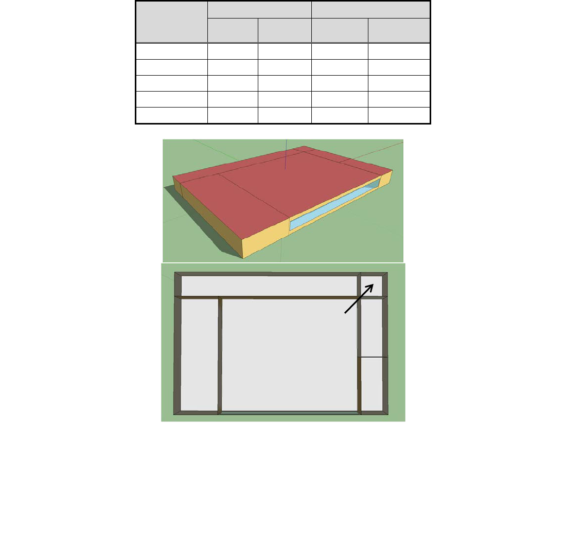
28
This report is available at no cost from the National Renewable Energy Laboratory (NREL) at www.nrel.gov/publications.
• Refrigeration: The produce, sales, deli, and bakery zones include a total of 1,064 linear
feet of refrigerated cases; walk-in freezers are located in the dry storage area (see Table
5–3). All the low-temperature and freezer cases are located in the sales zone. There are
four racks, each of which has four compressors. The case ASH power is controlled by
monitoring the dew point temperature in the space and linearly reducing the rated ASH
power to 0 at some user-specified space dew point. ASH power is a linear function of
indoor air dew point temperature, which is 58°F based on rated space conditions of 75°F
DB and 55% RH. Similarly, the refrigeration evaporator coil defrost energy is adjusted
according to a performance curve in EnergyPlus based on indoor air dew point
temperatures (DOE 2012b).
Table 5–3. Refrigeration System Case Length and Capacities
Zone
Case Length
Capacity (kW)
m
ft
Cases
Walk-in
Freezers
Produce
22 72 29 –
Sales
247
810
182
–
Deli
49 162 56 –
Bakery
6.0
20
8.7
–
Dry Storage
– – – 92
Figure 5–1. Supermarket schematic and floor layout.
Image by Lesley Herrmann, NREL
Dry Storage
Produce
Bakery
Deli
Sales
Office

29
This report is available at no cost from the National Renewable Energy Laboratory (NREL) at www.nrel.gov/publications.
5.1.1 Grocery Store Retrofitted with an LDAC
Continuing this example, an LDAC is installed to dehumidify 4,036 cfm of ventilation air, which
is ducted to the RTUs serving the sales and produce zones for sensible cooling. Because the
LDAC effectively eliminates the need for overcooling and reheating, the reheat coils were
removed. Characteristics of the LDAC are provided in Table 5–4. A schematic of a roof-
mounted LDAC system is shown in Figure 3–5.
Table 5–4. Example LDAC System Specifications
LDAC Model Input
Details
Outdoor air flow rate
• 4,036 cfm
Desiccant
• 42% LiCl
Cooling tower
• Chilled water temperature: Varies
• System sized to supply water at 7°F above
site’s design WB during design conditions
• Max fan power: 250 W
Natural gas boiler
• Efficiency: 0.8
• Capacity: 110 kW
• Hot water temperature: 176°F–194°F
Interchange heat exchanger
• Effectiveness of 0.8
The energy and utility costs savings as well as the LDAC incremental cost target estimates are
listed in Table 5–5, assuming a single-stage scavenging regenerator, and Table 5–6
shows the
increased savings when a two-stage regenerator is assumed. The application of the LDAC results
in a net source energy savings between 2% and 9% for the different reheat strategies analyzed in
this example. Although the application of the LDAC leads to an increase in site energy, utility
cost savings are achieved as a result of the building’s overall shift in fuel consumption from
electricity to natural gas. The site-to-source energy conversion factors for Houston, Texas, used
here are 1.092 for natural gas and 3.632 for electricity (Deru and Torcellini 2007). The market
cost of the LDAC cannot be determined at this point in time, so a detailed economic analysis is
not appropriate. Instead, the incremental cost target for the LDAC is calculated based on three-
and five-year simple payback periods. This gives a sense of how much more the LDAC should
cost compared to the baseline to be cost effective for building owners and for manufacturers to
achieve significant market uptake.
The benefits of using the LDAC for this application include:
• Cooling and fan energy savings: Cooling energy is significantly reduced by eliminating
the latent load from the ventilation air, which makes up most of the cooling requirement
in this climate zone. Fan energy savings are realized as a result of fewer heating and
cooling runtime hours.
• Refrigeration energy savings: Drier space conditions lead to reduced defrost and anti-
sweat energy.
• Lower average relative humidity: The annual average daily RH levels before and after
the LDAC is applied are 47% and 37%, respectively. Lower RH levels leads to better

30
This report is available at no cost from the National Renewable Energy Laboratory (NREL) at www.nrel.gov/publications.
product preservation by avoiding frost buildup on frozen foods and moisture collection in
packaged baked goods.
• Utility cost savings: Assuming the national average utility costs of $0.102/kWh for
electricity and $8.84/1,000 ft
3
(about 1 million BTU)
for natural gas (EIA 2013a,b), the
LDAC saves between $3,200 and $27,000 per year when a single-stage scavenging air
regenerator is used. When a two-stage regenerator is used, the LDAC saves between
$8,500 and $32,000 per year. Cost savings will vary depending on the base case used and
local utility charges. Maximum savings will be experienced against base cases with
electric resistance reheat and in locations where the ratio of electricity price to natural gas
price is highest.
• Improved space conditions: Grocery stores that depend on overcool/reheat are often
uncomfortably cold for employees and shoppers because moisture must be removed from
the space, but reheat is expensive. The use of the LDAC removes the moisture while
allowing warmer space temperatures, which improves overall occupant comfort.
Table 5–5. Energy Savings, Cost Savings, and Incremental LDAC Cost (Single-Stage Scavenging
Air Regenerator)
Baseline Reheat
Strategy
Source
Energy
Savings
(kBtu/ft
2
)
Site
Energy
Savings
(kBtu/ft
2
)
Utility
Cost
Savings
($)
3-Year Payback
Incremental
Cost Target
($)
5-Year Payback
Incremental
Cost Target
($)
Case 1) Natural Gas
3
-1.5
8,000
24,000
40,000
Case 2) RTU Hot
Refrigerant Gas +
Natural Gas
2
-4.1
3,200
9,600
16,000
Case 3) Electricity
9
-1.5
26,900
80,700
134,500
Case 4) RTU Hot
Refrigerant Gas +
Electricity
3
-7.2
9,000
27,000
45,000
Greater energy savings can be realized with the use of a two-stage regenerator, which is
predicted to use about 40% less natural gas for regeneration (see Table 5–6). The two-stage
regenerator will likely dominate over the single-stage regenerator in the market place. Further
energy savings are achievable if waste heat from the RTU or refrigeration system is used for
regeneration. However, this strategy can also be used by vapor compression systems to reduce
reheat energy. The incremental cost of the LDAC system will be critical in competing with these
systems, as shown in row 2 of Table 5–5 and Table 5–6.

31
This report is available at no cost from the National Renewable Energy Laboratory (NREL) at www.nrel.gov/publications.
Table 5–6. Energy Savings, Cost Savings, and Incremental LDAC Cost (Two-Stage Regenerator)
Baseline Reheat
Strategy
Source
Energy
Savings
(kBtu/ft
2
)
Site
Energy
Savings
(kBtu/ft
2
)
Utility Cost
Savings
($)
3-Year
Payback
Incremental
Cost Target
($)
5-Year
Payback
Incremental
Cost Target
($)
Case 1) Natural Gas
5
4
13,000
40,000
67,000
Case 2) RTU Hot
Refrigerant Gas +
Natural Gas
4
1
8,500
25,600
42,600
Case 3) Electricity
11
4
32,200
96,600
161,000
Case 4) RTU Hot
Refrigerant Gas +
Electricity
5
-1
14,300
42,900
71,500
There will be some additional maintenance costs associated with the LDAC.. Under normal
operating conditions, maintenance will include filter replacement and desiccant concentration
monitoring, which can be simplified with hydrometers. In cold climates, winterization of the
system consists of draining the cooling water from the conditioner and the heat transfer fluid
from the regenerator (if it is water). Water in the cooling tower should also be drained if such
equipment is used. Additional costs associated with maintaining the cooling tower will exist.
5.2 Design Considerations
There are a number of key design considerations to be aware of when installing an LDAC system
on a grocery store as part of a new construction or retrofit project:
• Maintain manageable infiltration rates: High infiltration rates resulting from doors
being unnecessarily left open or poor envelope integrity can lead to latent loads that
exceed design conditions. If a building’s HVAC system is not appropriately sized to
accommodate the additional latent loads, condensation may become an issue and lead to
product degradation, frost buildup on freezer shelves, and fog on refrigerated case doors
(see Figure 5–2). Strategies for infiltration control should be thoroughly considered.
More information on infiltration control and door operation schedules can be found in
Retail Building Guide for Entrance Energy Efficiency Measures (DOE 2012c).

32
This report is available at no cost from the National Renewable Energy Laboratory (NREL) at www.nrel.gov/publications.
Figure 5–2. Effects of high grocery store humidity levels on refrigerated cases.
Photos by Ian Doebber, NREL
• Introduce LDAC supply air in the refrigeration section: To achieve the highest
possible energy savings, introduce the dehumidified air in the refrigeration section of the
store, specifically above: (1) open low-temperature cases (i.e., coffin cases); (2) open
multideck dairy and deli cases; or (3) low-temperature cases. Providing dry air to this
area of the store will help minimize refrigeration defrost and anti-sweat energy.
Introducing LDAC air directly above the produce is not recommended because the
extremely dry air will tend to dry out the product.
• Program refrigeration control strategies to respond to store conditions: ASHs and
defrost cycles should be programmed to cycle in response to freezer conditions and
evaporator coil conditions, respectively. In standard operation, ASHs operate at full
power 100% of the time; however, the controllers can be set to monitor the dew point
temperature of the indoor air and adjust the duty cycle of the heaters appropriately.
Defrost heaters can be programmed to shut off when the measured air temperature
discharged from the evaporator coil indicates the absence of frost. It is also beneficial to
allow suction temperatures to float in response to case conditions. This is a standard
control feature of the refrigeration system controller that allows the compressor rack to
maintain a warmer suction temperature in response to demand and still provide enough
cooling to the most demanding case on the rack to maintain the case set point.
• Include options for ventilation supply: In very humid climates (including climate zones
1A and 2A), the design engineer should consider processing all the ventilation air with
the LDAC (i.e., close the outdoor air dampers in all the other zone equipment).
Other publications that offer energy saving strategies in grocery stores include:
• Advanced Energy Retrofit Guide (AERG) for Grocery Stores (DOE 2012a)
• Thinking Like a Whole Building: A Whole Foods Market New Construction Case Study
(DOE 2011).

33
This report is available at no cost from the National Renewable Energy Laboratory (NREL) at www.nrel.gov/publications.
6 Pool Facilities
Maintaining comfortable and healthy environments in water parks, natatoriums, and indoor pools
can be challenging. The continuous evaporation of pool water imposes both a large latent load on
the facility and a large heating load on the pool. Furthermore, the chemical treatments required to
keep pool water clean create high ventilation requirements, which can then impose additional
latent loads on the facility in humid climates.
Installing an LDAC to control humidity in pool facilities has many possible advantages.
However, it is critical to consult with the LDAC manufacturer to ensure chemical compatibility
between the zone air, which includes trace chemicals such as chlorine gas, and the choice of
liquid desiccant. This will avoid precipitates forming within the LDAC’s desiccant-containing
components, which can cause clogs.
LDAC operation and the effects of pools on space conditions are complementary in many ways.
The pool continuously generates latent loads in the space through evaporation, which sensibly
cools the pool water. Simultaneously, the LDAC continuously removes latent loads from the air
while generating heat of sorption that can be rejected to the pool water. This creates a cycle in
which energy is continuously conserved within the pool space.
Both LDAC and DX systems have comparable abilities to move air and circulate water;
however, the biggest difference in their electrical loads is the DX system’s compressor. Based on
manufacturer data, DX compressors will have an electrical efficiency of about 1 kW/ton; when
taking reheat into account, this value increases to about 1.5 kW/ton. In comparison, the LDAC
will have an electric efficiency of about 0.4 kW/ton.
In addition, the LDAC offers ancillary benefits in natatoriums, including:
• Providing most of the latent cooling to the space and reducing the load on the cooling
coils
• Providing dry air that can be used as a method to replace hot air jets with dry/cool air jets
to control condensation on perimeter windows
• Providing drier air than is possible with a vapor compression unit.
These features allow independent control of space humidity and sensible loads, which can
eliminate the process of overcool-and-reheat. Figure 6–1 shows an example of an LDAC
integrated with a pool facility. In this example, the supply and return ductwork layout has been
simplified for conceptual clarity, and the LDAC is located outside the building. Heat exchanger
#4 in the diagram is a counter flow exchanger that transfers the heat of sorption from the
conditioner water loop to the pool water loop.

34
This report is available at no cost from the National Renewable Energy Laboratory (NREL) at www.nrel.gov/publications.
Figure 6–1. LDAC system integrated with a swimming pool.
Image by David Goldwasser and Marjorie Schott, NREL
One advantage of using LDAC or DX air conditioners in pool facilities is that rejected thermal
energy from these systems can be used to counter the continuous evaporative cooling of the pool
water. The ratio Q
to pool
/Q
evaporation
describes the amount of heat delivered to the pool water (in the
form of waste heat from the LDAC’s conditioner) compared to the heat lost by the pool from
evaporative cooling. If this ratio is much greater than 1.0, the pool may overheat. LDAC systems
can maintain a fairly steady Q
to pool
/Q
evaporation
ratio of about 1.2 which is ideal; the DX
dehumidification systems can achieve ratios as high as 3.2 requiring supplemental heat removal
(Lowenstein 2013). This ratio ultimately determines the scale of heat-rejection requirements for
each system. DX systems often use auxiliary condensers with heat rejection capacities on the
order of 1,000 kBtu/h; in comparison, the LDAC, if it requires auxiliary cooling at all, may use a
small cooling tower with heat rejection capacities only on the order of 100 kBtu/h (Lowenstein

35
This report is available at no cost from the National Renewable Energy Laboratory (NREL) at www.nrel.gov/publications.
2013). This heat removal is not a trivial task for a DX system, as dual condensing circuits (one
heating the pool and another rejecting to ambient) operating at different heat rejection
temperatures would need to be implemented. Such a system would most likely need refrigerant
diverting valves to accomplish this, which tend to be high maintenance. Furthermore, the
LDAC’s heat rejection requirement is small enough that it is reasonable to eliminate it altogether
and accept pool temperatures on the order of 2°F higher than the pool set point during warm
weather months. In either case, the LDAC offers capital cost reductions from the use of smaller
(or no) heat rejection equipment. Furthermore, the LDAC system has minimal maintenance
requirement (refer to Section 5.1.1 for recommended maintenance).
6.1 Design Considerations
There are a couple of items to account for when considering installation of an LDAC system at a
pool facility:
• The use of the LDAC will result in a shift from electrical energy to thermal energy. In
many cases, a natural gas boiler may be the most feasible heating source. In other cases,
thermal energy could be provided by waste heat from, for example, a cogeneration
system.
• The LDAC and sensible cooling system will work in conjunction to keep humidity and
DB temperature under control. If a vapor compression system is being used for sensible
cooling, there is a certain amount of latent cooling that will also occur at the evaporator
coil. The LDAC and vapor compression system should be sized optimally together to
take advantage of this “free” latent cooling. Therefore, a holistic HVAC design approach
is needed to ensure proper space humidity and temperature control. The facility manager
and the LDAC manufacturer should work together to establish appropriate sensible and
latent load calculations for the space (see Section 3.3).

36
This report is available at no cost from the National Renewable Energy Laboratory (NREL) at www.nrel.gov/publications.
7 References
Abdou, O.; Elkholy, G.; Abdou, A. (n.d.). Correlation Between Indoor Environmental Quality
and Productivity in Buildings. Accessed October 8, 2013:
http://www.academia.edu/1013680/Correlation_between_Indoor_Environmental_Quality_and_P
roductivity_in_Buildings.
ASHRAE (2007a). ANSI/ASHRAE/IESNA Standard 62.1-2007, The Standards for Ventilation
and Indoor Air Quality. Atlanta, GA: American Society of Heating, Refrigerating and Air-
Conditioning Engineers, Inc.
ASHRAE (2013). ASHRAE Handbook: Fundamentals. Atlanta, GA: American Society of
Heating, Refrigerating and Air-Conditioning Engineers, Inc.
Conde-Petit, M.; Huber-Strasse, E. (2007). “Liquid Desiccant-Based Air-Conditioning Systems –
LDACs.” Proc. First European Conference on Polygeneration. Zurich, Switzerland; pp. 217–
234. Accessed October 11, 2013: http://six6.region-
stuttgart.de/sixcms/media.php/773/19_Conde_M.pdf.
Deru, M.; Torcellini, P. (2007). Source Energy and Emission Factors for Energy Use in
Buildings. NREL/TP-550-38617. Golden, CO: National Renewable Energy Laboratory.
DOE (2004). Guide to Determining Climate Regions by County. Developed for the U.S.
Department of Energy and first published in ASHRAE Standard 90.1-2004. Accessed December
21, 2012:
http://apps1.eere.energy.gov/buildings/publications/pdfs/building_america/ba_climateguide_7_1.
pdf.
DOE (2012a). Advanced Energy Retrofit Guide (ARDG) for Grocery Stores. Accessed
September 22, 2013:
http://apps1.eere.energy.gov/buildings/commercial/resource_database/detail.cfm?p=563.
DOE (2012b). EnergyPlus Engineering Reference. Washington, D.C.: U.S. Department of
Energy.
DOE (2012c). Retail Building Guide for Entrance Energy Efficiency Measures. Accessed August
9, 2013: http://www.nrel.gov/docs/fy12osti/52290.pdf.
DOE (2011). Thinking like a Whole Building: A Whole Foods Market New Construction Case
Study. Accessed September 22, 2013: http://www.nrel.gov/docs/fy11osti/50056.pdf.
EIA (2012a). Average Retail Price of Electricity to Ultimate Customers. Accessed August 2013:
http://www.eia.gov/electricity/monthly/epm_table_grapher.cfm?t=epmt_5_03.
EIA (2012b). Average Price of Natural Gas Sold to Commercial Consumers, by State, 2010–
2012. Accessed August 2013: http://www.eia.gov/naturalgas/monthly/pdf/table_21.pdf.

37
This report is available at no cost from the National Renewable Energy Laboratory (NREL) at www.nrel.gov/publications.
ENERGY STAR (2013). Source Energy. PortfolioManager Technical Reference. Accessed
October 2013:
https://portfoliomanager.energystar.gov/pdf/reference/Source%20Energy.pdf?46e0-4737.
Faramarzi, R.; Sarhadian, R.; Sweetser, R.S. (2000). “Assessment of Indoor Relative Humidity
Variations on the Energy Use and Thermal Performance of Supermarkets' Refrigerated Display
Cases.” 2000 American Council for an Energy Efficient Economy Summer Study on Energy
Efficiency in Buildings, Panel 3, Commercial Buildings: Technologies, Design, and Performance
Analysis. Accessed December 27, 2012:
http://eec.ucdavis.edu/ACEEE/2000/PDFS/PANEL03/582.pdf.
Khattar, M.; Henderson, H. (1999). “Impact of HVAC Control Improvements on Supermarket
Humidity Levels.” ASHRAE Transactions (105:1). Atlanta, GA: American Society of Heating,
Refrigerating and Air-Conditioning Engineers, Inc.
Kosar, D.; Dumitrescu, O. (2005). “Humidity Effects on Supermarket Refrigerated Case Energy
Performance: A Database Review.” ASHRAE Transactions (111:1); pp. 1051–1060. Atlanta,
GA: American Society of Heating, Refrigerating and Air-Conditioning Engineers, Inc.
LBNL. (2013). Impacts of Indoor Environments on Human Performance and Productivity: Cost
Effectiveness of Improving Indoor Environments to Increase Productivity. Berkeley, CA:
Lawerence Berkeley National Laboratory Indoor Air Quality Scientific Findings Resource Bank.
Accessed October 8, 2013: http://www.iaqscience.lbl.gov/performance-cost.html.
Lowenstein, A.; Slayzak, S.; Kozubal, E. (2006). “A Zero Carryover Liquid-Desiccant Air
Conditioner for Solar Applications.” Proc. ISEC2006 ASME International Solar Energy
Conference. Denver, CO.
Lowenstein, A. (2013). Interview. AIL Research, Hopewell, NJ. August 10, 2012. Interviewer:
Lesley Herrmann, NREL.
Lowenstein, A. (2008). “Review of liquid desiccant technology for HVAC applications.”
HVAC&R Research (14); pp. 819–839.
NREL. (2008). Users Manual for TMY3 Data Sets. NREL/TP-581-43156. Golden, CO: National
Renewable Energy Laboratory. Accessed October 20, 2013:
http://www.nrel.gov/docs/fy08osti/43156.pdf.
NREL. (2013). Low-Flow Liquid Desiccant Air-Conditioning: Demonstrated Performance and
Cost Implication. NREL/TP-5500-60698. Golden, CO: National Renewable Energy Laboratory.
