
Laser PFIB for large-volume 3D EBSD:
a correlative microscopy perspective
Application note
Authors
Bartłomiej Winiarski, Ph.D.,
Thermo Fisher Scientific.
The Thermo Scientific
™
Helios
™
Laser Hydra System
features our most recent advances in multi-beam
instrumentation, combining a femtosecond laser with a
rapidly switchable multi-ion species plasma focused ion
beam (PFIB) and a field-emission gun scanning electron
microscope (FEG-SEM). This combination expands the
boundaries of traditional Thermo Scientific
™
DualBeam
™
Technology to deliver high-quality macroscale cross-
sections for rapid, large-volume analysis of challenging
materials at nanometer resolution.
Introduction
The advent of commercial FIB-SEM in
the 2000s enabled automated serial-
sectioning tomography, 3D-energy-
dispersive spectroscopy (3D-EDS), and
3D electron-backscatter diffraction
(3D-EBSD) of material volumes smaller
than 40×40×40 µm³. Since 2015, Xe⁺
plasma FIB-SEM (PFIB-SEM) has
expanded these techniques to volumes
of ~250×250×250 µm³, with voxels
approximately dozens of nanometers
in size. Since 2019, the addition of
femto-second laser ablation to Xe⁺ PFIB-SEM pushed these 3D techniques further to
millimeter-scale volumes,
1-3
raising the standard for multi-modal data collection from
nanometers to millimeters. In 2021, fast-switching multi-ion PFIB (Xe⁺, O⁺, Ar⁺, or N⁺)
further extended the applications of laser PFIB.
Figure 1. 3D volume of an aluminum alloy
obtained with laser serial sectioning.² Images
were rendered in Dream 3D, freeware software
for 3D EBSD post-processing and visualization.
640 μm
570 μm
660 μm

C
D
B
PFIB
Adapter
SEM
Laser
CT
post
Sample
holder
These “DualBeam” and “TriBeam” platforms fit seamlessly
in multi-scale and multi-modal correlative microscopy (CM)
methodologies. CM workflows coordinate the characterization
of materials across a range of length scales to solve scientific
problems in 2D and 3D, including time-resolved experiments.
Correlative microscopy in materials and life sciences can
use a number of potential 3D methods such as micro/nano
X-ray computed tomography, optical microscopy, (P)FIB-
SEM, transmission electron microscopy (TEM), as well as
nano-computed tomography in TEM and SEM.
4,5
Combining
these methods for the same region of interest at different length
scales allows 2D/3D spatial and temporal registration of many
imaging modalities, i.e., visible light, cathodoluminescence,
and electron imaging, ion microscopy, EBSD, WDS and EDS
analytics, X-ray tomography, magnetic resonance imaging,
Raman, atomic force microscopy, etc.
Figure 2 demonstrates various 3D data collection techniques
used in material science and the length scales they can
access.⁶ Figure 3 shows the serial sectioning techniques used
for 3D EBSD.¹
This application note discusses current developments in 3D
EBSD for correlative microscopy, using the laser multi-ion PFIB-
SEM. A study from The University of Manchester is highlighted
as a practical example, where the CM workflow is applied to
the large-volume analysis of environmentally assisted cracks in
7xxx alloys.²
Methods
3D correlative microscopy/tomography workflow
The basic workflow (Figure 4a) uses the Helios Laser Hydra
System together with a micro X-ray computed tomography
(X-ray µCT) scanner, a cross-platform holder/adapter kit
(Figure 4b), and Thermo Scientific
™
Avizo
™
3D Software. The
workflow can be extended to 3D nanoscale investigations using
TEM and/or atom probe tomography (APT) (Figure 2).
Femtosecond laser PFIB-SEM
The Helios Laser Hydra System is built on the fifth generation
of the Thermo Scientific
™
Helios Hydra
™
DualBeam platform
(Figure 5) and includes a fully enclosed femtosecond laser
optical path. The laser beam, electron, and multi-ion columns
are positioned on a plane and oriented toward a single point.
The fs-laser beam supports two wavelengths: 1030 nm (IR) and
515 nm (green). Fs-laser ablation is an athermal process that
enables material removal without thermal melting. In general
terms, thermal diffusion is slower than the Coulombic explosion
in femtosecond laser ablation, resulting in only a nanometer-
size heat-affected zone (HAZ). Material removal by the fs-
laser, meanwhile, is an order of magnitude higher than what is
possible with a Xe⁺ PFIB system.
Figure 2. 3D imaging methods for materials science. SST = serial
sectioning tomography.⁶
Figure 3. Serial sectioning techniques for 3D EBSD, including the size of
data collected, based on Reference 1. BIB = broad ion beam.
Figure 4. a) The 3D correlative microscopy/tomography workflow. Red
arrows indicate sample transfer, blue arrows mark data transfer. b) Cross-
platform holder/adapter kit. c) Sample and holder in the µCT. d) Sample
and holder in the Helios Laser Hydra System.
A
Sample preparation
Sample transfer
Data processing,
alignment, and
co-registration
Visualization, data
fusion, and mining
Multimodal data
acquisition,
micro sample
preparation,
STEM
Survey, high
resolution
scan, and ROI
navigation
Reconstructed CT volume
3D micro XCT
virtual sections
X-platform holder MicroCT
Helios 5 Laser Hydra
System Maps Software
Avizo Software
3D EBSD workflows
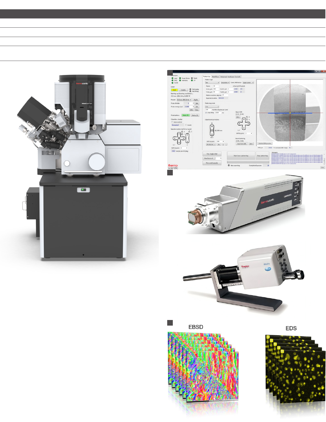
3D EBSD workflows are controlled and customized in the laser
UI (Figure 6a) or via Python scripting application programing
interface (API). These channels control acquisition hardware
(Figure 6b) and software. During an automated run, various 2D
datasets are sequentially collected (Figure 6c) and assembled
in 3D with Avizo 3D Software as well as any other EBSD
evaluation packages.
Laser PFIB-SEM stage positions for 3D EBSD data collection
(shown in Figure 7) are automatically cycled through as the data
is collected in sequence. Some materials require additional
surface polishing of the laser-ablated cross-section to remove
laser-induced periodic surface structures (LIPSS), as shown in
Figure 7e and 7f. These periodic structures can be suppressed
by fine tuning of laser parameters such as wavelength,
repetition rate, pulse energy, etc.
7,8
Figure 6. 3D EBSD with Helios Laser Hydra PFIB-SEM. A) Automation is
enabled with the laser UI or the Python scripting API.. B) Available EBSD
(top) and EDS (bottom) data acquisition hardware. C) Resulting multimodal
serial sections data.
Comparison of 3D EBSD parameters for various serial sectioning techniques
Ga FIB Xe PFIB Laser PFIB Xe PFIB SM* Broad IB Mech. Polish.
Slice thickness (nm) 5-50 25-500 250-10,000 1-1,000 10-10,000 200-10,000
Slice rate (µm³/s) 20 400 40,000 400 33 100,000-50,000
Max sample size (µm) 50x50 400x400 2,000x2,000 800x800 300x300 50,000x50,000
Damage depth (nm)
Si amorphisation
3-22 2.5 -13 20-50 2.5-13 <30 35-60
* Spin milling
A
B
C
Figure 5. The Thermo Scientific Helios Laser Hydra System.
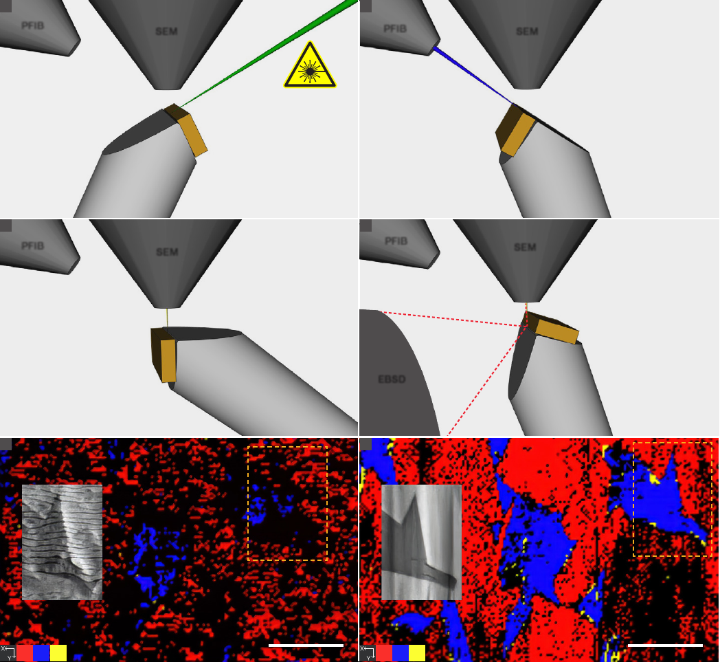
Figure 7. Laser PFIB-SEM stage positions for 3D EBSD data collection. a) Layer removal with laser. b) Optional surface polishing with PFIB. c) SEM (EDS)
data mapping. d) EBSD (EDS) data collection. e) EBSD phase map of WC-11 wt% Co after laser ablation. SEM-SE inset shows the LIPSS pattern. f) EBSD
phase map after additional PFIB cleaning. SEM-SE inset shows PFIB polished surface.
Customer case study
Figure 8 shows correlative microscopy results from The
University of Manchester on stress corrosion cracking in an
AA7050 aluminum alloy, combining X-ray analysis with large-
volume 3D EBSD.²
Correlative microscopy was used to precisely locate regions
of interest and conduct multiple studies in order to better
understand the drastically different environmentally assisted
cracking (EAC) behaviors of the aviation and aerospace alloys
AA7050 and AA7085. For more experimental and scientific
details see Reference 2.
PFIB
SEM
~ 0 degrees
B
PFIB
SEM
~ 90 degrees
C
PFIB
SEM
~ 70 degrees
D
EBSD
PFIB
SEM
~ 0 degrees
A
CoCoWC
5 μm
E
CoCoWC
5 μm
F

Acknowledgements
We would like to thank Prof. Tim L. Burnett and Prof. Philip
J. Withers of The University of Manchester for allowing us to
highlight their work in this application note.
References
1. Echlin, MP, et al. Recent Developments in Femtosecond Laser-Enabled TriBeam
Systems. JOM 73, 4258–4269 (2021)
2. Garner, A, et al. Large-scale serial sectioning of environmentally assisted cracks in
7xxx Al alloys using femtosecond laser-PFIB. Mater Charact 188:111890 (2022)
3. Winiarski, B and Geurts, R. Laser Xe+ Plasma FIB-SEM: Correlative microscopy of
3D microstructures from nanometers to millimeters. Wiley Analytical Sci. Magazine
(2020)
4. Winiarski, B, at al. Correlative Tomography for Additive Manufacturing of Biomedical
Implants. Microscopy and Microanalysis 31(6), S4-S9 (2017)
5. Burnett, LT, et al. Correlative Tomography. Scientific Reports 4:4711 (2014)
6. Burnett, LT, et al. Large volume serial section tomography by Xe Plasma FIB dual
beam microscopy. Ultramicroscopy 161, 119-129 (2016)
7. Winiarski, B, and Geurts, R. Proceedings of the 6th International Congress on 3D
Materials Science, Washington, DC. (2022)
8. Jelinek, A, at al. A Perspective to Control Laser-Induced Periodic Surface Structure
Formation at Glancing-Incident Femtosecond Laser-Processed Surfaces. JOM 73,
4248–4257 (2021)
Summary
Correlative microscopy, combining µCT for site targeting
with laser PFIB-SEM for serial sectioning, allowed for precise
access to a large volume of material containing EAC cracks.
This high-resolution SEM study has provided new insight
into the interactions between microstructure and EAC cracks
in aluminum alloys, particularly in relation to the size and
morphology of the grains, as well as deviations in crack
direction. A novel, optimized lift-out procedure for large-scale
serial sectioning was also developed by researchers from
The University of Manchester, which can be used for similar
scientific and industrial research problems.
The Thermo Scientific Helios Laser Hydra System offers
researchers the unique opportunity to perform 3D analysis of
beam-sensitive and difficult-to-mill microstructures with sizes
ranging from nanometers to millimeters. This range of scales
helps bridge the gap between conventional Ga⁺ FIB and 3D
X-ray tomography. The Helios Laser Hydra System is ideally
suited for the correlative tomography workflow by coupling
micro X-ray CT with serial sectioning tomography while also
enabling multiple types of data (structural, crystallographic,
chemical, etc.) to be brought into registry for the same region.
D
570 µm
C
1 μm
B
3D-EBSD using femtosecond laser plasma FIB-SEMX-ray CT survey scan X-ray CT high-resolution scan
6 mm
A
60 mm
15 mm
6 mm
640
µm
660
µm
A B C
D
Figure 8. Correlation of X-ray CT datasets and laser serial sectioning for an AA7050 alloy.² a) Initial survey XCT scans with overlaid high-resolution ROI
scans of the crack tip region. The metal is rendered transparent, and the cracks are shown in dark blue. b) High-resolution ROI XCT scan with each
isolated crack feature colored differently (i.e., the crack front is split into separate fingers) within the volume. Approximate positions of the volumes
extracted for serial sectioning analysis are also shown. c) 3D reconstruction of the crack path (shown in dark blue). D) The entire 3D volume of the laser
serial sectioned specimen. Images were rendered in Dream 3D, freeware software for 3D EBSD post-processing and visualization. Data courtesy of The
University of Manchester, UK
For research use only. Not for use in diagnostic procedures. For current certifications, visit thermofisher.com/certifications
© 2023 Thermo Fisher Scientific Inc. All rights reserved. All trademarks are the property of Thermo Fisher Scientific
and its subsidiaries unless otherwise specified. AN0218-EN-04-2023
Learn more at thermofisher.com/tribeam
