
DECISION GUIDE
A Guide for Selecting Remedies for Subsurface Releases of
Chlorinated Solvents
ESTCP Project ER-200530
MARCH 2011
Dr. Tom Sale
Colorado State University
Dr. Charles Newell
GSI Environmental, Inc.

A Guide for Selecting Remedies for Subsurface Releases of Chlorinated Solvents i
This document is a product of the
Department of Defense Environmental Security
Technology Certification Program (ESTCP)
This “Guide for Selecting Remedies for Subsurface Releases of Chlorinated
Solvents” provides an overview of current knowledge regarding management of
subsurface chlorinated solvent releases. The envisioned audience is state
regulators, federal regulators, consultants, DoD staff, and community members
involved in selecting remedies for chlorinated solvent sites.
The document is intended to provide current knowledge in support of sound
decisions. It is not intended to foster or discourage efforts to clean up subsurface
releases, but to help practitioners who are faced with difficult decisions, and to lay
the groundwork for developing realistic expectations regarding the outcome of such
treatments. Our hope is that the document contributes to better use of resources,
more effective remediation and risk management, and more productive cooperation
between the parties involved in site cleanups.
In the interest of brevity, the Guide and its companion document, “Frequently
Asked Questions Regarding Management of Chlorinated Solvents in Soils and
Groundwater”, assume that the reader has a general understanding of
hydrogeology, the movement of chemicals in porous media, remediation
technologies, and the overall remedy selection process.
The authors of the this document wish to acknowledge the financial support of
ESTCP for this project and the important contributions of researchers, scientists, and
engineers who have built the knowledge base upon which this document stands.
THE COVER and other portions of this document include lithographic prints from John Wesley
Powell’s The Exploration of the Colorado River and Its Canyons (used with permission from Dover
Publications, Inc.). Much like Powell’s 1869 survey of the Colorado River, our effort to resolve
issues posed by subsurface releases of chlorinated solvents has been a journey into the unknown.
Fortunately, as was the case with Powell’s endeavors, experience has been a keen instructor.
Through the knowledge we have gained, we now stand well prepared to find pragmatic solutions
for managing chlorinated solvents in subsurface environments.

A Guide for Selecting Remedies for Subsurface Releases of Chlorinated Solvents ii
Authors
Dr. Tom Sale is an Associate Professor at Colorado State University in the Department
of Civil and Environmental Engineering. He has been actively involved in the
characterization and remediation of subsurface releases of Nonaqueous Phase Liquids
(NAPLs) since 1981. Dr. Sale received his Ph.D. in Agricultural Engineering in 1998 from
Colorado State University. He has a M.S. in Watershed Hydrology from the University of
Arizona (1984) and B.A. degrees in Geology and Chemistry from Miami University,
Oxford, Ohio (1980).
Dr. Charles Newell is a Vice President with GSI Environmental, an environmental
consulting firm located in Houston, Texas. He has a B.S. in Chemical Engineering and
M.S. and Ph.D. degrees in Environmental Engineering from Rice University. He is a
member of the American Academy of Environmental Engineers and is an Adjunct
Professor in the Department of Civil and Environmental Engineering at Rice University.

A Guide for Selecting Remedies for Subsurface Releases of Chlorinated Solvents iii
Contents
Section 1 – Introduction ................................................................................................... 1
Section 2 - Understanding the Problem .......................................................................... 5
Processes Governing the Movement and Distribution of Chlorinated Solvents in
Subsurface Environments .............................................................................................. 6
DNAPL ................................................................................................................... 8
Vapor Phase ........................................................................................................ 11
Aqueous Phase .................................................................................................... 12
Sorbed Phase ...................................................................................................... 17
Critical Attributes of Common Geologic Settings ......................................................... 19
Geologic Type Settings ........................................................................................ 19
Type I – Granular Media with Mild Heterogeneity and Moderate to High
Permeability ......................................................................................................... 20
Type II – Granular Media with Low Heterogeneity and Low Permeability .......... 21
Type III – Granular Media with Moderate to High Heterogeneity ........................ 21
Type IV - Fractured Media with Low Matrix Porosity ........................................... 22
Type V – Fractured Media with High Matrix Porosity ........................................... 24
Source Zones Containing Multiple Type Settings ................................................ 25
Summary of Type Settings ................................................................................... 26
Evolution of Chlorinated Solvent Releases as a Function of Setting and Time ........... 27
The Effects of Source Depletion or Source Containment on Water Quality ............... 32
The Big Picture ..................................................................................................... 33
Source Function ................................................................................................... 34
Plume Response - Overview ............................................................................... 36
Summary ...................................................................................................................... 44
Section 3 - Formulating Objectives ............................................................................... 46
Types of Remediation Objectives ................................................................................ 48
Attributes of Good Functional Objectives ..................................................................... 49
Common Objectives for Remediation Projects ............................................................ 51
Summary of Objectives from Key Regulatory and Technical Sources ....................... 52
USEPA’s Nine Criteria ......................................................................................... 52
Risk-Based Corrective Action (RBCA) ................................................................. 53
2003 EPA Expert Panel on DNAPL ..................................................................... 54
National Research Council and Remedial Objectives ......................................... 55
Sustainability Remediation Movement ................................................................. 56
Section 4 - Resolving What is Attainable ..................................................................... 58
Overview ...................................................................................................................... 58
Proven Technologies ................................................................................................... 59
Technology Evaluation ................................................................................................. 59
Treatment Technologies .............................................................................................. 61
Overview .............................................................................................................. 61
Recovery Technologies ....................................................................................... 62
Pump and Treat (for depletion vs. containment) .................................................. 62
Excavation ............................................................................................................ 68
Soil Vapor Extraction (SVE) ................................................................................. 71
In Situ Degradation ...................................................................................................... 74

A Guide for Selecting Remedies for Subsurface Releases of Chlorinated Solvents iv
Thermal ..................................................................................................................... 74
In Situ Chemical Reduction (ISCR) .......................................................................... 78
In Situ Chemical Oxidation (ISCO) ........................................................................... 80
In Situ Biological Treatment ...................................................................................... 83
Containment ................................................................................................................. 86
Hydraulic Controls ..................................................................................................... 87
Physical Barriers ....................................................................................................... 89
Permeable Reactive Barriers (PRBs) ....................................................................... 92
Section 5 - Developing Packages of Remedial Measure ............................................ 95
Example 1 – A Large Instantaneous Release of PCE DNAPL .................................... 96
Site Conceptual Model ......................................................................................... 96
Objectives ............................................................................................................ 98
Advancement of a Package of Remedial Measures ............................................ 99
Example 2 – A Small Release of TCE after 10 years of Hydraulic Containment ...... 107
Site Conceptual Model ....................................................................................... 107
Objectives .......................................................................................................... 111
Advancement of a Package of Remedial Measures .......................................... 113
Example 3 –Release of TCE in a Regional Water Supply Aquifer ............................ 119
Site Conceptual Model ....................................................................................... 119
Objectives .......................................................................................................... 122
Advancement of a Package of Remedial Measures .......................................... 123
Section 6 - Limitations .................................................................................................. 125
Project Scope ............................................................................................................. 125
Governing Processes ................................................................................................. 125
Performance of Remedial Technologies .................................................................... 126
The 14 Compartment Model ...................................................................................... 126
Section 7 - References by Section .............................................................................. 129
Section 1 .................................................................................................................... 129
Section 2 .................................................................................................................... 129
Section 3 .................................................................................................................... 132
Section 4 .................................................................................................................... 133

A Guide for Selecting Remedies for Subsurface Releases of Chlorinated Solvents v
Figures
Figure 1 - Immiscible fluids in the pore space of a granular porous media
(after Wilson et al., 1990) ............................................................................................ 8
Figure 2 – Examples of DNAPL architecture (Feenstra et al., 1996). .............................. 10
Figure 3 - Diffusion into and out of low permeability materials, leading to
initial plume attenuation and subsequent long-term plume
persistence (AFCEE, 2007). ..................................................................................... 15
Figure 4 – Fractions of total contaminant mass in the aqueous and
sorbed phases as a function of the fraction of organic carbon
(Following Schwarzenbach et al. (1993), using parameters for
typical saturated soils and K
oc
values from Allen-King et al., (1996)). ...................... 18
Figure 5 – Geologic Type Settings (NRC 2005) .............................................................. 19
Figure 6 - Examples of Type I media (Great Sand Dunes National Park
web site) .................................................................................................................... 20
Figure 7 - Interbedded sandstone and shale, an example of Type III
media. Photo provided by Fred Payne – ARCADIS. ............................................... 22
Figure 8 - Fractured crystalline rock, an example of Type IV media
(Cache La Poudre River, Colorado) Photo provided by Tom Sale . ......................... 23
Figure 9 - Bedding planes, joints, and vertical fractures in carbonate
rock, Ontario, Canada (Courtesy of Dr. Beth Parker). .............................................. 24
Figure 10 - Large- and small-scale solution features in karst limestone,
Redstone Arsenal (Courtesy of De la Paz and Zondlo, Shaw
Engineering). ............................................................................................................. 25
Figure 11 – Evolution of a chlorinated solvent release in a Type III
setting as a function of time. Red, yellow, and green compartments
indicate high, moderate, and low importance of the compartments,
respectively. Noted conditions are plausible, but not necessarily the
only possibility. .......................................................................................................... 28
Figure 12 – Illustration of plausible distributions of chlorinated solvent as
a function of type setting and the stage of release. Gray boxes are
considered to be absent in the type setting. Red, yellow, and green
compartments indicate high, moderate, and low importance of the
compartments, respectively. Note that conditions presented are
plausible in the noted situations, but not necessarily the only
possible scenario. ..................................................................................................... 29
Figure 13 – Six primary scenarios of concern for chlorinated solvent
releases. .................................................................................................................... 30
Figure 14 – Use of multiple 14 Compartment Models to describe a
complex site. ............................................................................................................. 31
Figure 15 - Temporal Concentration Records for Wells at Source
Depletion Sites .......................................................................................................... 36
Figure 16 - Field data from F.E. Warren AFB (courtesy of F.E. Warren
AFB and AFCEE). ..................................................................................................... 38

A Guide for Selecting Remedies for Subsurface Releases of Chlorinated Solvents vi
Figure 17 - Simulated plume concentration (ug/L) after 90% reduction in
source mass + remediation of first 400 meters of plume, both
occurring in 2005 ...................................................................................................... 41
Figure 18 - Sensitivity concentrations in wells to contaminant half-life,
retardation coefficient, and downgradient distance from source. ............................. 43
Figure 19 – Pump and Treat performance mapped using the 14
Compartment Model. Arrows indicate potentially induced releases
from other compartments. The dashed arrows indicate a
speculative response depending on site conditions. Note that
greater depletion could be achieved through longer periods of
pumping. The above is intended to be reflective of several years
(versus several decades) of pumping. ...................................................................... 64
Figure 20 – Plausible distribution of chlorinated solvents in a late stage
Type 4 setting (fractured rock with low matrix porosity) ........................................... 65
Figure 21 – Anticipated outcome from source zone pump and treat in a
late-stage Type IV setting. Boxes in the “Tech” columns show
estimated performance of remedial action based on the number of
OoMs of concentration reduction. “After” values equal “before”
values minus “Tech” values. ..................................................................................... 66
Figure 22 - Anticipated outcome from source zone pump and treat in a
middle stage Type 3 setting. Boxes in the “Tech” columns show
estimated performance of remedial action based on number of
OoMs of concentration reduction. “After” values equal “Before”
values minus “Tech” values. ..................................................................................... 67
Figure 23 – Source excavation mapped on the 14 Compartment Model
for late stage Type III setting. The plume response represents
conditions several years after source removal. ........................................................ 69
Figure 24 - Anticipated outcome from source excavation in an early
stage Type III setting. ................................................................................................ 70
Figure 25 - Anticipated outcome from source excavation in a late stage
Type III setting. ......................................................................................................... 70
Figure 26 - Source excavation mapped on the 14 compartment model
for late stage Type 3 Setting. Plume conditions are considered to
represent conditions years several years after source removal and
near the former source. ............................................................................................ 72
Figure 27 - Anticipated outcome from SVE in a vadose zone only for a
late stage Type III setting. ......................................................................................... 73
Figure 28 – Vadose zone conductive heating mapped on the 14
Compartment Model. Plume conditions are considered to represent
conditions years several years after source removal and near the
former source. ........................................................................................................... 75
Figure 29 – Groundwater zone conductive heating mapped on the 14
Compartment Model. Plume conditions are considered to represent
conditions years several years after source removal and near the
former source. ........................................................................................................... 76
Figure 30 - Anticipated outcome from vadose zone conductive heating in
a middle stage Type 3 setting. .................................................................................. 77
Figure 31 - Anticipated outcome from groundwater zone conductive
heating in a middle stage Type 3 setting. ................................................................. 77

A Guide for Selecting Remedies for Subsurface Releases of Chlorinated Solvents vii
Figure 32 – ZVI-Clay mapped on the 14 Compartment Model. Plume
conditions are considered to represent conditions years several
years after source removal and near the former source. .......................................... 79
Figure 33 - Anticipated outcome from ZVI-Clay in a middle stage Type III
setting. ....................................................................................................................... 80
Figure 34 – Permanganate ISCO mapped on the 14 Compartment
Model. Performance is considered to represent conditions several
years after concurrent treatment of a source zone and plume. ................................ 82
Figure 35 - Anticipated outcome from ISCO in a middle-stage III setting. ....................... 83
Figure 36 – In situ bioremediation mapped on the 14 Compartment
Model. Plume conditions are considered to represent conditions
years several years after treatment of a source zone and plume............................. 85
Figure 37 - Anticipated outcome from in situ biological treatment of a
source zone in a middle stage Type III setting. ........................................................ 86
Figure 38 – Hydraulic containment of a source zone mapped on the 14
Compartment Model. Plume conditions are considered to represent
conditions years several years after source removal and near the
former source ............................................................................................................ 88
Figure 39 - Anticipated outcome from physical containment of a source
zones of a middle stage Type 3 setting. ................................................................... 89
Figure 40 – Physical containment of a source zone mapped on the 14
Compartment model. Plume conditions are considered to represent
conditions years several years after source removal and near the
former source ............................................................................................................ 90
Figure 41 - Anticipated outcome from physical containment of a source
zones in a middle stage Type 3 setting. ................................................................... 91
Figure 42 – ZVI PRB containment of a source zone mapped on the 14
Compartment Model. Plume conditions are considered to represent
conditions years several years after emplacement of the PRB. .............................. 93
Figure 43 - Anticipated outcome from a PRB installed immediately
downgradient of a source zones in a middle stage Type 3 setting. ......................... 94
Figure 44 – Plan-view and cross-sectional representation of Example
Site 1. ........................................................................................................................ 97
Figure 45 – Plan-view and cross-sectional representation with 14-
compartment mapping of Example Site 1. ................................................................ 98
Figure 46 – Near-term (~5 years) effect of source depletion via in situ
conductive heating .................................................................................................. 101
Figure 47 – Near-term (~5 years) effect of source containment via a
bentonite slurry wall and low flow hydraulic containment ....................................... 102
Figure 48 – Near-term (~5 years) effect of source containment via a
bentonite slurry wall, PRB, and addition of an electron acceptor
inside the slurry wall. ............................................................................................... 105
Figure 50 - Site setting and contaminant distribution 10 years after
implementation of hydraulic control at the property boundary. ............................... 109

A Guide for Selecting Remedies for Subsurface Releases of Chlorinated Solvents viii
Figure 51 - Cross-sectional representation with 14-compartment
mapping of Example Site 2. “Before” and “After” depicts observed
conditions before and 10 years after hydraulic control. In this
example the Technology Performance “Tech” was not estimated,
but calculated based on actual knowledge of “Before” and “After”
concentrations in the transmissive compartments. ................................................. 110
Figure 52 – Near term (~5 years) effect of an iron PRB or a Hydraulic
Barrier with hydraulic control at the property boundary. ......................................... 115
Figure 54 - Pretreatment conditions (1980s). ................................................................ 121
Figure 55 - Conditions after 30 years of active remediation (2010) ............................... 121

A Guide for Selecting Remedies for Subsurface Releases of Chlorinated Solvents ix
Tables
Table 1 – Subsurface compartments potentially containing chlorinated
solvents. Arrows show mass potential transfer links between
compartments. Dashed arrows indicate irreversible fluxes. ................................... 7
Table 2 – Summary of Geologic Type Settings .................................................................. 26
Table 3 – Examples of common functional objectives ....................................................... 52
Table 4 – Functional objectives and status quo rating for Example Site 1 ....................... 100
Table 5 – Example 1 - Analysis of the status quo, thermal treatment of the source and
containment of the source .................................................................................... 103
Table 6 – Example 1 - Analysis of the status quo, thermal plus, and containment plus. . 106
Table 7 – Functional objectives and status quo rating for Example Site 2 ....................... 113
Table 8 – Example 2 - Functional objectives and rating for status quo, iron PRB and
hydraulic barrier with hydraulic control................................................................. 116
Table 9 – Example 2 - Functional objectives and rating of the status quo ....................... 118
Table 10 – Functional objectives and status quo rating for Example Site 3. .................... 123

SECTION 1
A Guide for Selecting Remedies for Subsurface Releases of Chlorinated Solvents
1
Section 1 – Introduction
Over the past 30 years we have made enormous progress in managing a legacy of
inadvertent releases of chlorinated solvents to subsurface soils and groundwater. First,
adverse exposure to chlorinated solvents has been eliminated at almost all sites where
chlorinated solvent releases occurred. Second, our understanding of the behavior of
chlorinated solvents in subsurface environments has advanced to a state approaching
maturity. Last, the cost and performance of a diverse set of remedies is largely
understood.
Unfortunately, despite our successes, challenges remain. In particular, far too often
employed remedies fail to achieve closure and unanticipated further action is expected.
At some DoD facilities this scenario has progressed through multiple iterations. The
perceived “whirlpool” creates a sense that we are using available resources inefficiently
(NRC 1994, NRC 2005). Considering the finite resources available for cleanup and
currently available knowledge, it is clear that we must and can manage chlorinated
solvent releases more successfully in the future.
Perceiving an opportunity to “do better,” the Department of Defense’s (DoD)
Environmental Security and Technology Certification Program (ESTCP) funded
development of this guide to selecting remedies for chlorinated solvent releases and a
companion document titled “Frequently Asked Questions About Managing Releases of
Chlorinated Solvents to Soils and Groundwater.” The Frequently Asked Questions
document serves as an avenue to key concepts for those with limited time. The decision
guide (this document) provides more detailed information. The overarching objective of
Whirlpools
Five remedies were applied at a
single DoD spill site over a period
of twenty years. These included
pump and treat, soil vapor
extraction, a permeable reactive
barrier, and excavation.
Unfortunately, substantive
improvements in water quality
have not been achieved and the
expectation that more needs to
be done remains. Collectively, the
stakeholders feel that they are
trapped in a whirlpool.
SECTION 1
A Guide for Selecting Remedies for Subsurface Releases of Chlorinated Solvents
2
both documents is to provide easy access to knowledge that supports sound decisions
and frequent successes with managing subsurface releases of chlorinated solvent.
This document is targeted at individuals involved in selecting remedies for chlorinated
solvents releases. In the case of DoD sites, this typically involves state regulators,
federal regulators, consultants, DoD staff, and members of the local community.
Addressing this audience reflects the fact that these parties select remedies, access
performance, and ultimately hold the responsibility for results.
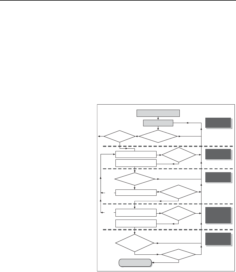
Following the National Research
Council’s 2005 report - Contam-
inants in the Subsurface - this
document is organized into four
sections (see adjacent figure
excluding the last element). The
first explores the nature of the
problem of chlorinated solvents in
subsurface environments. Fortun-
ately, through the investments of
Strategic Environmental Research
and Development Program
(SERDP) and ESTCP and others,
many of the key pieces of this
puzzle have come together in the
last few years. First, it is recoG-
nized that managing chlorinated
solvents often involves more than managing Dense Non-Aqueous Phase Liquids
(DNAPLs). Vapor, dissolved, and sorbed phase chlorinated solvents (particularly those
that occur in low permeability zones) often govern what can be achieved with current
remediation technologies. This has led to an emerging appreciation of the fact that there
are important differences in the ways in which various hydrogeologic settings store and
release contaminants, and that these settings control how sites evolve with time and
respond to remediation efforts.
The second section addresses developing objectives for sites. An emphasis is that
objectives need to be beneficial, attainable, and verifiable. An absence of any one of
the attributes diminishes the probability of success. Furthermore, they need to reflect the
needs and values of the involved parties. Consideration is given to absolute objectives
Are there
enough data to
determine functional
objectives?
Understanding
the Problem
Is there a source?
1b. Collect Data and
Refine SCM
2. Identify Absolute Objectives
3. Identify Functional Objectives
and Metrics
4. Identify Potential Technologies
5. Select among Technologies
and Refine Metrics
6. Design and Implement
Chosen Technology
Are there
enough data to
determine if a source
exists?
Developing
Objectives
Are there
enough data to select
potential tech-
nologies?
Is there
sufficient information
to resolve if the objectives
have been
achieved?
Resolving What
is Attainable
Have
objectives been
met?
Selecting
Remedies and
Performance
Metrics
DONE
Verifying
Desired
Performance
NO
NO
NO
NO
NO
YES
YES
YES
NO
YES
1a. Review Existing Site Data
and Preliminary SCM
YES
YES
YES
Are there
enough site-specific
data to choose among
technologies?
NO
YES
NO
Are
there enough
data to design and
implement the
remedy?
If there are
no viable
choices
If there are
no viable
choices

SECTION 1
A Guide for Selecting Remedies for Subsurface Releases of Chlorinated Solvents
3
that describe broad social goals and functional objectives that serve as a basis for
designing solutions. This section also reiterates the National Research Council’s
prescription for making remediation more successful: greater discipline in developing
goals and more evaluation of the probability of success prior to implementing a cleanup
project (NRC, 2005).
The third section provides an introduction to what we can expect from proven remediation
technologies. This section recognizes that the potential for success of any technology is
strongly dependent on the geologic setting and the end state that is trying to be achieved.
Emphasis is given to what technologies are likely to remove and what they are likely to
leave in place. Knowledge in this section builds on numerous SERDP and ESTCP
Reports addressing performance of remediation technologies.
Last, the topic of developing remedial packages for dealing with the challenge of
chlorinated solvent releases is addressed. This section recognizes that solutions require
not only the selection and implementation of specific technologies, but also a higher-
level, holistic view of sites and their challanges. Key factors that need to be considered
include subsequent land use, contingencies for variations from anticipated outcomes,
addressing the needs of all stakeholders, and maintaining realistic expectations regarding
what can be accomplished. Developing remedial packages is often a daunting task.
Common challenges include:
Differences in expectations from involved parties
The possibility of large uncertainty regarding subsurface conditions
The fact that the most common requirement for closure (near-term attainment of
drinking water standards (maximum concentration levels or MCLs) in
groundwater at all points) has rarely, if ever been achieved
The fact that finite funds are available, considering numerous social priorities.
The challenge of selecting and evaluating remedies is illustrated by a 2004 Navy Survey
You’ve go to be very
careful if you don’t
know where you are
going, because, you
might not get there.
Yogi Berra

SECTION 1
A Guide for Selecting Remedies for Subsurface Releases of Chlorinated Solvents
4
(Geosyntec, 2004). The Navy respondents indicated that the remedies were perceived to
be a “success” or “fair success” at 55 of 56 evaluated sites. At the same time, the survey
authors reported that “none of the remediation attempts presented in this survey/review
achieved MCLs or regulatory site closure.” The authors pointed out that achieving MCLs
was not always the reason for performing the remediation project, and that “other tangible
and intangible criteria … are used to interpret success.”
The dichotomy between perceived success and the lack of absolute success (restoring
groundwater to drinking water conditions) is explained by initial goals such as meeting
the planned expenditure, advancing new technology, meeting regulatory expectations,
and doing the best that one can. In regards to these objectives, the decision-makers
were often successful. On the other hand, endpoints that provide closure and/or
dramatically reduce the cost of long-term site care are (in the authors’ experience) rare.
Our philosophy in this decision guide and the companion FAQ document is not to be
prescriptive. How decisions are made and the values employed in selecting remedies
need to be tailored to the needs of the stakeholders. In addition, a primary theme in this
document is pragmatism, reflecting our perspective that the greatest progress can be
achieved by focusing on that which is beneficial and attainable.
In summary, the information presented herein is intended to assist decision-makers with
selecting remedies for releases of chlorinated solvents to the subsurface environment.
Content includes a review of the nature of the problem, consideration of the critical
components of setting objectives, a current overview of available options, and
suggestions for developing comprehensive remedial packages. Collectively, the goal is
to have a high frequency of success with chlorinated solvent sites, with the benefits of a
cleaner environment and the opportunity for DoD and others to better focus on their core
missions.
"A pragmatist turns towards concreteness
and adequacy, towards facts, towards
action and towards power"
William James
“The high ground lies in the middle”
R. Allan Freeze, The Environmental Pendulum

SECTION 2
A Guide for Selecting Remedies for Subsurface Releases of Chlorinated Solvents
5
Section 2 - Understanding the Problem
1
The following section describes the behavior of chlorinated solvents in subsurface
environments. As shown in the adjacent image (adapted from NRC 2005), having a
clear and holistic understanding of the problem is the first step in advancing a sound
solution at solvent sites.
To start, this section describes
processes governing the movement and
distribution of chlorinated solvents in
subsurface environments. It describes
the mechanisms of contaminant storage,
release, and transport in source and
plumes. Furthermore, it provides an
introduction to the 14 Compartment
Model, a new and powerful graphic
decision tool that is a cornerstone of this
document.
Next, critical attributes of common
geologic settings are identified. Building
on work by the National Research
Council (NRC, 2005), five hydrogeologic “type settings” are advanced. Each of these
type settings has potentially unique mechanisms for storing chlorinated solvents and
responses to remedial actions. Emphasis is given to the fact that the nature of the
problem in each setting evolves with time and involves early, middle and late stages.
1
The following section of this report was written for this document Subsequently, with permission from ESTCP and
Springer Publlishing it was edited and published as Chapter 7 In Situ Remediation of Chlorinated Solvent Plumes,
Editors H. Ward and H. Stroo, Springer, New York, pp.85-117
Are there
enough data to
determine functional
objectives?
Understanding
the Problem
Is there a source?
1b. Collect Data and
Refine SCM
2. Identify Absolute Objectives
3. Identify Functional Objectives
and Metrics
4. Identify Potential Technologies
5. Select among Technologies
and Refine Metrics
6. Design and Implement
Chosen Technology
Are there
enough data to
determine if a source
exists?
Developing
Objectives
Are there
enough data to select
potential tech-
nologies?
Is there
sufficient information
to resolve if the objectives
have been
achieved?
Resolving What
is Attainable
Have
objectives been
met?
Selecting
Remedies and
Performance
Metrics
DONE
Verifying
Desired
Performance
NO
NO
NO
NO
NO
YES
YES
YES
NO
YES
1a. Review Existing Site Data
and Preliminary SCM
YES
YES
YES
Are there
enough site-specific
data to choose among
technologies?
NO
YES
NO
Are
there enough
data to design and
implement the
remedy?
If there are
no viable
choices
If there are
no viable
choices

SECTION 2
A Guide for Selecting Remedies for Subsurface Releases of Chlorinated Solvents
6
Last, the current state of knowledge regarding how source control measures affect
contaminant concentrations in downgradient plumes is reviewed. Given that plumes
represent a primary exposure pathway, this is a critical concern.
Processes Governing the Movement and Distribution of
Chlorinated Solvents in Subsurface Environments
This section presents an overview of processes governing the movement and distribution
of chlorinated solvents in source zones and plumes. As a first step, it is critical to
recognize that chlorinated solvents in subsurface environments occur in four different
phases:
A gas phase in soil vapor
Dense Nonaqueous Phase Liquid (DNAPL)
A dissolved phase in water
A sorbed phase on aquifer solids
Second, it is essential to recognize that each phase can exist in either transmissive or
low permeability geologic media present in source zones and plumes. Distinguishing
between transmissive and low permeability zones is extremely important because
contaminants in transmissive zones are found in moving groundwater, while
contaminated groundwater in a low permeability zone is largely stagnant. Payne et al.
(2008) advances this conceptualization by describing aquifers as bodies containing
mobile and immobile pore space. Understanding the mass transfer of chlorinated
solvents between transmissive zones (mobile pore space) and low permeability zones
(effectively immobile pore space) is essential to understanding the remediation of
chlorinated solvent releases.
Building on the four phases, the important distinction between transmissive and low
permeability zones, and source and plume, Table 1 delineates 14 compartments in which
chlorinated solvents occur. A key attribute of the system of 14 compartments is that it
provides a new and holistic view of the problem of chlorinated solvents in subsurface
environments that blends hydrogeology, contaminant phases, and location.

SECTION 2
A Guide for Selecting Remedies for Subsurface Releases of Chlorinated Solvents
7
Table 1 – 14 subsurface compartments potentially containing chlorinated solvents.
Arrows show mass potential transfer links between compartments. Dashed arrows
indicate irreversible fluxes.
Source Zone Plume
Phase/Zone
Low
Permeability
Transmissive
Transmissive
Low
Permeability
Vapor
DNAPL
NA NA
Aqueous
Sorbed
NA – As per the definition of source zones in NRC (2006), DNAPLs are only
present in sources zones and consequently are absent in plumes.
Referred to as “The 14 Compartment Model,” Table 1 is used as a conceptual tool
through the remainder of this document. A simple example of the utility of the 14
Compartment Model comes through consideration of a remedy involving extraction of
groundwater (pump and treat) from the body in which DNAPL was released (a source
zone). The primary effect of pump and treat is to deplete aqueous phase solvents in
transmissive zones. A secondary effect is the slow release of solvents stored in other
impacted compartments (e.g., DNAPL in transmissive zones and/or dissolved and sorbed
chlorinated solvents in low permeability zones). These processes are described in detail
in Section 4 of this document. Unfortunately, slow release of solvents from compartments
that are not directly addressed can create a need to extract groundwater from source
zones for decades or even centuries. The remainder of this section addresses key
attributes of chlorinated solvent releases by describing the four phases of concern.
It is important to realize that the 14 Compartment Model is a useful tool, but it is only part
of a conceptual site model. Explicitly considering the 14 Compartment Model helps
ensure that all of the different phases and transmissive zones are considered when
making management decisions. But it is also important that a conceptual site model
include a mass balance that addresses the spatial distribution of the mass of
contaminants, and the fluxes of contaminants within the site, as well as the hydrogelogic
and biogeochemical information needed to evaluate fate and transport. The use of the

SECTION 2
A Guide for Selecting Remedies for Subsurface Releases of Chlorinated Solvents
8
14 Compartment Model is designed to encourage the development of integrated
strategies, in conjunction with the other aspects of a quantitative conceptual site model.
DNAPL
Subsurface environments consist of solids (e.g., soil, grains, or rock) and void space (soil
pores or fracture apertures). The void space contains water above and below the water
table. In the unsaturated zone, air coexists with pore water. Compared to air, water is
preferentially attracted to solids and forms a continuous “wetting phase” that covers the
matrix solids and fills the smaller pore spaces. In larger pores, water tends to occupy
margins, leaving the remaining central portions filled with air, present as a “non-wetting
phase.” Figure 1 shows porous media that contains both wetting and non-wetting
phases. Recognizing the coexistence of multiple phases (e.g., water, air, and DNAPL),
which can be closely commingled in tiny pores, is a key element of understanding mass
transfer between phases.
Figure 1 - Immiscible fluids in the pore space of a
granular porous media (after Wilson et al., 1990)
Driven by gravity and capillary forces, DNAPL released at the surface migrates
downward through the subsurface. Capillary forces reflect the tendency of wetting fluids
to be drawn into porous media due to liquid-liquid attraction or liquid-solid attraction (e.g.,
water being drawn into a dry sponge). Above the capillary fringe, DNAPL displaces air
and typically occurs as an intermediate wetting phase between water and air. Over time,
volatile DNAPL components partition into soil gas. This produces vapor plumes near

SECTION 2
A Guide for Selecting Remedies for Subsurface Releases of Chlorinated Solvents
9
releases. Given a sufficiently large release, DNAPL will migrate into and below the water
table. In the groundwater zone, DNAPL displaces water and occurs (typically) as a non-
wetting phase. With time, soluble constituents in DNAPL partition into groundwater,
forming aqueous plumes in transmissive zones downgradient of the DNAPL zone. An
interesting aspect of this process is that the formation of plumes comes with depletion of
DNAPL and, ultimately, all of the DNAPL will be depleted.
The occurrence of chlorinated solvents as an immiscible non-wetting phase in the
saturated zone influences the movement and ultimate distribution of DNAPL. For DNAPL
to invade water-saturated media, it must displace the water. This requires that pressure
in the DNAPL be greater than the water pressure by an amount known as the
displacement pressure (Corey 1994). For a given DNAPL, the displacement pressure is
related to the size of the pore. For larger pores the displacement pressure for DNAPL is
low, and conversely, for small pores the DNAPL displacement pressure is high.
Given the heterogeneous nature of geologic media and the mechanics of multiphase
flow, DNAPL in the saturated zone preferentially invades intervals with the largest pores.
Conceptually, this leads to sparse DNAPL bodies described as pools (horizontal
subzones) and fingers (interconnecting vertical tubes) that occupy only a small volume of
the available pore space. This conceptualization is based on field experiments (e.g.,
Poulson and Kueper, 1992; Kueper et al., 1993) and theoretical developments (e.g.,
McWhorter and Kueper, 1996).
Initially, the fraction of pore space filled with DNAPL (pore saturation) is large enough that
the DNAPL bodies are continuous (i.e., there are interconnected DNAPL-filled pores).
Over time, the DNAPL is depleted through drainage, dissolution, and/or volatilization.
These processes reduce DNAPL saturations and transform the continuous DNAPL flow
paths into discontinuous ganglia and blobs (Wilson et al., 1990). DNAPL ganglia and
blobs are largely immobile as separate phase liquids. Eventually, all of the DNAPL will
be transferred to dissolved, vapor, and sorbed phases. Given all of this, the nature of the
problems associated with chlorinated solvent releases changes with time.
The architecture of DNAPL pools and fingers within the subsurface is dependent on
numerous factors including geology, the rate at which the DNAPL was released, the
volume of the release, and the age of the release (Feenstra et al., 1996). Figure 2 (from
Feenstra et al., 1996) illustrates four conceptual DNAPL architectures in alluvium,
containing both granular and fractured media. The presence of a low permeability layer
plays a primary role in defining where the pools occur. DNAPL tends to perch above any

SECTION 2
A Guide for Selecting Remedies for Subsurface Releases of Chlorinated Solvents
10
low permeability capillary barrier. In general, rapid releases are thought to create more
horizontal spreading while slower releases create less horizontal spreading (Feenstra et
al., 1996). Last, DNAPL in fingers is likely to be depleted far more quickly than DNAPL in
pools because the geometry and orientation to groundwater flow of DNAPL in ganglia
creates a relatively large surface area exposed to flushing (Sale and McWhorter, 2001).
Therefore, DNAPL in fingers may be present only during the early stages of a release.
Figure 2 – Examples of DNAPL architecture (Feenstra et al., 1996).
In more detail, Figure 2 Panel “a” represents DNAPL in a fractured clay system, where
DNAPL is present in a network of natural fractures in the clay. Panel “b” represents the
same conditions as panel “a”, but with enough DNAPL released to penetrate into
underlying clay, forming fingers and pools. Panel “c” shows a complex site, where a
sand unit with DNAPL is underlain by what would be considered an aquitard, but in this
case is fractured to the extent that DNAPL penetrates into the next deepest sand layer.
Panel “d” shows complex vertical and lateral movement of DNAPL due to unfractured
low-permeability zones. The distribution of DNAPL is controlled by the hydrogeology and
the release characteristics of each example site.
Critically absent in Figure 2 are rigorous representations of vapor plumes, groundwater
plumes, and solvents sorbed onto aquifer solids. Note that DNAPL is just one of the four
phases that can sustain contamination in groundwater and vapor plumes, and more
importantly, the distribution between the four phases will change over time as the source
ages.

SECTION 2
A Guide for Selecting Remedies for Subsurface Releases of Chlorinated Solvents
11
Vapor Phase
Vapor phase chlorinated solvents originate from direct volatilization of DNAPL in the
unsaturated zone or from volatilization of aqueous phase chlorinated solvents in pore
water to air in the subsurface. Critically, chlorinated solvents are also present as a
sorbed phase on solids. Given close commingling of fluids (millimeter or less) chlorinated
solvents readily partition between each of the phases.
Under natural conditions, the primary transport process for vapor phase chlorinated
solvents is gas phase diffusion. This reflects the volatility of chlorinated solvents and
large gas phase diffusion coefficients (potentially four orders of magnitude greater than
aqueous phase diffusion coefficients). At any point in a porous media, the effective
diffusion coefficient is strongly dependent on water content. As water content increases,
the cross-sectional area available for vapor phase transport decreases and the tortuosity
of the flow paths increase. Higher water content leads to a reduced effective diffusion
coefficient.
Transport of vapor phase chlorinated solvents also occurs via advection of the vapor
phase. Advection can be driven by volatilization of DNAPL, changes in atmospheric
pressure, engineered systems (e.g., soil vapor extraction) and negative pressure in
buildings.
As chlorinated solvent vapor plumes expand, contaminants partition into pore water and
adsorb onto the matrix solids. Initially, this process retards the expansion of vapor
Per Cohen and Mercer (1993), the total mass of
solvents in a volume of porous media is the sum of
the nonaqueous, aqueous, vapor, and sorbed phases.
At any point in space each of the phases is trying to
equilibrate with the other phases.
sorbedvaporaqueousDNAPLTotal
ω
ω
ω
ω
ω
+++=
where
ω
is the mass of contaminant (e.g., chlorinated
solvent) per unit mass porous media.

SECTION 2
A Guide for Selecting Remedies for Subsurface Releases of Chlorinated Solvents
12
plumes. At later times, chlorinated solvents stored in pore water and sorbed to solids can
sustain vapor plumes. Degradation of parent chlorinated solvents in unsaturated zones
via biologically mediated processes may not be an important consideration at most sites
due to presumed aerobic conditions in most unsaturated zones away from source zones
(although recent research indicates limited degradation may be occurring at many sites).
Important exceptions are degradation products such as vinyl chloride, dichloroethene,
and methylene chloride, which readily degrade under aerobic conditions in vapor plumes.
Vapor plumes present two primary challenges. First, they can contaminate underlying
groundwater via diffusion and/or percolation of soil water through the unsaturated zone.
Second, vapor plumes can adversely impact indoor air quality. Both of these conditions
are common drivers for remedial actions.
Aqueous Phase
As soon as DNAPL encounters water in the subsurface, constituents in the DNAPL begin
to partition into water they share pore space with. In both saturated and unsaturated
zones, mass transfer occurs between phases in small pore spaces where solids, water
and DNAPL are closely commingled. Dissolution of DNAPL constituents into water is
driven by differences in the constituents’ chemical potential between the DNAPL phase
and water phase (Schwarzenbach et al., 1993). Once the chemical potentials in the
separate phases equilibrate, the constituents in the aqueous phase reach their effective
solubility. Effective solubility is primarily a function of the compound’s pure phase
solubility and its mole fraction in the DNAPL (Feenstra et al., 1996).
Over time, advection, dispersion, diffusion, and degradation drive dissolved constituents
away from DNAPL zones. This depletes aqueous phase chlorinated solvents at the
water-DNAPL interfaces and allows for further dissolution of DNAPL. Ultimately, the rate
of DNAPL dissolution is governed either by the local rate at which constituents can
partition into groundwater (Miller et al., 1990; Powers et al., 1991, or by the rate at which
dissolved phase constituents migrate away from the DNAPL (Sale and McWhorter,
2001).
Within transmissive portions of the saturated zone, advective transport produces
groundwater plumes that can extend over large distances, for as much as several miles
in some cases. As plumes advance, dissolved phase solvents are lost through sorption,
diffusion into low permeability layers, and degradation. At some sites, natural rates of

SECTION 2
A Guide for Selecting Remedies for Subsurface Releases of Chlorinated Solvents
13
attenuation are rapid enough to create stable or even shrinking plumes (Wiedemeier et
al., 1999), and risks to receptors can be addressed through natural processes.
Unfortunately, natural attenuation alone is often insufficient to address potential adverse
impacts of chlorinated solvent releases.
Dissolved phase constituents also migrate into low permeability zones such as clay
lenses and aquitards. Note that with the exception of secondary permeability features
(e.g., fractures, root holes, animal burrows), high displacement pressures typically
preclude DNAPL from low permeability layers. Dissolved phase constituents, however,
can permeate low permeability zones through a combination of diffusion and slow
advection. Within low permeability zones, chlorinated solvents are present in both
dissolved and sorbed phases. Often, fine-grained low permeability zones have higher
sorption capacities due to their greater organic carbon contents and higher surface area
per unit volume than adjacent transmissive zones comprised of sands and/or gravels.
Higher organic carbon content increases the contaminant storage capacity of low
permeability layers and accelerates the diffusion of chlorinated solvents into the low
permeability materials (e.g., Parker et al, 1994 and Sale et al, 2008).
As long as the concentration of aqueous phase solvents is greater in the transmissive
zones than in the low permeability zone, solvents will be driven into the low permeability
zones. This matrix storage can be an important mechanism for attenuation of solvents in
plumes. However, once the aqueous concentration of the solvents declines in the
transmissive layer(s), solvents will begin diffusing back out of the low permeability layers.
This process, back diffusion, can sustain plumes for long periods of time (e.g., Liu and
Ball, 2002; Chapman and Parker, 2005; AFCEE, 2007; and Sale et al. 2008). Because
back diffusion is far slower than the initial inward diffusion process (Parker et al. 1996), it
can sustain plumes for extended periods even after all DNAPL is depleted (Figure 3).

SECTION 2
A Guide for Selecting Remedies for Subsurface Releases of Chlorinated Solvents
14
Degradation of Chlorinated Solvents
For many years the prevailing opinion was that aqueous phase chlorinated solvents
did not degrade under natural conditions in aquifers. However, in the 1980s several
researchers (e.g., Vogel and McCarty, 1985; Wilson and Wilson, 1985)
demonstrated that biotic processes could degrade chlorinated solvents under
reducing (i.e., anaerobic) conditions. This discovery was largely responsible for the
acceptance of natural attenuation as a plume management strategy in the late
1990s (Wiedemeier et al., 1998; 1999).
In addition, research conducted in the 1990s indicated that chlorinated solvents can
be degraded abiotically via chemical oxidation (Farquar et al., 1991) and chemical
reduction (Gillham and O`Hannesin, 1994). More recently it has been recognized
that naturally occurring minerals (e.g., magnetite) can also drive abiotic reduction of
chlorinated solvents (Danielsen and Hayes, 2004).
The table below identifies the average carbon oxidation state in common chlorinated
solvents and associated degradation products. In general, chlorinated solvents with
large oxidation states (CT>PCE, CF>TCE) are prone to degradation via reduction.
Conversely, chlorinated solvents with lower oxidation states (CM<DCA, VC<DCE,
TCA, MC) are prone to degradation via oxidation.
PCE
TCE
DCE
Vinyl Chloride VC
TCA
DCA
CT
CF
MC
Chloromethane
CM
Carbon Oxidation
States
4
3
2
1
-3
-1
0
-2
-4
Ethenes Ethanes Methanes
Methane
Ethene
Ethane
Oxidized
Reduced
PCA

SECTION 2
A Guide for Selecting Remedies for Subsurface Releases of Chlorinated Solvents
15
Figure 3 - Diffusion into and out of low permeability materials,
leading to initial plume attenuation and subsequent long-term
plume persistence (After AFCEE, 2007).
Matrix diffusion and back diffusion have received broad attention. Foster (1975), Tang et
al. (1981), Sudicky et al. (1993), and Parker et al. (1996) address diffusion within granular
fractured porous media. Freeze and Cherry (1979), Rao et al. (1980), Sudicky (1983),
Sudicky et al. (1985), Goltz and Roberts (1987), Wilson (1997), Liu and Ball (2002),
Chapman and Parker (2005), AFCEE (2007) and Sale et al. (2008) address diffusion in
heterogeneous unfractured granular porous media. The most recent of these
publications (Wilson, 1997; Liu and Ball, 2002; Parker and Chapman, 2005; AFCEE,
2007 and Sale et al., 2008), specifically recognize that these processes can impact our
ability to restore groundwater quality in source zones and in plumes.

SECTION 2
A Guide for Selecting Remedies for Subsurface Releases of Chlorinated Solvents
16
Source strength before and after complete DNAPL dissolution
The following experiment illustrates the dissolution of DNAPL into aqueous phases in a
two-layer system (Wilkins, 2005 and AFCEE, 2007). Two layers with an approximate 2
order of magnitude contrast in permeability are present in the sand tank. Water is
flushed through the upper transmissive sand layer at a seepage velocity of 1.5 ft/day.
A 15-gram pool of 1,1,2-TCA is introduced in the transmissive sand immediately above
the low permeability layer.
56cm
45 cm
#30 Sand
#140 sand
1,1,2-TCA DNAPL
Pool 2.5 x 10 cm
18 cm
Groundwater
Flow 1.5 ft/day
56cm
45 cm
#30 Sand
#140 sand
1,1,2-TCA DNAPL
Pool 2.5 x 10 cm
18 cm
Groundwater
Flow 1.5 ft/day
Key results are presented below. The boxes in the graph reflect the amount of
DNAPL remaining in the tank as a function of time. This was determined by measuring
absorbance of a scanning x-ray source. Results show that the DNAPL completely
dissolves in 5.5 days. The triangles depict cumulative aqueous phase discharge of
1,1,2-TCA from the tank. This is based on effluent concentrations and the flow rate
through the tank. By the time the DNAPL is fully dissolved, 10 grams of TCA have
been discharged from the tank via the transmissive layer. The majority of the
remaining 5 grams has been driven into the low permeability layer via transverse
diffusion (data posted as X’s). Sustained discharge of aqueous phase TCA from the
tank after DNAPL depletion (triangles) reflects back diffusion of aqueous phase TCA
from the low permeability layer. An interesting observation is that the overall rates of
contaminant discharge from the tank are similar with and without DNAPL.
Distribution of TCA Mass Recovered vs. Time
0
2,000
4,000
6,000
8,000
10,000
12,000
14,000
012345678910
Elapsed Time (Days)
Cumulative TCA (mg)
Cumulative TCA Mass Recovered
Remaining Mass from xray
TCA Mass in Tank Outside Source Zone
Distribution of TCA Mass Recovered vs. Time

SECTION 2
A Guide for Selecting Remedies for Subsurface Releases of Chlorinated Solvents
17
Sorbed Phase
The sorbed phase is the contaminant mass that resides in or on the matrix solids. This
fraction of the total mass includes both contaminant adsorption onto solid surfaces and
absorption of contaminants into the matrix particles. As the aqueous phase
concentrations increase, there is a net transfer of contaminants to the sorbed phase.
This equilibrium partitioning attenuates and slows the migration of dissolved phase
contaminant concentration as the plumes advance by removing dissolved contaminants
from the transmissive zone. In addition, it creates an in situ reservoir of immobile stored
contaminants. The initial process of attenuating aqueous phase contamination via
sorption is referred to as retardation.
Experiment Illustrating Contaminant Storage and Release from Low
Permeability Layers
The images below show studies in which water containing fluorescein dye was
flushed through a tank containing sand and clay layers (Doner, 2007). Initially the
fluorescein is attenuated via diffusion into the clay layers (Panel B). Continued
flushing without the fluorescein illustrates how back diffusion from the low
permeability clay can sustain contaminant levels in a plume occurring in a
transmissive zone in the absence of an upgradient source (Panels C and D).
Panel A - Sand and Clay Panel B - Fluorescein Inflow (Matrix Storage)
Panel C - Source Off – Back Diffusion Panel D- Close-up of Back Diffusion
50 cm
Panel A - Sand and Clay Panel B - Fluorescein Inflow (Matrix Storage)
Panel C - Source Off – Back Diffusion Panel D- Close-up of Back Diffusion
50 cm

SECTION 2
A Guide for Selecting Remedies for Subsurface Releases of Chlorinated Solvents
18
Conversely, as aqueous phase concentrations decrease as the site ages (due to natural
weakening of the source or active source remediation), contaminants are released from
the sorbed phase back into the aqueous phase. This desorption has the net effect of
sustaining the aqueous phase concentrations. As a first order approximation, the amount
of sorbed contamination is proportional to the fraction of organic carbon (f
oc
) present in
the porous media and the compound’s organic carbon partitioning coefficient (K
oc
),
Greater detail is provided in Karickhoff et al. (1979) and Schwarzenbach et al. (1993).
To illustrate the relative distribution of the aqueous and sorbed phase contaminant mass,
Figure
4 plots the contaminant fraction present in the aqueous and sorbed phases, given
a typical range of f
oc
values. At a high organic carbon content (f
oc
>0.01), more than 90
percent of the contaminant mass is present as a sorbed phase. Given high surface areas
and deposition in quiescent environments, this is a plausible scenario for silts or clay
deposited in an organically rich environment. At the low end of the range of organic
carbon contents (foc < 0.001), only 10 to 20 percent of the total contaminant mass may
be stored in the sorbed phase.
1
.
10
4
1
.
10
3
0.01
0
0.2
0.4
0.6
0.8
1
PCE
TCE
CT
1,1,1-TCA
Fraction of Organic Carbon
Contaminant Fraction in the Aqueous Phase
1
.
10
4
1
.
10
3
0.01
0
0.2
0.4
0.6
0.8
1
Fraction of Organic Carbon
Contaminant Fraction in Sorbed Phase
Figure 4 – Fractions of total contaminant mass in the aqueous and sorbed phases
as a function of the fraction of organic carbon (Following Schwarzenbach et al.
(1993), using parameters for typical saturated soils and K
oc
values from Allen-King
et al. (1996)).

SECTION 2
A Guide for Selecting Remedies for Subsurface Releases of Chlorinated Solvents
19
More recently, several researchers have determined that sorption and desorption have a
linear relationship only at higher concentrations, and at lower concentrations a hysteretic
effect is observed due to availability effects (e.g., Pignatello and Xing, 1996). Some
researchers call this hysteresis effect “dual-equilibrium desorption” (Chen et al., 2004).
Like matrix diffusion, desorption can sustain low-concentration groundwater plumes for
long periods of time.
Critical Attributes of Common Geologic Settings
As stated in NRC (2005), “Subsurface settings are a product of a set of diverse geologic
processes that produce an abundance of variation.” These “geologic variations” play a
primary role in controlling the distribution of chlorinated solvents in subsurface
environments, and are critical to understanding of how chlorinated solvent releases
evolve with time. Geologic variations also control the effectiveness of remedial actions.
The following a) introduces five geologic “type settings” and b) contemplates how solvent
releases in each type setting will evolve with time.
Geologic Type Settings
NRC (2005) describes five general geologic type settings (Figure 5). In the interest of
consistency, the portions of the following text in italics are direct quotes from NRC (2005).
(I) Granular Media with Mild Heterogeneity and
Moderate to High Permeability
(
e.g. eolian sands)
(III) Granular Media With Moderate to
High Heterogeneity
(e.g. deltaic deposition)
(IV) Fracture Media with Low Matrix
Porosity
(e.g.crystalline rock)
(V) Fracture Media with High Matrix
Porosity
(e.g.limestone, sandstone
or fractured clays)
(II) Granular Media with Mild Heterogeneity
and Low Permeability
(
e.g. lacustrine clay)
Figure 5 – Geologic Type Settings (NRC 2005)

SECTION 2
A Guide for Selecting Remedies for Subsurface Releases of Chlorinated Solvents
20
Type I – Granular Media with Mild
Heterogeneity and Moderate to High Permeability
Type I media include systems with porosities that are consistent with typical granular
media (e.g., 5 percent to 40 percent), permeability values that are consistent with sand or
gravel deposits (>10
-14
m2 or hydraulic conductivity >10
-7
m/s), and mild heterogeneity
(less than three orders of magnitude). As conceptualized, this material is about as
uniform as it can be in nature and thus is relatively uncommon. Deposits of this nature
are encountered in association with windblown sands and beach deposits. Examples
include beach sands at the Canadian Forces Base Borden, Canada, and dune deposits
at Great Sand Dunes National Park, Colorado ( Figure 6).
Figure 6 - Examples of Type I media (Great Sand Dunes National Park web site)
Due to mild heterogeneity and moderate to high permeability, stagnant zones are not
dominant in Type I settings and there is little contaminant storage in low permeability
layers (sorbed or dissolved). The dominant storage/release mechanism will be
associated with DNAPL dissolution and solid-phase sorption.
Type I settings are relatively rare. On the other hand, they have been widely represented
in laboratory experiments using columns or tanks (e.g., Schwille, 1988). As such, they
provide a viewpoint for our conceptualization of chlorinated solvents in subsurface
environments. However, the predominance of research studies conducted in Type 1
settings have led to an underappreciation of the importance of heterogeneity in other
geologic settings.

SECTION 2
A Guide for Selecting Remedies for Subsurface Releases of Chlorinated Solvents
21
Type II – Granular Media with Low
Heterogeneity and Low Permeability
Type II settings have porosities that are consistent with typical granular media (e.g., 5
percent to 40 percent), low spatial variation in permeability (less than three orders of
magnitude), low permeability consistent with silt or clay deposits (k < 10
-14
m2), and low
hydraulic conductivity (K < 10
-7
m/s). An example is a clay deposit with no significant
secondary permeability features (such as fractures, root holes, animal burrows). These
systems are uncommon (especially in the near-surface environment where releases
typically occur), although some examples include TCE-contaminated clays at the
Department of Energy’s Savannah River Site in South Carolina. More typically, low-
permeability materials contain significant secondary permeability features and thus fit
better into the Type V setting description (see below).
In Type II settings the entire zone can be viewed as hydraulically stagnant. The primary
contaminant transport process is diffusion. Settings of this nature are difficult to
contaminate, and as such, they are not a common concern for remediation efforts.
Type III – Granular Media with Moderate to High Heterogeneity
Type III settings encompass systems with moderate to large variations in permeability
(greater than three orders of magnitude) and porosities that are consistent with granular
media (e.g., 5 percent to 40 percent). Given large spatial variations in permeability (at
the scale of centimeters to meters), portions of the zone are comparatively transmissive
while others contain mostly stagnant fluids. As an example, an interbedded sandstone
and shale is shown in Figure 7. For the purpose of this report, the more transmissive
zones in Type III media have a permeability greater than 10
-14
m
2
(K > 10
-7
m/s). Near-
surface deposits of this nature are common due to the abundance of alluvium with large
spatial variations in permeability and are encountered in either rock or alluvium
associated with deltaic, fluvial, alluvial fan, and glacial deposits. Examples include the
Garber-Wellington Aquifer in central Oklahoma, the Chicot Aquifer in Texas and
Louisiana, and varved sediments near Searchmont, Ontario.

SECTION 2
A Guide for Selecting Remedies for Subsurface Releases of Chlorinated Solvents
22
Figure 7 - Interbedded sandstone and shale, an example of Type III media.
Photo provided by Fred Payne – ARCADIS.
In Type III settings, heterogeneity introduces stagnant groundwater zones to the system.
These zones initially attenuate DNAPL constituents that partition into groundwater. After
the DNAPL is depleted, the stagnant zones sustain groundwater plumes in transmissive
zones. The depositional environments that create low permeability zones often favor
higher concentrations of organic carbon. As a result, low permeability layers may have
large sorptive capacities, increasing the potential for diffusion into these materials, and
enhancing their ability to sustain dissolved chemical plumes after the original chemical
source (DNAPL) has been depleted, contained, or remediated.
Type IV - Fractured Media with Low Matrix Porosity
Fractured media with low matrix porosity are common in crystalline rock including
granite, gneiss, and schist. Examples include bedrock in the Piedmont and Blue Ridge
Mountain region of the southeastern United States and plutonic cores of mountain ranges
in the western United States (see Figure 8 for an example). The primary transmissive
feature in Type IV settings is the secondary permeability caused by fractures, because
little to no void space exists in the unfractured matrix. The permeability of the unfractured
matrix is considered to be less than 10
-17
m
2
(K < 10
-10
m/s). However, the bulk
permeability of the media is dependent on the frequency, aperture size, and degree of
interconnection of the fractures, such that the anticipated range of bulk permeability
values is 10
-15
–10
-11
m
2
(K = 10
-8
–10
-4
m/s). The porosity of both the matrix and the
fractures is typically small—less than 1 percent. However, in regions where crystalline

SECTION 2
A Guide for Selecting Remedies for Subsurface Releases of Chlorinated Solvents
23
rock has been extensively weathered (e.g., at the top of bedrock), the bulk media can
behave more like a porous medium than what would be expected from a fractured rock
type setting.
In Type IV settings, contaminant transport is primarily limited to fractures and there is little
mass storage in low permeability zones, due to low matrix porosity. The primary source
is likely DNAPL. Over time, DNAPL will be depleted from the more transmissive fractures
and DNAPL in low flow areas (e.g., dead end fractures) will dominate. Due to the
combined effects of low matrix attenuation and low fracture porosity, the contaminant
migration velocity at a fractured media site can be very rapid and, consequently, these
sites can have long plumes (Sudicky et al. 1993; Parker et al., 1996).
A primary challenge in this setting is the complexity of the fractures. The fracture
frequencies and their capacity to transmit fluid can be highly variable. Furthermore, the
degree to which sets of fractures are interconnected can also be highly variable.
Figure 8 - Fractured crystalline rock, an example of Type IV media
(Cache La Poudre River, Colorado, Photo provided by Tom Sale) .

SECTION 2
A Guide for Selecting Remedies for Subsurface Releases of Chlorinated Solvents
24
Type V – Fractured Media with High Matrix Porosity
This setting includes systems where fractures (secondary permeability) are the primary
transmissive feature and there is large void space in the matrix. The permeability of the
unfractured matrix is considered to be less than 10
-17
m
2
(K < 10
-10
m/s). The anticipated
range of bulk permeability values is 10
-16
–10
-13
m
2
(K = 10
-9
–10
-6
m/s). The porosity of
the fractures relative to the total unit volume is small (e.g., <1 percent). However, unlike
Type IV, in Type V hydrogeologic settings the porosity of the unfractured matrix is
anticipated to fall in the range of 1 to 40 percent. Fractured media with high matrix
porosity are commonly encountered in sedimentary rock (e.g., limestone, dolomite, shale,
and sandstone) and fractured clays. Examples include the Niagara Escarpment in the
vicinity of the Great Lakes (see Figure 2-7) and fractured lake-deposited (lacustrine)
clays in Sarnia, Ontario, Canada.
Figure 9 - Bedding planes, joints, and vertical fractures in carbonate rock,
Ontario, Canada (Photo Courtesy of Dr. Beth Parker University of Guelph).
Type V settings introduce stagnant zones to the system. These zones initially attenuate
DNAPL constituents that partition into groundwater by diffusion from the fracture zones
into the rock matrix. After the DNAPL is depleted, back diffusion sustains dissolved
phase concentrations in groundwater flowing in the fractures. For systems where the
matrix material has large sorptive capacities, the stagnant zones will act as a
contaminant sink and accelerate the rates of natural DNAPL depletion. Due to limited
mass storage in fractures, rapid depletion of DNAPL may occur via natural processes
(e.g., Parker et al. 1994).

SECTION 2
A Guide for Selecting Remedies for Subsurface Releases of Chlorinated Solvents
25
An important variant of the Type V setting is karst, which is common in carbonates (e.g.,
limestone or dolomite). In this scenario, transmissive zones include sinkholes, caves,
and other solution openings that vary widely in aperture and have the potential to store
and transport significant contaminant mass (see Figure 10). Permeability in karst terrains
varies over tens of orders of magnitude from low permeabilities between fractures to
open channel flow in channels and caves (Teutsch and Sauter, 1991; White, 1998;
White, 2002). Karst is characterized by both rapid transport along sparse dissolution
features and a high ratio of stagnant to transmissive zones. As such, it is one of the most
challenging hydrogeologic settings to characterize and manage.
Figure 10 - Large- and small-scale solution features in karst limestone, Redstone Arsenal
(Courtesy of Tom Zondlo, Shaw Engineering).
Source Zones Containing Multiple Type Settings
Source zones, especially those above a certain size, may encompass more than one
hydrogeologic setting. This commonly occurs in the instance of shallow alluvium over
bedrock. For example, in the Piedmont region of the southeastern United States, one
can find fluvial deposits (Type III) and saprolite (Type V)
overlying fractured crystalline
rock (Type IV). Selecting characterization tools and source management technologies is
challenging under these conditions, because although contamination may exist

SECTION 2
A Guide for Selecting Remedies for Subsurface Releases of Chlorinated Solvents
26
throughout, the appropriate tools for one hydrogeologic setting may not work in the
adjacent hydrogeologic setting.
Summary of Type Settings
Table 2 - provides a summary of the geologic type settings described in the prior text.
Table 2 – Summary of Geologic Type Settings
Geologic Setting
Permeability
(m
2
)
Hydraulic
Conductivity
(m/s)
Porosity
(%) Properties
Type I - Granular
Media with Mild
Heterogeneity and
Moderate to High
Permeability
k > 10
-14
K > 10
-7
5 – 40
- Uniform material
- Relatively
uncommon (e.g.,
sand or gravel
deposits)
Type II - Granular
Media with Low
Heterogeneity and
Low Permeability
k < 10
-14
K < 10
-7
5 - 40
- Low permeability
materials with no
secondary
permeability
features, i.e.,
fractures (e.g., clay
deposit)
Type III - Granular
Media with
Moderate to High
Heterogeneity
k > 10
-14
K > 10
-7
5 - 40
- Large spatial
variations in
permeability (e.g.,
deltaic, fluvial, and
glacial deposits)
Type IV - Fractured
Media with Low
Matrix Porosity
k < 10
-17
K < 10
-10
< 1 (both
fractures
and
matrix)
- Little void space
exists in
unfractured matrix
- Transmissive
features due to
fractures (e.g.,
crystalline rock)
Type V - Fractured
Media with High
Matrix Porosity
k < 10
-17
K < 10
-10
< 1
(fractures)
1 – 40
(matrix)
- Large void spaces
exist in unfractured
matrix
- Transmissive
features due to
fractures (e.g.,
limestone,
sandstone, and
clays with
secondary
permeability
features)

SECTION 2
A Guide for Selecting Remedies for Subsurface Releases of Chlorinated Solvents
27
Evolution of Chlorinated Solvent Releases as a Function of
Setting and Time
It is critical to recognize that chlorinated solvent sites evolve over time; in other words,
the location of the mass changes as the site ages. This occurs both with respect to the
spatial location of the vapor and dissolved phase plumes, but more importantly, with
respect to the distribution of the contaminant mass in the four phases. This process is
conceptualized in Figure 11 for a Type III setting (Granular Media with Moderate to High
Heterogeneity) underlain by a Type V setting (Fractured Media with High Matrix Porosity).
The adjacent image provides a key for the concentrations in each of the compartments.
In the initial stage, most of the contaminant
mass is found in the DNAPL phase, and this
DNAPL is the key problem. During the
middle stage, the problem has expanded to
all phases in transmissive and low
permeability zones in the source and the
plume. In the late stages, DNAPL is fully
depleted and the problem is dominated by
solvents stored in low permeability zones.
Building on the themes in Figure 11, Figure 12 illustrates the evolution of chlorinated
solvents in all five type settings. It is important to note that the described distributions are
plausible for each type setting but are not necessarily the only possibility. Other
distributions in the noted setting at the described stages are possible. For example,
vapor plumes may or may not be present depending on the release mechanism and/or
the depth to groundwater. The rate at which a DNAPL release matures is dependent on
numerous factors including the size of the release, the solubility/volatility of the DNAPL,
the hydrogeologic setting, and the local rate of groundwater flow.
1
2
3
4
0
Not impacted
1s of ug/L in water
10s of ug/L in water
100s of ug/L in water
> 1000s of ug/L in water
Concentrations in Aqueous Phase Equivalents

SECTION 2
A Guide for Selecting Remedies for Subsurface Releases of Chlorinated Solvents
28
Early Stage – The majority of the
release is present as a DNAPL.
Groundwater plumes are just
beginning to form and little if any
contamination is present in low
permeability zones.
Source Zone Plume
Zone/Phases Low
Permeability
Transmissive Transmissive Low
Permeability
Vapor 0 2 1 0
DNAPL 0 4
Aqueous 0 2 1 0
Sorbed 0 2 1 0
Middle Stage – Much of the original
DNAPL release (e.g., 50%) has moved
into vapor, aqueous, and/or sorbed
phases. Large vapor and/or
groundwater plumes may be present
and contaminants are present in low
permeability zones.
Source Zone Plume
Zone/Phases Low
Permeability
Transmissive Transmissive Low
Permeability
Vapor 2 2 2 2
DNAPL 2 3
Aqueous 2 3 3 2
Sorbed 2 3 3 2
Weathered – DNAPL is absent.
Plumes in transmissive zones can be
sustained by desorption and/or back
diffusion from low permeability layers
located in the source zone and plume.
Source Zone Plume
Zone/Phases Low
Permeability
Transmissive Transmissive Low
Permeability
Vapor 3 2 2 3
DNAPL 1 1
Aqueous 3 2 2 3
Sorbed 3 2 2 3
Figure 11 – Evolution of a chlorinated solvent release in a Type III setting as a function of
time. Red, yellow, and green compartments indicate high, moderate, and low importance of
the compartments, respectively. Noted conditions are plausible, but not necessarily the
only possibility.

SECTION 2
A Guide for Selecting Remedies for Subsurface Releases of Chlorinated Solvents
29
Source Zone Plume
Zone/Phases Low
Permeability
Transmissive Transmissive Low
Permeability
Vapor 2 1
DNAPL 3
Aqueous 2 1
Sorbed 2 1
Source Zone Plume
Zone/Phases Low
Permeability
Transmissive Transmissive Low
Permeability
Vapor 2 2
DNAPL 3
Aqueous 3 3
Sorbed 3 3
Source Zone Plume
Zone/Phases Low
Permeability
Transmissive Transmissive Low
Permeability
Vapor 2 2
DNAPL 0
Aqueous 2 3
Sorbed 2 3
Type I
Type II
Type III
Type IV
Type V
Early
Middle Late
Source Zone Plume
Zone/Phases Low
Permeability
Transmissive Transmissive Low
Permeability
Vapor 0 0
DNAPL 0
Aqueous 2 0
Sorbed 2 0
Source Zone Plume
Zone/Phases Low
Permeability
Transmissive Transmissive Low
Permeability
Vapor 0 0
DNAPL 0
Aqueous 3 2
Sorbed 3 2
Source Zone Plume
Zone/Phases Low
Permeability
Transmissive Transmissive Low
Permeability
Vapor 0 0
DNAPL 0
Aqueous 3 3
Sorbed 3 3
Source Zone Plume
Zone/Phases Low
Permeability
Transmissive Transmissive Low
Permeability
Vapor 0 2 1 0
DNAPL 0 4
Aqueous 0 2 1 0
Sorbed 0 2 1 0
Source Zone Plume
Zone/Phases Low
Permeability
Transmissive Transmissive Low
Permeability
Vapor 2 2 2 2
DNAPL 2 3
Aqueous 2 3 3 2
Sorbed 2 3 3 2
Source Zone Plume
Zone/Phases Low
Permeability
Transmissive Transmissive Low
Permeability
Vapor 3 2 2 3
DNAPL 1 1
Aqueous 3 2 2 3
Sorbed 3 2 2 3
Source Zone Plume
Zone/Phases Low
Permeability
Transmissive Transmissive Low
Permeability
Vapor 2 1
DNAPL 3
Aqueous 2 1
Sorbed 2 1
Source Zone Plume
Zone/Phases Low
Permeability
Transmissive Transmissive Low
Permeability
Vapor 2 2
DNAPL 3
Aqueous 3 3
Sorbed 3 3
Source Zone Plume
Zone/Phases Low
Permeability
Transmissive Transmissive Low
Permeability
Vapor 2 2
DNAPL 0
Aqueous 2 3
Sorbed 2 3
Source Zone Plume
Zone/Phases Low
Permeability
Transmissive Transmissive Low
Permeability
Vapor 0 2 1 0
DNAPL 0 4
Aqueous 0 2 1 0
Sorbed 0 2 1 0
Source Zone Plume
Zone/Phases Low
Permeability
Transmissive Transmissive Low
Permeability
Vapor 2 2 2 2
DNAPL 2 3
Aqueous 2 3 3 2
Sorbed 2 3 3 2
Source Zone Plume
Zone/Phases Low
Permeability
Transmissive Transmissive Low
Permeability
Vapor 3 2 2 3
DNAPL 1 1
Aqueous 3 2 2 3
Sorbed 3 2 2 3
Figure 12 – Illustration of plausible distributions of chlorinated solvent as a function of type setting and the stage of
release. Gray boxes are considered to be absent in the type setting. Red, yellow, and green compartments indicate
high, moderate, and low importance of the compartments, respectively. Note that conditions presented are plausible
in the noted situations, but not necessarily the only possible scenario
.
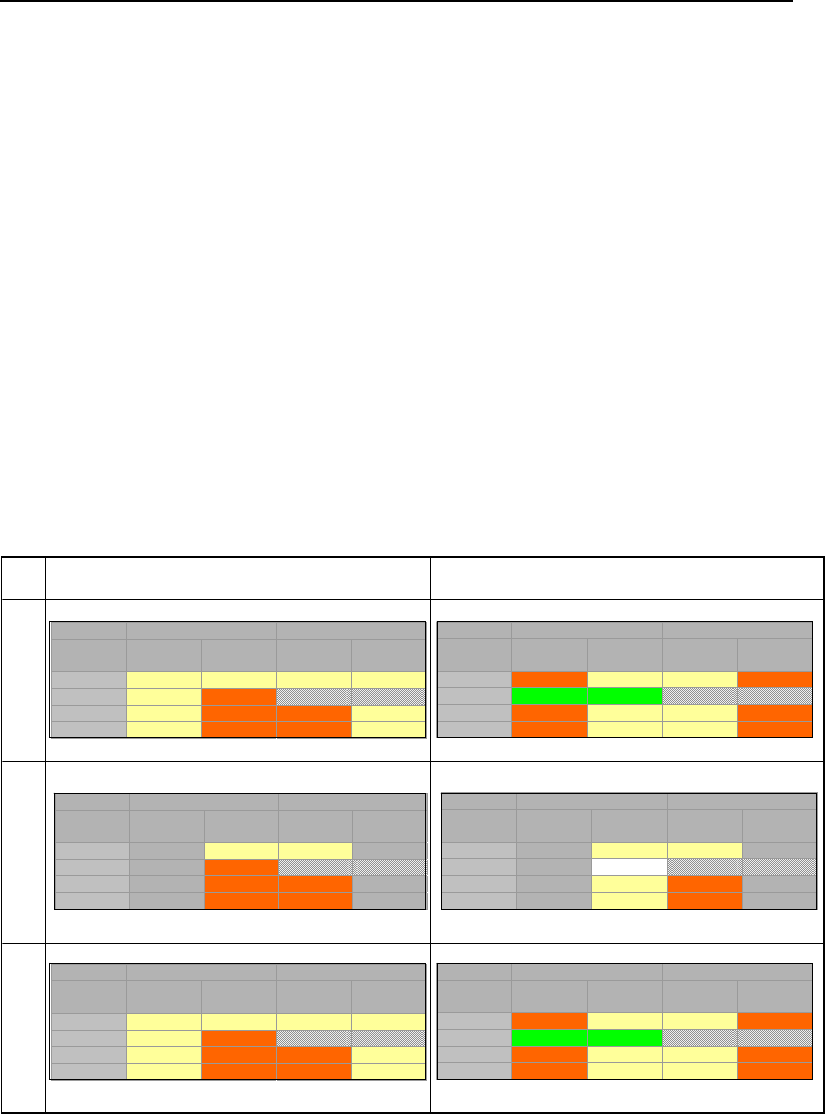
SECTION 2
A Guide for Selecting Remedies for Subsurface Releases of Chlorinated Solvents
30
Figure 12 can be simplified from 15 to 6 scenarios by recognizing that:
Type Settings I and II are relatively uncommon in natural settings. Even the well-
studied Canadian Forces Base Borden site, which is widely viewed as uniform
sand, has three orders of magnitude of spatial variation in hydraulic conductivity
(Sudicky, 1986) and is underlain by lacustrine clay. Contaminated Type II sites
are also relatively rare.
Overall, early stage sites are very rare. Most of the sites we currently deal with
are 30, 40, or even 50 years old.
Given the limited frequency of Type I settings, Type II settings, and early stage
conditions,
Figure
13 illustrates the 6 primary scenarios of concern for chlorinated solvent
releases.
Type III
Type IV
Type V
Middle Late
Source Zone Plume
Zone/Phases Low
Permeability
Transmissive Transmissive Low
Permeability
Vapor 2 2 2 2
DNAPL 2 3
Aqueous 2 3 3 2
Sorbed 2 3 3 2
Source Zone Plume
Zone/Phases Low
Permeability
Transmissive Transmissive Low
Permeability
Vapor 3 2 2 3
DNAPL 1 1
Aqueous 3 2 2 3
Sorbed 3 2 2 3
Source Zone Plume
Zone/Phases Low
Permeability
Transmissive Transmissive Low
Permeability
Vapor 2 2
DNAPL 3
Aqueous 3 3
Sorbed 3 3
Source Zone Plume
Zone/Phases Low
Permeability
Transmissive Transmissive Low
Permeability
Vapor 2 2
DNAPL 0
Aqueous 2 3
Sorbed 2 3
Source Zone Plume
Zone/Phases Low
Permeability
Transmissive Transmissive Low
Permeability
Vapor 2 2 2 2
DNAPL 2 3
Aqueous 2 3 3 2
Sorbed 2 3 3 2
Source Zone Plume
Zone/Phases Low
Permeability
Transmissive Transmissive Low
Permeability
Vapor 3 2 2 3
DNAPL 1 1
Aqueous 3 2 2 3
Sorbed 3 2 2 3
Figure 13 – Six primary scenarios of concern for chlorinated solvent releases.
At complex sites it may be difficult to develop a single Fourteen Compartment model that
describes conditions throughout an entire release. In these cases it may be useful to
divide a release into separate blocks, as shown in Figure
14.

SECTION 2
A Guide for Selecting Remedies for Subsurface Releases of Chlorinated Solvents
31
Type III vadose zone
Type III saturated alluvium
Type V saturated
fractured bedrock
with high matrix porosity
Source Zone Plume
Zone/Phases Low
Permeability
Transmissive Transmissive Low
Permeability
Vapor 2 3 2 2
DNAPL 1 1
Aqueous 2 3 2 2
Sorbed 2 3 2 2
Source Zone Plume
Zone/Phases Low
Permeability
Transmissive Transmissive Low
Permeability
Vapor
DNAPL 2 3
Aqueous 2 3 2 2
Sorbed 2 3 2 2
Source Zone Plume
Zone/Phases Low
Permeability
Transmissive Transmissive Low
Permeability
Vapor
DNAPL 1 2
Aqueous 2 2 2 2
Sorbed 2 2 2 2
Figure 14 – Use of multiple 14 Compartment Models to describe a complex site.
As noted in the introduction, the 14 Compartment Model drives a holistic view of
chlorinated solvents sites which is helpful for making informed decisions. But as was
also noted, there are limitations to the model, and a thorough conceptual site model is
still required. One potential limitation is that it can be difficult to develop reasonable
estimates for all of the compartments. This problem may be common, but it is better to be
forewarned than surprised. In the past we have been surprised too many times.
The model often points out the limitations of site characterizations, because in many
cases we have characterized sites by relying solely on water quality data from monitoring
wells. Groundwater sampling is a useful tool for resolving potential exposures via
groundwater, but unfortunately, it typically provides little if any information about vapor,
DNAPL, or sorbed phases in transmissive zones and no information regarding
contaminants in low permeability zones. Use of the 14 Compartment Model often
emphasizes the fact that water quality in wells provides direct insight into only two of the
fourteen compartments.

SECTION 2
A Guide for Selecting Remedies for Subsurface Releases of Chlorinated Solvents
32
The Effects of Source Depletion or Source
Containment on Water Quality
It is fundamental to the process of making decisions regarding source zones to resolve
(in advance) how the remedial actions will affect key metrics including (1) contaminant
mass discharge from source zones and (2) contaminant concentrations in plumes. For
sources, the critical issue is often the magnitude and/or duration of contaminant
discharge in units of mass per time (also called contaminant mass flux). For plumes, the
critical issue is often the aqueous concentrations in units of mass per volume.
Contaminant discharge from sources can be reduced via containment and/or depletion.
Common containment measures include physical barriers, hydraulic capture and/or
permeable reactive barriers. Ideal containment measures provide an instantaneous and
permanent boundary downgradient of the source, with zero or near zero contaminant flux
crossing the boundary. Functionally, containment provides a step function change in
contaminant loading to a downgradient plume.
Common source depletion approaches include excavation, soil vapor extraction, in situ
chemical oxidation, in situ chemical reduction (biotic or abiotic) and conductive heating.
These measures are likely to provide fractional depletion of the contaminant mass in the
source zone and a corresponding fractional reduction in the magnitude and/or duration of
the contaminant loading to the plume. What remains in the source after depletion is likely
to feed contaminants to the downgradient plume at a rate that decays with time (e.g.,
Newell and Adamson, 2005; Falta, 2008). Note that the ability to make a priori predictions
of how source depletion affects contaminant discharge at a field-scale is limited.
Challenges include the complexity of field scale sources, the rigor with which subsurface
conditions can be resolved (before and after treatment), and the long time periods that
are typically required to resolve field-scale responses to source depletion measures.
The second issue—how the contaminant concentrations in the dissolved plumes will
respond to upgradient reductions in contaminant loading—can be equally challenging.
Reduced loading to plumes can promote desorption of contaminants stored in
transmissive zones and/or the back diffusion of contaminants stored in low permeability
zones within the plumes. Both processes can sustain plumes for extended periods
(Chapman and Parker, 2005; AFCEE, 2007; Sale et al. 2008).
Given uncertainties in our current knowledge of both sources and plume function,
opinions about how groundwater plumes respond to interception and/or source depletion

SECTION 2
A Guide for Selecting Remedies for Subsurface Releases of Chlorinated Solvents
33
are diverse. Nevertheless, sound decisions for chlorinated solvent sites hinge on
understanding how source control measures will affect plumes. With this in mind, the
following sections review the current prominent perspectives regarding the effect of
source control measures on the contaminant concentrations in plumes.
The Big Picture
Expert panel reports by the U.S. Environmental Protection Agency (USEPA, 2003) and the
National Research Council (NRC, 2005) have come to a consensus on two key issues. The
good news is that, given effective execution, current source remediation technologies are
capable of depleting a large portion of the chlorinated solvents present in the subsurface, and
thereby significantly reducing the total loading of chlorinated solvents to plumes. The bad
news is that, in most instances, enough contaminated mass will remain after treatment (in
source zones and/or plumes) to exceed typical regulatory criteria (maximum contaminant
levels [MCLs]) in groundwater for extended periods.
Managers who must make decisions regarding source treatment are therefore confronted
with the following:
On the one hand, source treatment will reduce the ultimate total mass of
contaminants in downgradient plumes, and will likely result in reduced plume
extent and/or longevity. Although there will probably still be contaminants
remaining in the source and plume even after source treatment, the benefits
may be significant from an economic or regulatory point of view.
On the other hand, no matter what type of treatment is done, there may be
an ongoing expectation that remaining contaminant will be addressed
through further investments in source depletion and/or plume management.
These ongoing site care requirements can lead to questions about the value
of any source treatment, especially since the cost of source treatment can be
substantial.
Reconciling these perspectives is critical to moving forward. Pragmatically, this requires
striking a balance between what can be done and living with the inevitable imperfections of
what will remain. The significant uncertainties regarding the impacts of source management
remain complicates efforts to strike the right balance. Fortunately, research continues to
address these uncertainties. The following section provides a summary of recent research on
the effects of source management on the source function, and on the plume response to
source treatment.

SECTION 2
A Guide for Selecting Remedies for Subsurface Releases of Chlorinated Solvents
34
Source Function
Sale and McWhorter (2001) evaluated how DNAPL depletion governs downgradient
water quality by modeling heterogeneous distribution of DNAPL bodies in uniform porous
media. A technique involving superposition of multiple analytical source terms allowed for
analysis of DNAPL dissolution rates throughout complex sets of sparse DNAPL bodies in
a uniform porous media (Type I Setting). A primary observation from this modeling effort
was that most contaminant loading to groundwater plumes occurs at the upgradient
edges of the DNAPL bodies. As long as the upgradient edges of DNAPL bodies remain,
significant loading to downgradient plumes will continue.
From this observation, Sale and McWhorter (2001) concluded that “removal of the vast
majority of DNAPL will likely be necessary to achieve significant near-term improvements in
groundwater quality.” According to McWhorter and Sale (2003), the meaning of “significant
near-term improvements in water quality” was achievement of the multiple order-of-
magnitude reductions in aqueous concentrations that are typically required to attain risk-
based MCLs. Similar limited reductions in contaminant loading with DNAPL depletion have
been reported by Suchomel et al., (2007). Sale and McWhorter (2001) also recognized
other potential benefits of partial depletion of DNAPL, including reduced source longevity,
reduced site care requirements, and enhanced effectiveness of natural attenuation
processes.
However, Rao and Jawitz (2003) contend that “in heterogeneous formations, significant
contaminant flux reductions can be realized.” In support of this position they presented a
one-dimensional analytical solution that addressed a system with uniform DNAPL in a
nonuniform flow field (Type III setting). The modeling results indicated that DNAPL
depletion on the order of 70 to 90 percent could yield reductions in loading to
downgradient plumes by 70 to 98 percent.
McWhorter and Sale (2003) believe there is little difference between the conclusions of
the two papers, if the goal is to attain MCLs throughout the source zone. In their analysis,
Rao and Jawitz (2003) shifted the location of the envisioned water quality benefits from
the source zone to the downgradient plumes. Specifically, they envision that upgradient
reductions in contaminant loading will produce downgradient water quality improvements
that result in stable or shrinking plumes. In practical terms, source treatment may be
beneficial if it removes enough source material to allow a natural attenuation remedy to
be protective, and/or to attain MCLs within a reasonable time frame. That decision will

SECTION 2
A Guide for Selecting Remedies for Subsurface Releases of Chlorinated Solvents
35
largely be based on an estimate of the source strength after treatment, combined with
estimates of the natural attenuation capacity of the downgradient aquifer.
Estimates of the achievable reductions in source strength are available from the laboratory
studies of Suchomel et al. (2007). These researchers created sparse DNAPL zones in
tanks filled with uniform sand (Type I Setting) and compared the effects of partial removal
of the DNAPL in systems either dominated by DNAPL as a continuous phase in pools, or
with DNAPL occurring primarily as isolated ganglia. They concluded that “in the ganglia
dominated system greater than 70% mass (DNAPL) removal was required before
measurable reductions in plume concentration and mass discharge were observed.”
Furthermore, they observed that “for pool dominated source zones substantial reductions
(>50%) in mass discharge were realized after only 50% mass removal.” Hence, it appears
reasonable to conclude that fractional depletion of DNAPL will fall well short of attaining
MCLs, but will yield reductions in downgradient loading to plumes.
Field measurements of the impacts of source treatment are also available (McGuire et
al., 2006). Researchers evaluated water quality data from 59 chlorinated solvent sites
before and after source depletion. Four source treatment technologies were included in the
survey: chemical oxidation; enhanced bioremediation; thermal treatment; and
surfactant/cosolvent flushing. Performance was evaluated by examining temporal
groundwater concentration data before and after source remediation was performed. The
results (Figure 15) indicated that “all four technologies have median concentration
reductions of 88% or greater for the parent chlorinated volatile organic compound (CVOC).
Approximately 75% of the source depletion projects were able to achieve a 70% reduction
in parent compound concentrations. Based on current data, none of the 59 source
depletion projects was able to meet maximum contaminant levels throughout the treatment
zone for all CVOCs.”
Of course, these results are dominated by the impact on only one of the 14 compartments
(the aqueous phase within the transmissive fraction of the source zone), because these are
by far the most common measurements available. The masses remaining in other
compartments may differ markedly between treatment approaches, but the failure to meet
MCLs in source zone groundwater implies a continued need to manage the source due to
the continued releases of contaminants to the plume.

SECTION 2
A Guide for Selecting Remedies for Subsurface Releases of Chlorinated Solvents
36
Figure 15 - Temporal Concentration Records for Wells at Source Depletion Sites
(from McGuire et al., 2006).
Plume Response - Overview
Research has consistently shown that partial source DNAPL removal is unlikely to
achieve MCLs (in the near term) throughout source zones (Sale and McWhorter, 2001;
Rao and Jawitz, 2003; USEPA, 2003; NRC, 2005; McGuire et al., 2006; Suchomel et al.,
2007). On the other hand, the research does suggest that attainable reductions in
downgradient loading may yield beneficial improvements in downgradient water quality.
The following explores the current state of knowledge regarding plume responses (plume
function) to upgradient reductions in contaminant loading.
Plume Response and Attenuation
- Wiedemeier et al. (1998) pointed out that select
chlorinated solvents are attenuated via biotic processes. Typically this occurs at sites
where reducing conditions exist in plumes due to the co-release of a fuel hydrocarbon.
More recently it has been demonstrated that naturally occurring minerals can drive abiotic
degradation of chlorinated solvents in plumes (Danielsen and Hayes, 2004). Active
attenuation of dissolved phase chlorinated solvents, even at slow rates, can result in
plumes that are naturally either stable or shrinking. Further, it can provide effective
control of any residual contaminants stored in lower-permeability materials within the
plume.
Given stable or shrinking plumes, two perspectives arise. First, in the absence of an
expanding plume and with no current exposures to receptors from dissolved phase or
Normalized Parent Conc.
C/C
initial
Normalized Parent Conc.
C/C
initial
Chemical Oxidation
Surfactant/Cosolvent Treatment
Thermal Treatment
Enhanced Bioremediation

SECTION 2
A Guide for Selecting Remedies for Subsurface Releases of Chlorinated Solvents
37
vapor plumes, actual risks to current receptors are likely to be negligible and there may be
no need for further action. Second, the rate at which a plume is shrinking can be enhanced
and/or its overall longevity can be reduced through reduction of the upgradient source.
Chapelle et al. (2004) supported the latter point through review of data from a site in Kings
Bay, GA. Results indicated that “source-area removal actions, particularly when applied to
ground-water systems with a significant natural attenuation capacity, can be effective in
decreasing the areal extent and contaminant concentrations of chlorinated ethene plumes.”
However, some chlorinated solvent plumes show little if any biotic attenuation, and
therefore may be unacceptably large or still expanding. Large and expanding plumes are
often problematic due to ongoing resource degradation and the potential for future impacts
to receptors. Another potential problem in plumes with low degradation rates is that
dissolved phase contaminants can accumulate in low permeability zones via diffusion. As
discussed earlier, upgradient reductions in contaminant loading that reduce the dissolved
phase concentrations in transmissive zones can also drive release of contaminants stored
in plumes via desorption and/or back diffusion out of low permeability layers (Chapman and
Parker, 2005).
Plume Response – Field Data
- Back diffusion from low permeability layers in
granular porous media can sustain plumes for decades after complete removal of
sources (Sale et al., 2008). Field data from F.E. Warren Air Force Base (AFB), Wyoming
(Figure 16) demonstrate the potential for sustaining plumes through back diffusion. An
iron permeable reactive barrier was installed in 2000, decreasing the TCE concentrations
at the barrier by multiple orders of magnitude, to values of less than 5 ug/L. However,
after five years, TCE concentrations 40 and 60 feet downgradient of the barrier dropped
by only one order of magnitude. The sustained concentrations of TCE downgradient of
the barrier are attributed to desorption and back diffusion from low flow zones.

SECTION 2
A Guide for Selecting Remedies for Subsurface Releases of Chlorinated Solvents
38
Figure 16 - Field data from F.E. Warren AFB
(courtesy of F.E. Warren AFB and AFCEE).
Chapman and Parker (2005) studied an industrial site where a TCE source that started in the
1950s was isolated from the adjacent alluvial aquifer using sheet pile in 1994. Groundwater
monitoring results from two wells located 330 m downgradient of the source in transmissive
alluvium showed declining concentrations (slightly more than one order of magnitude) after
the enclosure was built, but then concentrations appeared to level off. These data
demonstrated that back diffusion was sustaining contaminant concentrations in the
transmissive portion of the plume.
Detailed mass estimates indicated that approximately 3,000 kg of TCE was dissolved in
the underlying aquitard in the first 280 m downgradient of the sheet pile enclosure, as
compared to between 5,000 and 20,000 kg of DNAPL trapped within the enclosure. In
other words, a new “source zone” (a weaker, non-DNAPL source) was created in the
F.E. Warren
Spill Site 7
PRB

SECTION 2
A Guide for Selecting Remedies for Subsurface Releases of Chlorinated Solvents
39
downgradient plume by matrix diffusion downgradient of the DNAPL source. This new
source zone represented between 15 and 60 percent of the remaining DNAPL mass at
the site.
The two field sites demonstrate the importance of considering both the plume and source
response when deciding how to manage sources. The mass stored in the plume and the
rate of attenuation of that mass can largely determine the plume response to source
depletion. If a relatively large fraction of the mass is in the plume, and if its attenuation is
slow, even complete source removal may have relatively little effect on restoration time
frames. On the other hand, if the attenuation rate is sufficient to handle any residual mass
remaining in the source and plume after treatment, source depletion can greatly reduce
the plume longevity and the costs for continued site management after active
remediation. Thus, adequate characterization of the source – and the plume – is needed
to predict the response of a given plume to a given level of source reduction.
Plume Response – Computer Models
- Currently, a number of researchers are
developing models that simultaneously address source strength and plume response as
a function of time (e.g., Newell and Adamson 2005; Chapman and Parker, 2005; Falta,
2008; Sale et al., 2008). Each of these efforts has its merits and limitations. In all cases,
the primary challenges include capturing the physics of the problem and acquiring the
necessary inputs to run the models. The remainder of this section summarizes these
different model development efforts.
Falta (2008) presents a new and powerful analytical solute transport model called
REMChlor that allows the user to explore the effects of both source and plume
remediation. The REMChlor model is useful for evaluating different scenarios, although
one potential limitation is that it does not address contaminants stored in low permeability
zones in the plume (Falta, 2005). A REMChlor simulation result is shown in Figure 17 for
a hypothetical PCE release that is proposed to have occurred in 1975. This model
scenario examined what would happen if site managers performed the following actions:
A source remediation project was able to remove 90 percent of the DNAPL
source mass in 2005, leading to a 90 percent reduction in the PCE mass
discharge to the plume.
Plume remediation was assumed to start in 2005, and extend for 20 years. The
plume remediation assumes that the PCE and TCE decay rates can be
enhanced over the first 400 m of the plume by the addition of an electron donor.

SECTION 2
A Guide for Selecting Remedies for Subsurface Releases of Chlorinated Solvents
40
A naturally-occurring aerobic treatment zone is assumed to extend from 400 m to
700 m, but the PCE and TCE are assumed to not degrade in this environment
(where the DCE and VC are rapidly degrading).
The REMChlor model gave these results:
By 2005, a large plume of PCE and its daughter products (TCE, DCE and VC)
existed downgradient of the source (only the TCE component is shown in
Figure 17).
As shown in Figure 17, the leading edge of the TCE plume continues to advance
for some time, despite the source and plume treatments. This continued
expansion occurs because this contaminant mass is beyond the treatment zones
at the start of remediation (referred to as “the horse has already left the barn”
scenario by some).
Note also that a small plume regenerates from the remaining source material
once the plume treatment is stopped. Although it is weaker than the original
plume, after 70 years the regenerated plume will be almost the same length as
the original 2005 plume.
Newell and Adamson (2005) developed mass balance-based, planning level models to
provide estimates of the reduction in remediation time frame (RTF) for a given amount of
source depletion (source mass or flux reduction following intensive treatment). As a
shared framework for assessment, the models use the time required to reduce the
contaminant discharge from the source zone to below a mass flux goal as a metric.
Impacts of source treatment on the RTF are assessed using a number of different types
of source zone decay patterns, such as a First-order Decay model to represent a middle-
of-the-road approach with a linear relationship between mass remaining and flux, or a
Compound model to address situations where limited changes in the mass flux are
achieved until a large percentage of the mass has been removed. These models are of
interest in terms of providing:
Absolute RTF estimates in years as a function of current mass discharge rate,
current source mass, the remediation goal, and the reduction in discharge rate
and source mass immediately after treatment, and
Relative RTF estimates as a fraction of the remediation time frame for monitored
natural attenuation (MNA) in the decision to proceed with source depletion or to
use a long-term containment or MNA approach.

SECTION 2
A Guide for Selecting Remedies for Subsurface Releases of Chlorinated Solvents
41
Figure 17 - Simulated plume concentration (ug/L) after 90% reduction in source
mass + remediation of first 400 meters of plume, both occurring in 2005 (Falta et
al., 2008). Dimensions x and y are in meters.
As an example of the first-order source decay scenario, a chlorinated solvent source in a
homogenous aquifer (Type I) might require a remediation time frame of 184 years of
mass discharge before concentration goals are achieved, due to slow source decay and
the resulting decrease in flux as the source aged. If an initial source treatment (i.e., in situ
chemical oxidation, enhanced bioremediation) successfully removed 70 percent of the
source mass and reduced the mass flux by 70 percent, then the remediation time frame
would decrease to 136 years (a decrease of 26 percent). This simple method

SECTION 2
A Guide for Selecting Remedies for Subsurface Releases of Chlorinated Solvents
42
demonstrates that while source treatment can reduce the time to cleanup, the removal of
significant amounts of source mass does not necessarily result in an equivalent reduction
in the remediation time frame.
Note that this approach is focused on the source function and not the plume function,
such that concentration goals must be attained at the downgradient edge of the source
zone. However, the inclusion of a source decay term in effect incorporates the concept of
storage and release of mass in low permeability layers within the source zone.
Chapman and Parker (2005) used a numerical model to simulate the plume response
observed at the industrial site described above. This model, developed by Therrien and
Sudicky (1996), is now referred to as HydroGeoSphere. Finite element numerical
methods were employed to model a two-dimensional cross-section with a domain 300 m
long and 15 m high. The domain was discretized using a total of 120,000 finite element
hexahedral blocks and 241,602 nodes. Tighter vertical node spacing was used near the
contact between the transmissive alluvium and underlying aquitard. Predicted water
quality trends were similar to those observed in the field data. Extrapolation of the
observed water quality data suggests that the current levels of TCE in the plume
downgradient of the source enclosure will persist at levels an order of magnitude above
the MCL for more than a century at this site. On a more positive note, the modeling work
showed that (given sufficient domain discretization and model inputs) numerical models
can be used to simulate simple scenarios of contaminant storage release processes in
plumes.
More recently, Sale et al. (2008) presented an exact two-dimensional analytical solution
of matrix diffusion between a transmissive layer overlying a stagnant no-flow layer. A
DNAPL-like source located at the contact between the upper transmissive and lower
stagnant layer was considered. The source discharged contaminant at a constant rate for
five years. Downgradient water quality in analog wells was considered in wells located 1,
10, and 100 meters downgradient of the source while the source was active, and for an
additional 15 years afterward. Typical flow conditions were considered, and sensitivity to
retardation factors and rates of contaminant degradation was evaluated.
Results from the Sale et al. (2008) analysis are in Figure 18. In general, rates of cleanup of
downgradient water quality improved after source removal, showing shorter half lives and
lower retardation. In the best case (lower left-hand corner of Figure 18), downgradient
water quality was below clean-up levels in the time it takes the water to travel from the

SECTION 2
A Guide for Selecting Remedies for Subsurface Releases of Chlorinated Solvents
43
source to the wells. This outcome reflects limited accumulation of contaminants in the
plume due to active contaminant attenuation via degradation. For the remaining scenarios,
the greatest improvements in downgradient water quality occurred close to the source, with
diminishing improvements as one progresses downgradient. These outcomes reflect the
accumulating effect of back diffusion and desorption at larger downgradient distances.
Furthermore, for the remaining scenarios the anticipated downgradient improvements in
water quality (at 100 m, given complete source removal) were in the range of one to two
orders of magnitude 15 years after removing the source.
Plume Response – Multiple Site Studies
- It should be noted that previous
compilations of concentration and plume length data for petroleum hydrocarbon releases
have demonstrated a similar long-term persistence of plumes due to factors such as slow
back diffusion and desorption (Newell and Connor, 1999). This behavior occurs as
plumes age and sometimes transition into an “exhausted” state, such that the rate of
change in concentration and plume size slows significantly even after depletion of NAPL.
These studies provide clear evidence that this type of plume response is likely a
widespread occurrence not restricted to chlorinated solvents.
Figure 18 - Sensitivity concentrations in wells to contaminant half-life, retardation coefficient, and
downgradient distance from source. Seepage rate is 0.3 m/day, the source is on from 0 to 5 years,
and the wells have 3-m screens that are completed immediately above the sand-silt contact. R and
R` are the retardation coefficients and k and k` are the half lives for the transmissive and stagnant
layers, respectively. From Sale et al. (2008).
t
1/2
= 3.0 yr
t’
1/2
= 3.0 yr
t
1/2
= 3.0 yr
t’
1/2
= 3.0 yr
R=1 R’=1 R=1 R’=1 R=1 R’=1

SECTION 2
A Guide for Selecting Remedies for Subsurface Releases of Chlorinated Solvents
44
Summary
Plumes are inextricably linked to their sources. Given this linkage it follows that decisions
regarding management of plumes are likely to involve decisions regarding management
of sources. A common perception has been that removing the source will result in
removing the plume (after several years of flushing), similar to a smoke plume
disappearing once the source of the smoke is extinguished. Unfortunately, experience
has made it clear that the relationship between sources and plumes is much more
complicated, and that plumes can persist (at lower concentrations) long after their
sources are depleted or contained. The degree to which plumes can persist is governed
by site-specific attributes (e.g., geologic setting, hydrology, contaminant properties,
biogeochemistry, and release volume) and the fact that chlorinated solvent sites evolve
with time.
As a starting point this chapter advanced the concept that there are 14 compartments (8
in source zones and 6 in plumes) that can store and release contaminants. This concept
builds on the recognition that there are four phases of concern (vapor, DNAPL, aqueous
and sorbed) that can occur in transmissive zones with active groundwater flow, and in
relatively lower permeability zones where diffusion may be the primary transport process.
A key value of the 14 Compartment Model is that it advances a holistic view of the
problem of chlorinated solvent releases. Historically, success with managing plumes (and
source zones) often has been constrained by failing to take into account all of the
consequential compartments and their interactions.
Clearly, chlorinated solvent releases evolve with time. In the initial state, the primary
issue is presence of DNAPL in source zones. With time, DNAPL is depleted through
dissolution and/or volatilization. However, plumes form and contaminants may be slowly
driven into lower permeability zones via diffusion and slow advection, a process that
“increases the entropy” (the disorder) of the site and makes it more difficult to clean up.
At a middle stage, most if not all compartments are impacted. Finally, at the late stage,
little if any DNAPL remains and the critical compartments are aqueous-sorbed phases in
lower permeability zones, and large amounts of energy can be required to remove these
contaminants quickly. A common feature at late stage sites is a large dilute groundwater
plume with chlorinated solvents concentrations in the range of 10s to 100s of µg/L.
Furthermore, at late stage sites little remains to differentiate source zones and plumes;
rather what is left is a zone that has elements of a continuing source and elements of a
plume.

SECTION 2
A Guide for Selecting Remedies for Subsurface Releases of Chlorinated Solvents
45
Source Zone Plume
Phase/Zone
Low
Permeability
Transmissive
Transmissive
Low
Permeability
Vapor
DNAPL
NA NA
Aqueous
Sorbed
Given that almost all releases are now 30, 40 or even 50 years old, many sites have
progressed to middle or late stages where contaminants are present in low permeability
zones, both in the source and in the plume. The key concerns with contaminants in low
permeability zones are their potential to sustain plumes for extended periods of time and
their constraining effects on the benefits of technologies that solely address contaminants
in transmissive zones. Flushing out the plume (i.e., pump-and-treat) is a slow, inefficient
process when there are contaminants in the low-permeability compartment.
Over the past decade the effects of source control measures (depletion or containment)
on plumes has been the focus of rigorous debate and research. It is now clear that
source treatment will reduce the ultimate total mass in downgradient plumes, and will
likely result in reduced plume extent and/or longevity. However, in most instances it is
likely that contaminants will remain and persist for extended periods, leading to a sense
that no action will get a site to closure. Reconciling these perspectives is critical to
moving forward in risk management and site remediation. A pragmatic approach would
be to strike a balance between what can be done and living with the inevitable
imperfections that remain.

SECTION 3
A Guide for Selecting Remedies for Subsurface Releases of Chlorinated Solvents
46
Section 3 - Formulating Objectives
In almost any initiative, success is far more likely if you have a clear idea of what you are
trying to accomplish. In the words of Yogi Berra:
Berra’s observation is relevant to selecting remedies for chlorinated solvent releases.
The absence of well-defined, agreed-upon objectives among site stakeholders has been
a common problem. A case in point is the fact that achievement of stringent concen-
tration-based cleanup standards for contaminants in groundwater (e.g., MCLs) has
proven elusive at most remediation sites (USEPA, 2003; NRC, 2005), even when the
best available demonstrated technologies have been used. At some of these sites, a
conflict can result between stakeholders about the remediation process: some feel
remediation is incomplete and therefore additional remediation efforts are needed, while
others feel that the entire remediation process is a never-ending Sisyphean task (see box
below) that provides little additional benefit to society. Regrettably, a sense of failure can
exist even in cases where important progress has been achieved, such as stabilizing
plumes, mitigating exposure pathways, and/or restoring beneficial land use.
The word Sisyphean means,
according to the American
Heritage Dictionary, "endless
and unavailing, as labor or a
task."
“If you don’t know where
you are going, you
might wind up
someplace else.”
“If you don’t know where
you are going, you
might not get there.”

SECTION 3
A Guide for Selecting Remedies for Subsurface Releases of Chlorinated Solvents
47
On one hand it can be argued that we are making incremental progress. On the other
hand it can be argued that we are trapped in a whirlpool where there is little clarity as to
where we are headed or when we will get out.
Five remedies have been
applied at a single DoD spill
site over a period of twenty
years. These include pump
and treat, soil vapor
extraction, a permeable
reactive barrier, and
excavation. Unfortunately,
substantive improvements
in water quality have not
been achieved and the
expectation that more
needs to be done remains.
Collectively, the
stakeholders feel that they
are trapped in a whirlpool
.
Whirlpools
Pondering the importance of clear remediation goals, NRC (2005) states:
“Failure to explicitly state remedial objectives appears to be a significant
barrier to the use of source remediation technologies.”
and
“The vagueness with which objectives for remedial projects are often
specified can preclude effective decision making with regards to source
remediation”
Going further, NRC (2005) recognizes that the parties making decisions often have
multiple and potentially competing objectives and that the relative importance of each
objective can vary widely between decision makers. An example of potentially competing
objectives is near-term attainment of MCLs in a groundwater plume under a residential
neighborhood and minimizing interruptions to daily life in the neighborhood. At the
extreme, near-term attainment of MCLs might require excavation which could cause
unacceptable interruption to daily life in the neighborhood. At the other extreme, not
addressing the fact that the plume is there may put some residents at risk.
When uncertainties in remediation technology performance are added to the decision
process, it is not surprising that NRC (2005) observes a “widespread problem of vaguely
formulated remedial objectives.” Building off NRC (2005) the opportunity we have now at
chlorinated solvent sites is to do a better job of establishing objectives that effectively

SECTION 3
A Guide for Selecting Remedies for Subsurface Releases of Chlorinated Solvents
48
address the needs of the various parties. This section presents key concepts and tools
for establishing beneficial and attainable objectives for chlorinated solvent releases.
As a first step, objectives are considered in terms of being “absolute” or “functional.” This
is followed by a shopping list of absolute and functional objectives that are common to
many sites and can be used as a starting place for developing specific objectives at a
specific site. Subsequently, in Section 5, Absolute and Functional objectives are used to
develop and then improve packages of remedial measures designed to holistically reflect
the need of the stakeholders.
Types of Remediation Objectives
Understanding that there are different types of objectives leads to clarity in understanding
what needs to be accomplished. Good objectives have two essential attributes: they are
both beneficial and attainable. The importance of good objectives can be illustrated by
considering the limited value of bad objectives - there is little reason to set an objective
that has no benefits and/or is unattainable. Finally, objectives need to reflect the needs
of all impacted parties. So long as a consequential need of any party is left behind, final
resolution of a site is likely to be elusive. This section expands on these key themes.
The National Research Council panel that developed the NRC’s Source Document (NRC,
2005) included experts in a wide range of fields, including experts in the area of decision
making. During their deliberations, an important concept about two different types of
objectives was integrated into their work and ultimately into their final report.
Absolute objectives reflect broad social values
such as protection of human health and the
environment. Unfortunately, absolute objectives
are often so broad that they lack the specificity
needed to design site remedies. In contrast,
functional objectives are specific, quantifiable,
and verifiable. For example, mitigating potential
adverse health impacts is an absolute objective,
while achieving MCLs in groundwater at a
specific point in a plume at a specified time is a
common functional objective. Absolute objec-
tives drive the selection of functional objectives,
Functional Objective
(The Basis)
Absol ut e
Objectives

SECTION 3
A Guide for Selecting Remedies for Subsurface Releases of Chlorinated Solvents
49
and functional objectives are typically the basis for implementing remedial measures. If a
project is successful, functional objectives have outcomes that lead to attainment of the
desired absolute objectives.
In addition, absolute objectives are largely irrevocable whereas functional objectives are
fungible (functional objectives can be modified and changed to adapt to new knowledge
and/or changing site conditions). Few would advocate stepping away from the absolute
objective of protecting human health and the environment. In contrast, a regulatory near-
term attainment of MCL at all points could be modified to near-term attainment of MCLs
at select points and long-term attainment at all points.
Attributes of Good Functional Objectives
There are a number of different decision-making systems used in management sciences
and business that present the attributes of good objectives. For example, the SMART
mnemonic has been used in project management at the project objective setting stage
since 1981:
Specific
Measurable
Attainable
Relevant
Time-bound
Building on this type of system, we have developed the following six attributes of a good
functional objective for remediation projects. The first two are considered essential.
1. Beneficial. An effective remediation objective results in a net environmental
benefit at the site being managed. In other words, the end-state is some
type of improvement over existing conditions or the “no-action” alternative.
The most highly beneficial objective would be complete restoration of the
contaminated soil and groundwater at the site. This objective, while having
Fungible - may be used in place of another
equal part in the satisfaction of an obligation.
- Webster`s Collegiate Dictionary

SECTION 3
A Guide for Selecting Remedies for Subsurface Releases of Chlorinated Solvents
50
significant environmental benefits, has been very difficult to achieve at
chlorinated solvent sites. Therefore, the attainability of a remediation
objective is an important attribute.
2. Attainable. To many, the flip-side of “beneficial” is “attainable.” However,
there are a myriad of remediation and site management alternatives that are
both attainable and result in significant environmental benefit. Stake holders
need to consider the attainability of any remediation alternatives being
considered by asking “Can this be achieved, or will we be disappointed?”
Implementing beneficial but not attainable remediation goals is disruptive to
the entire remediation process and results in unrealistic expectations about
the outcome of a remediation project.
3. Verifiable. One of the key points about the observation approach discussed
in FAQ 24 (Frequently Asked Questions Regarding Management of
Chlorinated Solvents in Soils and Groundwater) is that stakeholders should
establish key parameters for observation, measure them, and compare
predicted values to measured values. Therefore, any remediation objective
needs to have a quantifiable, relatively unambiguous metrics to determine if
progress is being made, and ultimately, if the objective has been achieved.
Note that measuring remediation progress can be difficult considering the
scatter in many of the environmental datasets that are associated with
remediation sites. Stakeholders should develop objectives that can be
verified even with scatter in the data.
4. Adaptable. Because of the uncertainties associated with site data,
remediation technology performance, and other aspects of the remediation
process, stakeholders need objectives that can be flexible and iterative if new
information surfaces during remediation. FAQ 24 of the FAQ document
stresses the importance of adaptive site management approaches such as
flexible Records of Decision, treatment trains, and constant optimization of
remedial systems and monitoring networks. In the end, stake-holders need
to be flexible, iterative, and embrace adaptability during the remediation
process.

SECTION 3
A Guide for Selecting Remedies for Subsurface Releases of Chlorinated Solvents
51
5. Consistent with the needs of the community. The community is an important
stakeholder, either as a direct member of the decision-making group, or as
an implicit partner in site decisions. A number of guidance documents
developed by regulators, industry, and government groups emphasize that
the needs of the local communities need to be considered in developing
remediation objectives.
6. Collaborative. Developing remediation objectives should be a collaborative
process, where different stakeholders discuss, process, evaluate, and then
decide about the correct remediation objectives for a site. Having the right
information about benefits, attainability, verification, and community needs is
crucial to making this collaborative process work. One common pitfall is the
“immovable object” vs. “irresistible force” factor, where statutory objectives
(such as rapid, complete restoration of groundwater) are at odds with
technical factors (such as the inability of any technology to reach this goal).
Stakeholders need to account for these factors and then collaborate to
overcome decision-making roadblocks and impediments.
Common Objectives for Remediation Projects
Through this project and participation in Interstate Technology & Regulatory Council
(ITRC) committees, the authors have noted several absolute objectives for historical
releases of chlorinated solvents that are commonly prescribed for cleanup projects:
● Protection of human health and the environment
● Conservation of natural resources
● Mitigation of adverse community impacts
● Minimizing the burden of past practices on future generations
● Performing work in an efficient and cost-effective manner.
Similarly, common functional objectives are presented in Table 3. Many of these have an
origin in specific regulatory programs (such as Superfund), expert panels (such as
USEPA, 2003), and remediation movements (such as the Sustainable or Green
Remediation). A review of the basis for noted absolute and functional objectives is
provided at the end of this section. For any given site,
both absolute and functional
objectives should be tailored to the needs of the parties involved.

SECTION 3
A Guide for Selecting Remedies for Subsurface Releases of Chlorinated Solvents
52
Table 3 – Examples of common functional objectives
Risk
Prevent active adverse human exposure via groundwater or soil gas
Prevent active ecological exposure via groundwater or soil gas
Prevent adverse worker-related exposures via soil, groundwater, and/or vapor
Avoid actions that have the potential to increase risk
Extent
Prevent expansion of source zones and plumes
Reduce the extent of source zones and plumes
Longevity
Reduce the period in which immobile contaminants in source zones will provide
persistent releases to groundwater and/or soil gas
Reduce the period in which immobile contaminants in plume will provide persistent
releases to groundwater and/or soil gas
Regulatory
Comply with local, state, and federal regulations
Community
Address adverse (non-health) impacts to communities
Land use
Restore beneficial use of impacted lands
Economic
Select actions that have reasonable capital costs and life cycle cost
Avoid undue interruptions to communities, government, and industry activities
Redress adverse impacts to property values
Sustainability
Select measures that have a net positive environmental benefit
Progress to a state in which passive remedies will be sufficient to address residual
impacts
Enhance the effectiveness of complementary technologies
Implementability
Select measures that have a low probability of failure in the implementation phase
Resource Conservation
Limit future degradation of resources
Restore impacted groundwater to standards required for beneficial use
Protect sensitive biological habitat
Summary of Objectives from Key Regulatory
and Technical Sources
USEPA’s Nine Criteria
The first comprehensive guidelines for selecting remediation approaches were developed
as part of the National Contingency Plan (NCP) for the Superfund program in 1982.
Under the Superfund program, remedial alternatives are compared to one another using
nine different criteria divided into three different roles in the decision-making process.

SECTION 3
A Guide for Selecting Remedies for Subsurface Releases of Chlorinated Solvents
53
There are two “threshold” criteria that must be satisfied, unless the site managers receive
a specific waiver from the U.S. EPA:
Overall protection of human health and the environment.
Compliance with applicable or relevant and appropriate requirements (ARARs)
under federal environmental laws and state environmental or facility siting laws.
There are five “balancing” criteria used to compare the advantages and disadvantages of
the criteria:
Long-term effectiveness and permanence.
Reduction of toxicity, mobility, or volume through treatment.
Short-term effectiveness.
Implementability. The ease or difficulty of implementing the alternatives must be
assessed.
Cost. The types of costs that shall be assessed include the following: Capital
costs, including both direct and indirect costs; (2) Annual operation and
maintenance costs; and (3) Net present value of capital and O&M costs.
Finally there are two “modifying” criteria that are designed to provide states or local
communities a voice in the overall decision-making process:
State acceptance.
Community acceptance.
Since 1982, this decision-making process has developed with several typical practices.
For example, consideration of the “Overall protection of human health and the environ-
ment” criterion has typically been conducted using a human health risk assessment.
Compliance with ARARs has focused on meeting MCLs in groundwater, among other
quantitative standards (NRC, 2005). In particular, MCLs can be a confusing objective, as
the relationship between monitoring well
concentrations and source remediation is
very complex (NRC, 2005).
Risk-Based Corrective Action (RBCA)
In the late 1990s, “Risk-Based Corrective Action” (RBCA) become an important decision-
making component of many remediation programs. The RBCA process was formalized
in the American Society for Testing and Materials (ASTM) RBCA standard (ASTM, 1998).
RBCA and RBCA-like programs were adopted by many regulatory groups, including over
40 state-level programs which had been charged with remediating leaking underground

SECTION 3
A Guide for Selecting Remedies for Subsurface Releases of Chlorinated Solvents
54
storage tanks. In other states, such as Texas, RBCA concepts were integrated into the
full range of remediation activities regulated by the state, including the State Superfund
Program, the Voluntary Cleanup Program, and the Texas Petroleum Storage Tank
program.
The RBCA programs focused on eliminating or controlling the risk at a site, not on the
presence of the contaminant itself. RBCA programs provided a standardized way to
collect necessary site data, identify exposure pathways, and then, using dose and
transport equations, back-calculate site cleanup standards for all affected media. The
site managers would then implement remediation projects to meet these goals.
However, most RBCA programs also allowed for control of the risk using institutional,
engineered, or natural controls at a site that would leave the contaminants in place but
interrupt the risk pathway of concern.
2003 EPA Expert Panel on DNAPL
In 2003, the U.S. EPA issued a report in which an Expert Panel chaired by Mike
Kavanaugh and Suresh Rao was asked to examine four specific issues regarding DNAPL
source-zone treatment and management. These issues were:
Status of technology development and deployment for DNAPL source
remediation.
Assessment of source remediation performance goals and metrics.
Evaluation of costs and benefits of source remediation.
Research issues and needs.
The Panel evaluated the decision to undertake source zone remediation, and concluded
that the decision-making process is based on highly site-specific conditions and criteria,
and that numerous stakeholder factors needed to be considered. The Panel went on to
say:
“The Panel concluded that new approaches to this decision process
are needed. Therefore, the Panel considered two distinct options for
developing an improved decision analysis framework: one based on a
qualitative, semi-empirical analysis, and the other based on a
quantitative model based analysis. The Panel recognizes that neither of
these options has been formally used at DNAPL sites for decisions on
whether to implement source-depletion technologies, but the Panel
urges EPA to consider the utility of qualitative approaches as a

SECTION 3
A Guide for Selecting Remedies for Subsurface Releases of Chlorinated Solvents
55
screening level tool for evaluating the appropriateness of source
depletion compared to containment…”
A modified version of the Qualitative Decision Guide was incorporated into FAQ 21 of the
FAQ document. This chart outlined six criteria for evaluating the need for source
treatment. Noted criteria include: 1) Reduce potential for DNAPL migration as a separate
phase; 2) reduce source longevity and long-term management requirements; 3) reduce
mass flux; 4) near-term attainment of MCLs; 5) regulatory requirement; and 6)
intangibles. Users were asked to select if each criteria (with additional sub-criteria for
some of the six top-level criteria) resulted in “more need,” “neutral,” or “less need” for
source treatment.
Under this system a wide range of factors (11 total subcriteria) are evaluated to
determine if source treatment is an appropriate response at a site, or if some type of
containment remedy is a better selection.
National Research Council and Remedial Objectives
The National Research Council (2005) reviewed objective settings at a number of
remediation sites and concluded that the objectives being used “made it difficult to
determine the ‘success’ of projects under any consistent definition.” They also focused
on the differences between absolute objectives (an objective important in and of itself,
such as protecting human health) and functional objectives (a means to get to an
absolute objective). Based on their observations and findings, the NRC made the
following recommendations:
Remedial objectives should be laid out before deciding to attempt source
remediation and selecting a particular technology;
A clear distinction between functional and absolute objectives is needed to
evaluate options;
Each objective should result in a metric, that is, a quantity that can be measured
at a particular site in order to evaluate achievement of the objective;
Objectives should strive to encompass the long time frames which are
characteristic of many site cleanups involving DNAPLs.
The NRC went on to develop a Remediation Decision Process in the form of a flowchart
that integrated these key recommendations into a single system. The flowchart is
comprised of these major steps (see FAQ 23):

SECTION 3
A Guide for Selecting Remedies for Subsurface Releases of Chlorinated Solvents
56
Understanding the problem (collect site data and develop a site conceptual
model);
Developing objectives (identify absolute and functional objectives);
Resolving what is attainable (determine if enough data are available, identify
potential technologies);
Selecting remedies and performance metrics (design and implement technology);
Verify desired performance (determine if objectives have been met; determine if
there are sufficient data).
The “developing objectives” portion of the flowchart (shown below) emphasizes the
distinction between functional and absolute objectives, and considers the question of
whether there are enough data to determine the functional objectives.
Are there
enough data to
determine functional
objectives?
2. Identify Absolute Objectives
3. Identify Functional Objectives
and Metrics
Developing
Objectives
NO
YES
Sustainability Remediation Movement
Over the past two years, a new decision-making framework has begun to develop under
the umbrella of “Sustainable Remediation” (SURF, 2009). One workgroup, the Sustain-
able Remediation Forum (SURF), as of February 2011, has met sixteen times to discuss,
evaluate, and start to institutionalize sustainability concepts into remediation.
Because it is such a new field, there is no formal definition of sustainable remediation,
just different groups implementing a variety of sustainability programs. Most programs
seem to focus on calculating and then weighing different sustainability metrics, metrics
that are not typically considered or are underweighted in current remediation decision
making. Examples of “sustainability metrics” include such factors as:
Carbon footprint (both total emissions and pounds of CO
2
emitted per
pound of contaminant removed)
Energy use
Materials and resource use
Worker safety/accidents

SECTION 3
A Guide for Selecting Remedies for Subsurface Releases of Chlorinated Solvents
57
Groups such as SURF are trying to promote acceptance of sustainability concepts into
remediation decision making, and make the case that sustainable remediation is a more
holistic way to determine the appropriate remediation response. A survey of
environmental regulators conducted by the SURF group, however, suggested that
overall, regulators are generally more skeptical of the sustainable remediation movement,
as it can be used as a way to steer remediation decision making to more passive, less
energy intensive, and slower remediation technologies.

SECTION 4
A Guide for Selecting Remedies for Subsurface Releases of Chlorinated Solvents
58
Section 4 - Resolving What is Attainable
Overview
Over the past 40 years a diverse set
of technologies have been advanced
for managing subsurface releases of
chlorinated solvents. This has come
about through federal research
initiatives (e.g., ESTCP/SERDP),
industry research efforts (e.g., The
University Consortium
2
), and imple-
mentation of remedies at thousands
of sites. Through these investments
we now largely understand both the
performance and cost of a diverse set
of proven technologies.
Furthermore we can now ask
ourselves a priori which technology,
or suite of technologies, is best suited to address our objectives. If no option is likely to
achieve our objectives, NRC 2005 suggests we revisit our functional objectives and
resolve what is attainable. Revisiting functional objectives is clearly a far better
alternative than proceeding with a remedy that is unlikely to achieve the targeted
objectives. The process of screening technologies and resolving what is attainable is
highlighted in the adjacent flow chart adapted from NRC 2005.
The focus of this section is to advance our current understanding of what proven
technologies do and, equally importantly, do not do. This forms a foundation for moving
through the third step in the NRC process – resolving what is attainable. Our technology
review relies on the 14 Compartment Model introduced in Section 2.
2
Formerly, the University Consortium for Chlorinated Solvents in Groundwater. Currently, the University
Consortium for Field-Focused Groundwater Contamination Research.
Are there
enough data to
determine functional
objectives?
Understanding
the Problem
Is there a source?
1b. Collect Data and
Refine SCM
2. Identify Absolute Objectives
3. Identify Functional Objectives
and Metrics
4. Identify Potential Technologies
5. Select among Technologies
and Refine Metrics
6. Design and Implement
Chosen Technology
Are there
enough data to
determine if a source
exists?
Developing
Objectives
Are there
enough data to select
potential tech-
nologies?
Is there
sufficient information
to resolve if the objectives
have been
achieved?
Resolving What
is Attainable
Have
objectives been
met?
Selecting
Remedies and
Performance
Metrics
DONE
Verifying
Desired
Performance
NO
NO
NO
NO
NO
YES
YES
YES
NO
YES
1a. Review Existing Site Data
and Preliminary SCM
YES
YES
YES
Are there
enough site-specific
data to choose among
technologies?
NO
YES
NO
Are
there enough
data to design and
implement the
remedy?
If there are
no viable
choices
If there are
no viable
choices

SECTION 4
A Guide for Selecting Remedies for Subsurface Releases of Chlorinated Solvents
59
Our consideration of what technologies don’t do is not intended to discourage their use,
but merely to encourage realistic expectations. Furthermore, we wish to emphasize the
value of doing what is beneficial and attainable while (if necessary) planning to live with
what may remain. Having a clear a priori understanding of outcomes is critical to making
sound decisions. A primary theme advanced in this section is that we need to move
forward from the approach that has often been used in the past - to try a remedy, only to
find that it doesn’t meet our objectives or significantly reduce the future site management
requirements. Today we know enough that we can move beyond the whirlpool of
application followed by perceptions of failure and unanticipated needs to do more.
Proven Technologies
This section addresses proven treatment technologies using the 14 Compartment Model.
Quoting Cherry et al. 1996, a proven technology is “a technology for which:
A considerable base of experience and success currently exists
Commercial organizations offer the technology in the market place and
The performance (and cost) of the technology is reasonably predictable.”
Our analysis has not been extended to emerging or experimental technologies. Based
on the definition above, emerging or experimental technologies generally lack a base of
experience and success, organizations do not offer the technology, and/or processes are
not well understood relative to performance and cost. Emerging and experimental
technologies are seen as being best suited to situations where the primary objective is
advancing new technologies or dealing with intractable conditions at a site. This
statement is not intended to discourage advancement of emerging or experimental
technologies or site-specific testing, but only to acknowledge the uncertainties inherent in
new processes.
Technology Evaluation
For each technology in this section the following are addressed:
Process components
Governing processes
Anticipated performance
Niche

SECTION 4
A Guide for Selecting Remedies for Subsurface Releases of Chlorinated Solvents
60
Favorable attributes
Limiting attributes
Our evaluation begins with treatment technologies. Treatment technologies are generally
preferred due to their permanence. General categories of proven treatment technologies
include:
Recovery
In situ degradation
Next, containment technologies are addressed. At some sites, containment approaches
may provide the only practical near-term means of addressing impacts to human health
and/or the environment. However, the long-term aspects of containment and lack of
permanence generally make containment a second choice. Containment approaches
considered include:
Physical barriers
Hydraulic barriers
Permeable reactive barriers
The 14 Compartment Model is used to describe how technologies affect contaminant
concentrations in each of the 14 compartments and how they affect contaminant fluxes
between the compartments. As a first step, a rigorous development of the 14
Compartment Model for screening technologies is provided for pump and treat.
Subsequent technology descriptions follow the approach developed for pump and treat.
We recognize that there are more technologies than those described herein, and for
“other technologies” we encourage readers to follow our approach and develop their own
analysis. Furthermore, we wish to encourage users of this document to consider other
sources of information regarding performance of remedial measure. One of the most
promising sources of additional information is ESTCP project ER-200424 - Development
of a Protocol and a Screening Tool for Selection of DNAPL Source Area Remediation. A
final report for this project is anticipated in 2011.

SECTION 4
A Guide for Selecting Remedies for Subsurface Releases of Chlorinated Solvents
61
Treatment Technologies
Overview
Over the past 40 years, treatment technologies for chlorinated solvents in subsurface
setting have evolved dramatically. Prior to the late 1970s a common response to
chlorinated solvents in groundwater was to abandon impacted wells and/or wellfields and
drill new wells in an uncontaminated portion of an aquifer.
By the 1980s and 1990s, the primary focus became recovery of contaminants via
extraction of water, NAPL, and/or soil gas. Much like petroleum production, these
technologies are predicated on the principle of recovery. With time, field data led to the
recognition that slow rates of contaminant production often yielded slow progress. This
led to advancement of more intensive recovery technologies, including surfactant-
cosolvent flushing (e.g., Simpkin et al., 1999) and steam flushing (e.g., Davis 1998). In
large part these technologies were predicated on enhanced oil recovery technology
developed for the petroleum industry. Due to a combination of high cost, limited
effectiveness, potential adverse impacts, and/or emergence of preferred alternatives,
neither surfactant-cosolvent flushing or steam flushing have been broadly adopted (to
date) as solutions for releases of chlorinated solvents. For each, the number of full-scale
applications (excluding pilot studies) is limited to a handful of sites.
In the 2000s the remediation industry began a shift toward technologies that drive in situ
degradation of chlorinated solvents via chemical, biological, and/or thermal processes.
Each of these approaches has seen tens to hundreds of applications as full-scale
remedies at chlorinated solvent sites. At the same time, older recovery-based processes,
including pump and treat, excavation, and soil vapor extraction, continue to see wide use.
As a final introductory comment, the text below relies on generalizations regarding
conditions at sites and performance of technologies. The technology performance
information presented here is not intended to be taken as hard and fast rules that are
applicable to all sites under all conditions. Rather, the information below is based on the
author’s general experience of contaminant distribution and technology performance. We
envision that users of the 14 Compartment Model and the system below will customize
the contaminant distributions, transfer of mass between compartments, and technology

SECTION 4
A Guide for Selecting Remedies for Subsurface Releases of Chlorinated Solvents
62
performance to meet site-specific conditions and the user’s own experience with
remediation.
Furthermore, we assume that the technologies are “well implemented”. As with all
assumptions and generalizations there can be important exceptions. The physical
characteristics of your site, your objectives, and/or the site-specific performance of a
given technology may be different from what is considered herein. We encourage readers
to think carefully about the unique aspects of their sites, their site-specific goals, and their
own knowledge of how technologies work.
Recovery Technologies
Today’s primary suite of recovery technologies for chlorinated solvents includes pump
and treat, excavation, and soil vapor extraction.
Pump and Treat (for depletion vs. containment)
Description - Pump and treat involves extraction of groundwater
using conventional wells or drains followed by ex situ treatment of
groundwater. Ex situ treatment of groundwater typically involves
either dedicated onsite treatment systems or discharge to a local
publicly owned treatment works (POTW).
A comprehensive review
of pump and treat is provided in (USEPA, 1996).
Governing Processes - An early conceptual model for pump and treat was that the
subsurface was analogous to a large underground storage tank. Removing the
contamination was a simple matter of emptying the tank.
Unfortunately, the dissolved phase in transmissive
zones (the primary target of groundwater extraction) is
often a minor fraction of the total contaminant mass that
needs to be addressed. Depleting the dissolved phase
in a transmissive zone (by removal or in situ degra-
dation) often results in slow (and potentially chronic)
recontamination from vapor, sorbed, NAPL phases in
Driscol (1986)

SECTION 4
A Guide for Selecting Remedies for Subsurface Releases of Chlorinated Solvents
63
transmissive zones and/or from vapor, NAPL, aqueous, and sorbed phases in low
permeability zones.
Anticipated Performance – Figure 19 maps the effects of pump and treat in a source
zones using the 14 Compartment Model. An Order-of-Magnitude (OoM) black-gray-
white color scale (with numerical values) is provided for each compartment to
characterize anticipated OoM reductions in contaminant concentrations after a typical
period of implementation. In addition, fluxes between compartments are shown. Note the
anticipated performance is thought to reflect conditions after several years (e.g. 3-10
years). Typically, even longer periods of operations (e.g. multiple decades) would
improve the technology ratings.
Orders of Magnitude (OoMs)
An Order of Magnitude (OoM) is a factor of 10 change in a variable. For
example, if a remediation technology reduces the dissolved phase
concentration of TCE by one OoM, then the concentration is 10 times
lower, equivalent to a 90% reduction. Two OoMs thus represents a
reduction in concentration of 99%. The concept of OoMs is an important
short hand for evaluating remediation performance in the 14 Compartment
Model. We use the concept of OoMs because chlorinated solvent
concentrations in groundwater typically span several orders of magnitude,
and are generally represented best by a log-normal statistical distribution.
OoMs are used to describe the change in concentrations, contaminant
mass, and mass discharge.
Summary:
0 OoM: 9% or less reduction in concentration, mass, or mass discharge
1 OoM: 90% reduction in concentration
2 OoM: 99% reduction in concentration
3 OoM: 99.9% reduction in concentration

SECTION 4
A Guide for Selecting Remedies for Subsurface Releases of Chlorinated Solvents
64
1 - Depletion of the aqueous phase in
transmissive zones will drive release of
sorbed solvents. Note for select sorption
processes desorption can be a slow process.
Sorbed
0 - Depletion of
aqueous phase from
transmissive zones
will cause slow
release from low
permeability zones.
1 - Elimination of
upgradient aqueous
phase loading can
yield a 1 -2 OoM
reduction in
downgradient
aqueous
concentrations.
2 -Groundwater
extraction from the
source zones will
cause direct depletion
of aqueous phase in
transmissive zones.
Aqueous
0 - DNAPL if present
in large amounts has
the potential to be a
long term source.
0- Depletion of
aqueous phase
from transmissive
zones will cause
slow release from
low permeability
zones.
DNAPL
0- Extraction of aqueous phase contaminants from the transmissive zones is likely to have
little effect on vapor phase contaminants.
Vapor
Low
PermeabilityTransmissiveTransmissive
Low
Permeability
Phase /
Zone
PlumeSource Zone
Pump and Treat 14 Compartment Performance Chart
Figure 19 – Pump and Treat performance mapped using the 14 Compartment Model. Arrows
indicate potentially induced releases from other compartments. The dashed arrows indicate
a speculative response depending on site conditions. Note that greater depletion could be
achieved through longer periods of pumping. The above is intended to be reflective of
several years (versus several decades) of pumping.
General insights from mapping the performance of pump and treat include:
The aqueous phase in the transmissive portion of the source zone (light gray
boxes) will be directly depleted through groundwater extraction. This can effec-
tively eliminate the aqueous phase flux to the downgradient transmissive zones
in the plume.
Three compartments (dark gray) will see secondary effects from depletion of the
aqueous phase in the source. This includes a potential 1 OoM reduction in
concentrations in the aqueous phase in the plume. Note that this and other rules
presented in this section are a general statement and performance at individual
sites may vary significantly.
Six compartments (dark gray) will see limited secondary effect. These
compartments are likely to sustain the aqueous phase in transmissive zones
for an extended period.

SECTION 4
A Guide for Selecting Remedies for Subsurface Releases of Chlorinated Solvents
65
Last, four compartments (black) are anticipated to be largely unaffected by a
pump and treat system.
Figure 19 and the above insights illustrate why pump and treat has often been an
ineffective means of depleting subsurface releases of chlorinated solvents. As stated in
the introduction to this section, this technology analysis (and all subsequent analyses)
involves generalizations that may not be universally true. Readers are encouraged to
adjust these interpretations of technologies to the specific conditions they are addressing
at individual sites.
Niche - A potentially promising niche for
pump and treat is fractured rock settings
with low matrix porosity (Type IV setting –
See Section 2). In this setting contam-
inants will largely be absent from the
matrix blocks (low permeability zones) and
pumping can induce high rates of flow
through interconnected fractures (trans-
missive zones). A portrayal of a plausible
distribution of chlorinated solvents in a
late-stage Type 4 setting is presented in Figure 20. A primary assumption of Figure 20 is
that contaminants stored in dead end fractures are not significant.
Source Zone Plume
Zone/
Phases
Low
Permeability
Transmissive Transmissive
Low
Permeability
Vapor
0 1 1 0
DNAPL
0 0
Aqueous
0 2 1 0
Sorbed
0 2 1 0
Figure 20 – Plausible distribution of chlorinated solvents in a late stage
Type 4 setting (fractured rock with low matrix porosity)
An OoM approach is employed in Figure 21 to anticipate the effects of employing source
zone pump and treat in a late-stage Type IV setting. The approach involves subtracting
the OoM “before” concentrations from the OoM technology (“Tech”) performance rating
seen in Figure 19 to estimate “after” treatment concentrations. Results less than 1 are
1
2
3
4
0
Not impacted
1s of ug/L in water
10s of ug/L in water
100s of ug/L in water
> 1000s of ug/L in water
Concentrations in Aqueous Phase Equivalents
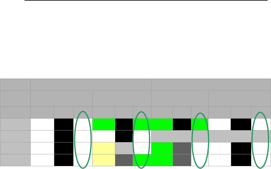
SECTION 4
A Guide for Selecting Remedies for Subsurface Releases of Chlorinated Solvents
66
reported as 0. The circled “after” results indicate that the anticipated outcome is “not
impacted” in all but the vapor phase and transmissive zone sorbed phase. By itself this
might be a sufficient remedy. Alternately, a vapor extraction system could be combined
with pump and treat to address the anticipated post-treatment vapor phase contam-
ination. Examples of combined remedies are discussed in Section 5 of this document.
Source Zone Plume
Zone/
Phases
Low Permeability Transmissive Transmissive Low Permeability
Before Tech After Before Tech After Before Tech After Before Tech After
Vapor
0 0 0 1 0 1 1 0 1 0 0 0
DNAPL
0 0 0 0 0 0
Aqueous
0 0 0 2 2 0 1 1 0 0 0 0
Sorbed
0 0 0 2 1 1 1 1 0 0 0 0
Figure 21 – Anticipated outcome from source zone pump and treat in a late-stage Type IV
setting. Boxes in the “Tech” columns show estimated performance of remedial action based
on the number of OoMs of concentration reduction. “After” values equal “before” values
minus “Tech” values.
Further insight regarding source zone pump and treat can be gained by repeating the
Figure 21 analysis for a middle stage Type III setting (e.g., heterogeneous alluvium with
less than half of the original DNAPL release remaining). This is done in Figure 22 using
the same technology ratings. The results suggest that source zone pump and treat in a
middle-stage Type III setting could leave unacceptable contaminant concentrations in all
14 compartments.

SECTION 4
A Guide for Selecting Remedies for Subsurface Releases of Chlorinated Solvents
67
Source Zone Plume
Zone/
Phases
Low Permeability Transmissive Transmissive Low Permeability
Before Tech After Before Tech After Before Tech After Before Tech After
Vapor
2 0 2 3 0 3 2 0 2 2 0 2
DNAPL
2 0 2 4 0 4
Aqueous
2 0 2 4 2 2 3 1 2 2 0 2
Sorbed
2 0 2 4 1 3 3 1 2 2 0 2
Figure 22 - Anticipated outcome from source zone pump and treat in a middle stage Type 3
setting. Boxes in the “Tech” columns show estimated performance of remedial action based
on number of OoMs of concentration reduction. “After” values equal “Before” values minus
“Tech” values.
A comparison of Figure 21 and Figure 22 illustrates:
The effectiveness of source zone pump and treat (and many other technologies)
is dependent on the setting and the stage, or age, of the release.
Care needs to be employed in discounting or strongly advocating any technology
for all situations.
Favorable Attributes – In general, pump and treat systems are relatively easy to permit,
design, and operate. Furthermore, capital costs are often low compared to other options.
They also have the potential to serve as reliable hydraulic containment systems.
Unfavorable Attributes – Use of pump and treat systems to deplete subsurface
contamination can require extended operations due to slow release of contaminant from
compartments that are not directly affected by extracting water from transmissive zones.
Long-term operations are commonly required, and cumulative operations and
maintenance costs often become burdensome.

SECTION 4
A Guide for Selecting Remedies for Subsurface Releases of Chlorinated Solvents
68
Excavation
Description - Excavation involves physical removal of
impacted sediment and water from source zones.
Options for managing excavated materials include
offsite disposal at a permitted facility, on site stabili-
zation (e.g., in a corrective action management unit),
and ex situ treatment.
Governing Processes – Excavating equipment such
as track-mounted backhoes are used to remove
impacted media. Materials are often stabilized, placed
in roll-off bins and subsequently transported to a
permitted disposal facility. Excavations below the
water table can require shoring, barriers to control
groundwater (e.g., sheet pile walls), and/or dewater systems. With highly contaminated
media, vapor emission may drive a need for respiratory protection for workers and
measures to mitigate off-site air quality impacts.
Figure 23 maps the anticipated effect of source excavation. The figure assumes that
excavation addresses the entire source zone. It is worth noting that it has been common
for excavation to miss a portion of a source. Pragmatic constraints to complete source
excavation include incomplete site characterization, surface obstructions (e.g., buildings),
and sediments that cannot be excavated. General insights from Figure 23 include:
Given ideal implementation, all contamination in the source zone will be
removed. Note that there are circumstances where this may not be possible.
Contaminants stored in the plume (e.g., in low permeability zones) can sustain
aqueous concentrations in the plume for extended periods of time. Plume
storage will be a more significant issue in aerobic plumes with little if any ongoing
degradation of contaminants in the plume.
Photo provided by Tom Sale /
Colorado State Universit
y

SECTION 4
A Guide for Selecting Remedies for Subsurface Releases of Chlorinated Solvents
69
1-2 - Depletion of the
aqueous phase in
transmissive zones will
drive release of sorbed
compounds. Note
release of sorbed
phase can be a slow
process.
Sorbed
0 - Depletion of
contamination in
the transmissive
zones results in
slow release of
aqueous and
sorbed phases
in low
permeability
zones
1-2 - Removal of the
upgradient source
should yield 1 to 2
OoM improvements in
downgradient water
quality
Aqueous
DNAPL
0 - Extraction of aqueous phase
contaminants from the transmissive
zones is likely to have little effect on
vapor phase contaminants
3-4 - Assuming that the entire source
zones is removed, and properly
backfilled, no contamination should
remain in the source zones
Vapor
Low
PermeabilityTransmissiveTransmissive
Low
Permeability
Phase /
Zone
PlumeSource Zone
Excavation 14 Compartment Performance Chart
Figure 23 – Source excavation mapped on the 14 Compartment Model for late stage Type III
setting. The plume response represents conditions several years after source removal.
Niche – Excavation is typically only applicable to source zones in unconsolidated media.
In general, the cost of excavation prohibits its use in plumes. The best-case scenario is
that excavation occurs shortly after a release occurs (early stage), meaning that little
contamination has moved into the plume (see plume Transmissive-Aqueous Figure 24).
Figure 24 maps the anticipated performance of excavation in an early-stage Type III
setting. Notes of caution in this analysis include the facts that: 1) It is rare that sources
are removed before a plume forms and 2) Complete excavation of a source is often
impractical.

SECTION 4
A Guide for Selecting Remedies for Subsurface Releases of Chlorinated Solvents
70
Source Zone Plume
Zone/
Phases
Low Permeability
Transmissive Transmissive Low Permeability
Before Tech After Before Tech After Before Tech After Before Tech After
Vapor
1 4 0 3 4 0 0 0 0 0 0 0
DNAPL
1 4 0 4 4 0
Aqueous
1 4 0 4 4 0 2 1 1 0 0 0
Sorbed
1 4 0 4 4 0 1 1 0 0 0 0
Figure 24 - Anticipated outcome from source excavation in an early stage
Type III setting.
In contrast, Figure 27 maps the anticipated performance of excavation given a late-stage
Type III setting. In this case, source excavation might do little to reduce the longevity of
aqueous and vapor concentrations in the plume. Comparison of Figure 24 and Figure 25
points to the value of rapid response to chlorinated solvent release. Specifically, rapid
response has the potential to limit the accumulation of contaminants in low permeability
zones in plumes.
Source Zone Plume
Zone/
Phases
Low Permeability
Transmissive Transmissive Low Permeability
Before Tech After Before Tech After Before Tech After Before Tech After
Vapor
2 4 0 1 4 0 1 0 1 1 0 1
DNAPL
0 4 0 0 4 0
Aqueous
3 4 0 2 4 0 2 1 1 3 0 3
Sorbed
3 4 0 2 4 0 2 1 1 3 0 3
Figure 25 - Anticipated outcome from source excavation in a late stage
Type III setting.
Favorable Attributes – Excavation involves conventional construction equipment that is
typically readily available. Given favorable conditions for excavation and practical
approaches for managing excavated materials, this is often an option that is best suited
to small releases. It is one of the most reliable methods for obtaining multiple OoM
concentration reduction in shallow source zones.

SECTION 4
A Guide for Selecting Remedies for Subsurface Releases of Chlorinated Solvents
71
Unfavorable Attributes – Highly contaminated soils may necessitate respiratory
protection for workers and measures to control offsite exposure. Excavations in unstable
soils, below the water table, and/or close to existing structures (e.g., buildings) can be
difficult and/or costly. Last, the net benefit of moving contamination from one location to
another (in the case of offsite land disposal) can be viewed as having marginal value.
Soil Vapor Extraction (SVE)
Description – SVE involves
extraction of soil gas from the
vadose zone using vacuum pumps
and conventional wells or drains.
The produced gases are often
treated prior to being discharged
into the atmosphere. Common
treatment approaches include acti-
vated carbon and thermal reactors.
Formation sweep efficiencies can be enhanced by providing vent wells or drainlines to
bring air into the targeted intervals. A comprehensive review of SVE is provided in U.S.
EPA (1997) and COE (2002).
Variations of SVE include dual phase extraction and air sparging. Dual phase extraction
involves concurrent extraction of groundwater and soil gas. Air sparging involves
concurrent injection of air into the groundwater zone and recovery of soil gas. Given the
limited use of dual phase extraction and air sparging for chlorinated solvent sites, these
technologies are not given further consideration.
Governing Processes – SVE relies on partitioning chlorinated solvent in NAPL,
aqueous, and sorbed phases (in the vadose zone) into soil gas. Slow mass transfer from
any of these phases (e.g., any of the phases in a fully saturated low permeability layer in
the vadose zone) can lead to an extended period of operations.
Courtesy of Johnson, P., R. Johnson,
and M.Marley, (2000).

SECTION 4
A Guide for Selecting Remedies for Subsurface Releases of Chlorinated Solvents
72
Anticipated Performance - Figure
26 maps the performance of SVE in the vadose zone.
Figure
26 assumes that the source zone and vapor plume occur only in the vadose zone
and, correspondingly, that there is no contamination in the groundwater zone. At many
sites, however, sources and plumes occur in both the vadose and groundwater zones. At
sites such as this, SVE would only be a partial solution as it would likely have limited
effect on the groundwater zone due to slow rates of mass transfer from groundwater
(diffusion limited) to soil vapor.
Sorbed
0-1 Low rates of
vapor flow through
low permeability
zones may yield very
slow rates of
depletion of phases
inlow permeability
zones.
2 - Partition of dissolved and sorbed
phases will sustain concentration in the
vapor phase. Extended period may be
required to achieve high levels of
depletion.
Aqueous
2 - DNAPLs can be
depleted through
direct vaporization.
Depletion of large
bodies of DNAPL
may require
extended periods.
0-1 Low rates of
vapor flow through
low permeability
zones may yield very
slow rates of
depletion of DNAPL,
aqueous, and sorbed
phase from low
permeability zones
DNAPL
0-1 High water
saturations in low
permeability may
limit extraction of
vapor from low
permeability zones
2-3 Vapor extraction will cause direct
depletion of the vapor in transmissive
zones. Effectiveness will depend on
sweep efficiencies and loading from
adjacent compartments.
0-1 High water
saturations in low
permeability may limit
extraction of vapor
from low permeability
zones
Vapor
Low
PermeabilityTransmissiveTransmissive
Low
Permeability
Phase /
Zone
PlumeSource Zone
Soil Vapor Extraction 14 Compartment Performance Chart
Figure 26 - Source excavation mapped on the 14 compartment model for late stage Type 3
vadose zone setting . Plume conditions are considered to represent conditions years
several years after source removal and near the former source.
Niche – SVE is most commonly applied in Type III settings with large depths to
groundwater. Given a large vapor phase diffusion coefficient, it is not common to find
DNAPL in the vadose zone. Consequently, most vadose zone releases are late-stage
scenarios. Figure 27 maps the anticipated performance of SVE in a late-stage Type III
setting. For the presented scenario, the primary performance limitation is addressing
contaminant in low permeability zones. Slow release of contaminant from low
permeability zones to the vadose zones is described in Barnes and McWhorter (2000).

SECTION 4
A Guide for Selecting Remedies for Subsurface Releases of Chlorinated Solvents
73
Source Zone Plume
Zone/
Phases
Low Permeability
Transmissive Transmissive Low Permeability
Before Tech After Before Tech After Before Tech After Before Tech After
Vapor
3 1 2 2 3 0 2 3 0 2 1 1
DNAPL
1 1 0 1 2 0
Aqueous
3 1 2 2 2 0 2 2 0 2 1 1
Sorbed
3 1 2 2 2 0 2 2 0 2 1 1
Figure 27 - Anticipated outcome from SVE in a vadose zone only for a late stage Type III
setting.
Favorable Attributes – In general, SVE systems are relatively easy to permit, design,
and operate. Furthermore, capital costs are generally low compared to other options.
Unfavorable Attributes – Use of SVE to deplete subsurface contamination can be a
slow process. Long-term operations are commonly required and cumulative operations
and maintenance costs often become burdensome.

SECTION 4
A Guide for Selecting Remedies for Subsurface Releases of Chlorinated Solvents
74
In Situ Degradation
Today’s primary suite of in situ degradation technologies for chlorinated solvents includes
conductive heating, chemical oxidation, biological reduction, and chemical reduction.
Thermal
Description – Heat has been delivered
to chlorinated solvent source zones using
steam, electrical resistance heating, and
conductive heating (Davis, 2008). Each
approach has advantages and limitations.
Today the most widely used approach is
conductive heating. The following section
describes conductive heating. Compre-
hensive information regarding the perfor-
mance of thermal treatment (including
conductive heating) can be found
in SERDP/ESTCP reports including
Johnson et al. (2010).
Governing Processes – Conductive heating involves placing electrical resistance
heating elements through a targeted zone. Electrical current is passed through the
resisters to generate heat that subsequently moves through the targeted media via
conduction. Contaminants are either destroyed in situ via pyrolysis or recovered via
vapor or liquid recovery systems. Recovered vapor and/or water are treated (e.g.,
thermal oxidation) prior to release. Typically, heating is continued until temperatures
throughout the target are elevated to the boiling point of water, and contaminant
concentrations in off gas fall to low levels. The target can be in the vadose zone, in the
groundwater zone, or a combination of both. In general it is more difficult to treat the
groundwater zone due to higher water content and the potential for inflow of cool
groundwater during treatment.
Anticipated Performance – Respectively, Figure 28 and Figure 29 map the anticipated
performance of conductive heating in the vadose zone and the groundwater zone. Both
figures assume that the entire source zone is addressed. Pragmatic constraints to
Image from ESTCP Report /
Johnson et al .(2010)

SECTION 4
A Guide for Selecting Remedies for Subsurface Releases of Chlorinated Solvents
75
addressing an entire source zone can include incomplete site characterization and
surface obstructions (e.g., buildings).
Vadose Zone Conductive Heating - 14 Compartment Performance Chart
0 – Reduction in
sorbed
contaminants in
the low
permeability zone
will follow
aqueous phase
concentrations in
low permeability
zones pore
1- Depletion of the
aqueous phase in
transmissive zones
will drive release of
sorbed compounds.
Note release of
sorbed phase can
be a slow process.
Sorbed
0 – Aqueous
phase diffusive
and advective
transport out of
low permeability
zones is likely to
be small
1 – Reduction in
pore water
concentration will
follow vapor phase
concentrations
Aqueous
DNAPL
0 - High water
content in low
permeability
zones may limit
release of vapor
phase
contaminant from
low permeability
zones
1 – Reductions in
diffusive flux from
the source may
reduce vapor
phase
concentrations in
the adjacent plume
3-4 - Assuming that the entire
vadose source zones is addressed
and heated for a sufficient period little
to no contamination should remain in
the source zones
Vapor
Low
PermeabilityTransmissiveTransmissive
Low
Permeability
Phase / Zone
PlumeSource Zone
Figure 28 – Vadose zone conductive heating mapped on the 14 Compartment Model. Plume
conditions are considered to represent conditions several years after source removal and
near the former source.

SECTION 4
A Guide for Selecting Remedies for Subsurface Releases of Chlorinated Solvents
76
Source Zone Plume
Phase /
Zone
Low
Permeability Transmissive Transmissive
Low
Permeability
Vapor
2-3 - Assuming that the entire source
zones is addressed and heated for a
sufficient period 1 to 2 OoM have been
observed in field projects (Kingston
2008). Treatment can be limited by in
flow of cool groundwater.
0 – Reductions in aqueous phase
contaminants from the transmissive zones
is likely to have little effect on vapor phase
contaminants
DNAPL
Aqueous 1 – A 1-2 OoM
reductions in upgradient
contaminant discharge
should yield 1 OoM
improvements in
downgradient water
quality
0 - Depletion of
contamination in
the transmissive
zones results in
slow release of
aqueous and
sorbed phases in
low permeability
zones
Sorbed 1 - Depletion of the
aqueous phase in
transmissive zones will
drive release of sorbed
compounds. Note
release of sorbed
phase can be a slow
process.
G
roundwater Zone Conductive Heating - 14 Compartment Performance Chart
Figure 29 – Groundwater zone conductive heating mapped on the 14 Compartment Model.
Plume conditions are considered to represent conditions years several years after source
removal and near the former source.
Niche – Conductive heating has been employed in both unconsolidated and consolidated
media. Given a relatively high implementation cost, it is typically only used in source
zones. Conductive heating can perform extremely well for volatile compounds in
unsaturated soils, and is also likely to be more effective with DNAPL and contaminants in
low permeability zones than injection-based degradation technologies such as
bioremediation and chemical oxidation. Figure 30 and Figure 31 map the anticipated
performance of conductive heating on middle stage Type III setting in the vadose and
groundwater zones, respectively.

SECTION 4
A Guide for Selecting Remedies for Subsurface Releases of Chlorinated Solvents
77
Source Zone Plume
Zone/
Phases
Low Permeability Transmissive Transmissive Low Permeability
Before Tech After Before Tech After Before Tech After Before Tech After
Vapor
2 3 0 3 3 0 2 1 1 2 0 2
DNAPL
2 3 0 4 4 0
Aqueous
2 3 0 4 3 0 3 1 2 2 0 2
Sorbed
2 3 0 4 3 0 3 1 2 2 0 2
Figure 30 - Anticipated outcome from vadose zone conductive heating in a middle
stage Type 3 setting.
Source Zone Plume
Zone/
Phases
Low Permeability Transmissive Transmissive Low Permeability
Before Tech After Before Tech After Before Tech After Before Tech After
Vapor
2 1 1 3 2 1 2 0 2 2 0 2
DNAPL
2 1 1 4 2 2
Aqueous
2 1 1 4 2 2 3 1 2 2 0 2
Sorbed
2 1 1 4 2 2 3 1 2 2 0 2
Figure 31 - Anticipated outcome from groundwater zone conductive heating
in a middle stage Type 3 setting.
Favorable Attributes – The potential to achieve high levels of contaminant depletion
including DNAPL and contaminants in low permeability zones has led to wide use of this
technology.
Unfavorable Attributes – Challenging attributes include:
The technical skill needed to implement this technology is high.
Cost, energy use, and carbon footprint can be high.
Incomplete heating, inflow of low-temperature groundwater, and missed portions
of the source zones can lead to significant mass remaining in source zone.
Independent of source depletion, plume concentrations can be sustained for an
extended period via release of contaminants stored in the plume.
A large number of vertical holes need to be placed through the target. Care may
be needed to limit remedy-related vertical migration of DNAPL.

SECTION 4
A Guide for Selecting Remedies for Subsurface Releases of Chlorinated Solvents
78
In Situ Chemical Reduction (ISCR)
________________________________________________________________
Description – Zero valent iron
(ZVI) can be used to drive
reductive dechlorination of most
chlorinated solvents (Gillham and
O’Hannesin, 1994). Initially, ZVI
was employed in permeable
reactors barriers (PRBs). PRBs
are covered in the following
subsection on containment. ZVI
has also been introduced to
source zones via injection and in
situ soil mixing. The following
development focuses on ZVI delivery via in situ soil mixing using a process referred to as
ZVI-Clay (Olson et al., 2011). Concurrent with mixing, a water-based grout of clay and
iron is delivered to an in situ mixing tool. Mixing can be achieved using larger-diameter
augers, backhoe-mounted hydraulic mixing tools, and/or conventional excavation
equipment. The authors are aware of nine full-scale ZVI-Clay treatments have been
completed, leading to degradation of approximately 80 tons of chlorinated solvents.
Governing Processes – Corrosion of ZVI creates thermodynamic conditions that drive
reductive dechlorination. The net effect is replacement of carbon-chlorine bonds with
carbon-hydrogen bonds. With ZVI-Clay, the clay reduces the permeability of the treated
media. One of many benefits of reduced permeability is that it extends the amount of
time over which reactions can take place. After mixing, concentrations of chlorinated
solvents in water and soil decay over time. Typical chlorinated solvent depletion
observed after one year has been in the range of 99 to 99.99%. Slower rates of treatment
may occur in areas with large amounts of DNAPL. Typical reductions in the hydraulic
conductivity of the treated body are two to four OoMs. A primary result of ZVI-Clay is a
significant reduction in contaminant discharge from the treated body through the
combined effects of reduced concentrations and groundwater flow.
Anticipated Performance – Figure 32 maps the anticipated performance of ZVI-Clay.
As with excavation and thermal treatment, the figure assumes that the entire source zone
Photo Courtesy of Chris Bozzini / CH2M HILL

SECTION 4
A Guide for Selecting Remedies for Subsurface Releases of Chlorinated Solvents
79
is addressed. Pragmatic constraints to addressing an entire source zone can include
incomplete site characterization and surface obstructions (e.g., buildings). Similar to
excavation and thermal observation from Figure 10 include:
Given ideal implementation, the vast majority of contamination in the treatment
zone will be removed.
Contaminants stored in the plume (e.g., in low permeability zones) can sustain
aqueous concentration in the plume for extended periods of time.
1-2 - Depletion of the
aqueous phase in
transmissive zones will
drive release of sorbed
compounds. Note
release of sorbed
phase can be a slow
process.
Sorbed
0 - Depletion of
contamination in
the transmissive
zones results in
slow release of
aqueous and
sorbed phases
in low
permeability
zones
1-2 - Removal of the
upgradient source
should yield 1 to 2
OoM improvements in
downgradient water
quality
Aqueous
DNAPL
0 - Extraction of aqueous phase
contaminants from the transmissive
zones is likely to have little effect on
vapor phase contaminants
2-4 - Assuming that the entire source
zones is addressed and heated for a
sufficient period no contamination
should remain in the source zones
Vapor
Low
PermeabilityTransmissiveTransmissive
Low
Permeability
Phase /
Zone
PlumeSource Zone
Figure 32 – ZVI-Clay mapped on the 14 Compartment Model. Plume conditions are
considered to represent conditions years several years after source removal and
near the former source.
Niche – Mixing with concurrent addition of treatment media is only feasible in soils that
can readily be mixed (sand, silt, and/or clay). Treatment depths of 50 feet are generally
feasible. Given a relatively high implementation cost, ZVI-Clay is typically used only in
source zones. Impressively, mixing with concurrent addition of treatment media (ZVI)
has extremely high performance even for zones containing DNAPL and contaminants in
low permeability zones. Figure 33 maps the anticipated performance of ZVI-Clay on a
middle-stage Type III setting.
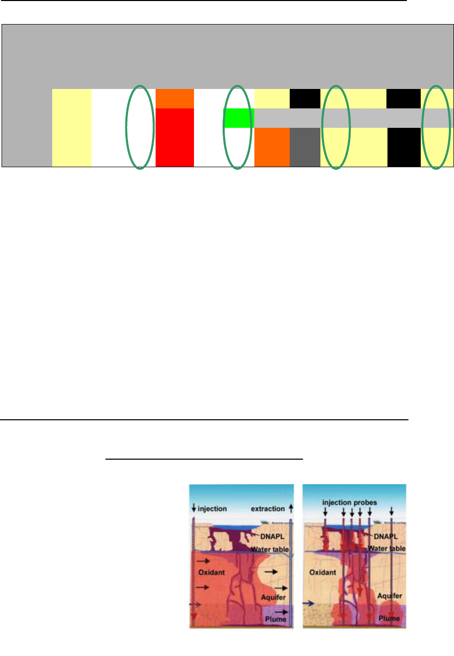
SECTION 4
A Guide for Selecting Remedies for Subsurface Releases of Chlorinated Solvents
80
Source Zone Plume
Zone/
Phases
Low Permeability Transmissive Transmissive Low Permeability
Before Tech After Before Tech After Before Tech After Before Tech After
Vapor
2 3 0 3 3 0 2 0 2 2 0 2
DNAPL
2 3 0 4 3 1
Aqueous
2 3 0 4 3 0 3 1 2 2 0 2
Sorbed
2 3 0 4 3 0 3 1 2 2 0 2
Figure 33 - Anticipated outcome from ZVI-Clay in a middle stage Type III setting.
Favorable Attributes – The technology is simple and can be implemented using readily
available equipment. It has the potential to achieve levels of treatment similar to thermal,
including DNAPL and contaminants in low permeability zones, at lower cost.
Unfavorable Attributes –
Addition of water and clay reduces the compressive strength of the treated
media. Post-treatment capping and/or soil stabilization may be required for
select land usages.
Applications are limited to sites that are largely free of surface or buried
obstructions.
In Situ Chemical Oxidation (ISCO)
Description – Chemical oxidants,
including permanganate, peroxide,
activated persulfate, and ozone, have
been used to drive in situ degradation
of chlorinated solvents. Each of these
oxidants has advantages and limita-
tions. The following discussion is
based on the use of permanganate as
the oxidant. Permanganate was the
first oxidant to be proposed (Farquhar,
1992), and typically has the advantage
Image from ESTCP Project Report / Siegrist et al.
Well-to-well flushing
Probe Injection

SECTION 4
A Guide for Selecting Remedies for Subsurface Releases of Chlorinated Solvents
81
of persisting longest in the subsurface. A limitation of permanganate is that it is typically
effective for chlorinated ethenes but not for chlorinated ethanes. Commonly, application
of ISCO involves through multiple injection events. The periods between injection events
are typically on the order of months to a year. Hundreds of ISCO remedies have been
implemented at chlorinated solvent sites. Comprehensive information regarding ISCO
can be found in SERDP/ESTCP reports including Siegrist et al. (2006) and in Brown
(2010).
Governing Processes – Strong oxidants create thermodynamic conditions that favor
replacement of carbon-chlorine bonds with carbon-oxygen bonds. As with all injection-
based remedies, achieving effective contact between reagents and contaminants can be
challenging. Constraints include:
Displacement of dissolved phase chlorinated solvents in transmissive zones by
the injected solutions
Preferential flow of reagents through intervals of high permeability
Potentially large stoichiometric oxidant demands of DNAPL
Overcoming the natural oxidant demand of sediments in the targeted treatment
zone
Density-driven flow of delivered reagents
Slow rates of reagent diffusion into low permeability zones
Post-treatment rebound of aqueous concentrations in transmissive zones, based on
water samples from wells, has commonly been observed with ISCO remedies (McGuire
et al., 2006). Possible explanations include release of contaminant from low permeability
zones, dissolution of DNAPL, and disruption in natural attenuation processes.
Anticipated Performance – Figure 34 maps the anticipated performance of
permanganate-based ISCO. The figure assumes that the entire source zone and plume
are addressed.

SECTION 4
A Guide for Selecting Remedies for Subsurface Releases of Chlorinated Solvents
82
2- Chemical oxidants can consume natural
organic carbon that sorbs chlorinated
solvents. With release from sorption sites the
contaminants can be depleted in the aqueous
phase.
Sorbed
1- Slow inward
diffusion of
permanganate into
low permeability
zones may drive
partial depletion of
contaminants in low
permeability zones.
2 – Where mixing occurs high level of
treatment can be achieved. Treatment
can be limited by non-uniform delivery
and releases from DNAPL and low
permeability zones
1- Slow inward
diffusion of
permanganate into
low permeability
zones may drive
partial depletion of
contaminants in low
permeability zones.
Aqueous
0-1 - DNAPL, if
present in large
amounts, will be
difficult to deplete
using chemical
oxidants due to
delivery and
stoichiometric
considerations
0- Slow inward
diffusion of
permanganate into
low permeability
zones and
stoichiometric
considerations will
limite effectiveness
DNAPL
0- Depletion of contaminants in the saturated zones is likely to have little effect on vapor
phase contaminants
Vapor
Low
PermeabilityTransmissiveTransmissive
Low
Permeability
Phase /
Zone
PlumeSource Zone
Figure 34 – Permanganate ISCO mapped on the 14 Compartment Model. Performance is
considered to represent conditions several years after concurrent treatment of a source
zone and plume.
Niche – Delivery of chemical oxidants via injection requires subsurface media with
moderate to high hydraulic conductivity values (> 10
-4
cm/sec). Furthermore, it may be
necessary to have injection wells on close centers (e.g., 30 feet or less). Most often
chemical injection applications have been in unconsolidated alluvium as opposed to rock.
The oxidant demand is an important component of any ISCO application: systems that
are anaerobic or anoxic with low natural organic carbon have lower natural oxidant
demands, while treatment of large DNAPL masses may be difficult due the high chemical
demand. As an example, Figure 35 maps the anticipated performance of permanganate
based ISCO on a middle-stage Type III setting.

SECTION 4
A Guide for Selecting Remedies for Subsurface Releases of Chlorinated Solvents
83
Source Zone Plume
Zone/
Phases
Low Permeability Transmissive Transmissive Low Permeability
Before Tech After Before Tech After Before Tech After Before Tech After
Vapor
2 0 2 3 0 3 2 0 2 2 0 2
DNAPL
2 0 2 4 0 4
Aqueous
2 1 1 4 1 3 3 2 1 2 1 1
Sorbed
2 1 1 4 1 3 3 2 1 2 1 1
Figure 35 - Anticipated outcome from ISCO in a middle-stage III setting.
Favorable Attributes – The technology is relatively simple and can be implemented
using common equipment.
Unfavorable Attributes – Challenging attributes include:
Post-treatment rebound and the frequent need to conduct multiple rounds of
reagent delivery
Limited contact between reactant and contaminants due to preferential flow paths
Cost associated with oxidants and delivery limit the size of treatment
Possible secondary water quality effects such as high sulfate with persulfate and
trace metal with permanganate
In Situ Biological Treatment
Description – In situ biological treatment involves addition of a soluble carbon source or
electron donor. Biologically mediated degradation of the carbon then depletes natural
electron acceptors (e.g., oxygen, nitrate, ferric iron, and sulfate) which create conditions
that favor reductive dechlorination of chlorinated ethenes. Common electron donors
include vegetable oil, molasses, lactate, and whey.

SECTION 4
A Guide for Selecting Remedies for Subsurface Releases of Chlorinated Solvents
84
In almost all instances, an
electron donor is injected into
the subsurface. Injection can
also be coupled with ground-
water extraction to draw the
electron donor through the
source zone. At most sites,
multiple cycles of injection
are employed, where typical
periods between injections
are on the order of one year.
Hundreds of in situ biological treatments have been employed at chlorinated solvent
sites. Further information regarding in situ bioremediation for source zones can be found
in SERDP/ESTCP reports, including project ER-200008 and 200438 (available at
www.serdp-estcp.org) and in ITRC (2008).
Governing Processes – Uptake of electron acceptors through biological degradation of
an electron donor creates thermodynamic conditions that favor reductive dechlorination
of chlorinated solvents (replacement of carbon-chlorine bonds with carbon-hydrogen
bonds). As with other injection-based remedies, achieving effective contact between
reagents and contaminants can be challenging. Delivery-related constraints for in situ
biological treatment include:
Displacement of dissolved phase chlorinated solvent in transmissive zones by
the injected solutions
Preferential flow of reagents through intervals of high permeability
Slow dissolution of DNAPL
The potential for limited biological activity in low permeability zones
As compared to ISCO, rebound of aqueous concentrations in transmissive zones was not
observed in the 20-site database described in McGuire et al., 2006. One possible
explanation for less rebound with biological treatment is a greater persistence of the
treatment, the buildup of endogenous biomass, and the creation of an active geochemical
zone for abiotic reactions.
Anticipated Performance – Figure 36 maps the anticipated performance of In Situ
Biological Treatment. It assumes that the source zone and plume are concurrently
addressed. A primary assumption in Figure 36 is that there will be little if any stimulation
Image from ITRC 2008

SECTION 4
A Guide for Selecting Remedies for Subsurface Releases of Chlorinated Solvents
85
of biological activity in low permeability zones. This is a hypothesis and the topic of
ongoing research. In select instances, there may be important exceptions to this
position.
1 – The stability of natural organic carbon
under reducing conditions has the
potential to sustain releases for solids.
Also, low solubility electron donor (e.g.
vegetable oil) can sorb aqueous phase
chlorinated solvents
Sorbed
0-1 - It is anticipated
that stimulation of
biological activity in
low permeability
zones will be difficult.
At best reduced
concentrations in
transmissive zone
will accelerate
release of
contaminants in low
permeability zones.
2 – Where mixing occurs high level of
treatment can be achieved. Treatment
can be limited by non-uniform delivery
and releases from DNAPL and low
permeability zones
0-1 - It is anticipated
that stimulation of
biological activity in
low permeability
zones will be difficult.
At best reduced
concentrations in
transmissive zone will
accelerate release of
contaminants in low
permeability zones.
Aqueous
Not Applicable
0-1 - DNAPL, if
present in large
amounts, will be
difficult to deplete
using biological
processes due to
delivery and
stoichiometric
considerations
0 - high
concentration in
DNAPL and the
potential for limited
biological activity in
low permeability zone
DNAPL
0- Depletion of contaminants in the saturated zones is likely to have little effect on vapor
phase contaminants
Vapor
Low
PermeabilityTransmissiveTransmissive
Low
Permeability
Phase /
Zone
PlumeSource Zone
Figure 36 – In situ bioremediation mapped on the 14 Compartment Model. Plume
conditions are considered to represent conditions years several years after
treatment of a source zone and plume.
Niche – Most applications have been in unconsolidated alluvium as opposed to rock.
Delivery via direct injection typically has injection points spaced at 30 feet or less, and
requires soils with moderate to high hydraulic conductivity values (> 10
-4
cm/sec). Plume
treatment based on electron donor addition using larger well spacing and
injection/pumping methods are also used. For example, Figure 37 maps the anticipated
performance of in situ biodegradation for source zone treatment on a middle-stage Type
III setting.

SECTION 4
A Guide for Selecting Remedies for Subsurface Releases of Chlorinated Solvents
86
Source Zone Plume
Zone/
Phases
Low Permeability Transmissive Transmissive Low Permeability
Before Tech After Before Tech After Before Tech After Before Tech After
Vapor
2 0 2 3 0 3 2 0 2 2 0 2
DNAPL
2 0 2 4 0 4
Aqueous
2 0 2 4 2 2 3 2 1 2 1 1
Sorbed
2 0 2 4 1 3 3 1 2 2 1 1
Figure 37 - Anticipated outcome from in situ biological treatment of a source zone
in a middle stage Type III setting.
Favorable Attributes – The technology is relatively simple and can be implemented
using common equipment. Also, implementation costs can be low relative to other
options.
Unfavorable Attributes – Challenging attributes include:
Implementation and monitoring may require long periods (e.g., many years)
Multiple injections of electron donor may be required
Secondary water quality issues, such as elevated levels of arsenic, heavy
metals, and methane, have been identified as a potential negative outcome of in
situ biodegradation projects.
_____________________________________________________________
Containment
At many sites consequential treatment of chlorinated solvents is impractical due to the
size of the treatment zone, ongoing land use, finite financial resources, and/or
hydrogeologic conditions. In such instances containment strategies may be the only
practicable means to attain absolute objectives. The following section reviews hydraulic
barriers, physical barriers, and permeable reactive barriers. Attributes common to all
contaminant discharge include:
Reduced contaminant discharge along a control boundary
Little if any depletion of contaminants upgradient of the control boundary

SECTION 4
A Guide for Selecting Remedies for Subsurface Releases of Chlorinated Solvents
87
_______________________________________________________________
Hydraulic Controls
Description – Extraction of groundwater
downgradient of a source can be used to
limit further contaminant discharge to a
downgradient plume. Treated water is typi-
cally treated prior to discharge to a publicly
owned water treatment plant or surface
water body. Alternatively, treated water can
be returned to the aquifer via recharge wells
or infiltration wells.
Governing Processes – Sufficient water needs to be produced from wells or drain lines
to create a hydraulic capture zone that is wide enough to capture the targeted portion of a
groundwater plume. Assuming a sloping water table, the capture zones will extend from
a finite length downgradient to a stagnation zone. Groundwater beyond the stagnation
zone will follow the regional flow pattern. Typically, the upgradient capture zone includes
the source zone.
Anticipated Performance – Figure 38 maps the anticipated performance of hydraulic
containment of a source zone. This figure represents the case where all or almost all of
the groundwater flowing through the source is captured by the pumping.
Image provided by Tom Sale
/ Colorado State University

SECTION 4
A Guide for Selecting Remedies for Subsurface Releases of Chlorinated Solvents
88
1-2 - Depletion of the
aqueous phase in
transmissive zones will
drive release of sorbed
compounds. Note
release of sorbed
phase can be a slow
process.
Sorbed
0 - Depletion of
contamination in
the transmissive
zones results in
slow release of
aqueous and
sorbed phases
in low
permeability
zones
1-2 - Removal of the
upgradient source
should yield 1 to 2
OoM improvements in
downgradient water
quality
Aqueous
DNAPL
0 - Extraction of aqueous phase
contaminants from the transmissive
zones is likely to have little effect on
vapor phase contaminants
0 - Increased groundwater flow
through the source zone associated
with downgradient pumping will do little
to reduce contaminant concentrations
in any of the source zone
compartments
Vapor
Low
PermeabilityTransmissiveTransmissive
Low
Permeability
Phase /
Zone
PlumeSource Zone
Hydraulic Containment (Source) 14 Compartment Performance Chart
Figure 38 – Hydraulic containment of a source zone mapped on the 14 Compartment
Model. Plume conditions are considered to represent conditions years several years
after implementation of hydraulic control.
Niche – Hydraulic containment can be implemented in almost any hydrogeologic setting.
It is commonly used in bedrock settings due to the limited viability of other treatment
options. Figure 39 maps the anticipated performance of hydraulic containment in a
middle-stage Type III setting. Notes of caution in this analysis include:
It is not always easy to fully capture a plume
Releases of contaminants stored in the plume, and/or slow rates of groundwater
flow in stagnant zones, may lead to persistent concentrations in the down-
gradient groundwater plume.

SECTION 4
A Guide for Selecting Remedies for Subsurface Releases of Chlorinated Solvents
89
Zone/
Source Zone Plume
Phases
Low Permeability Transmissive Transmissive Low Permeability
Before Tech After Before Tech After Before Tech After Before Tech After
Vapor
2 0 2 3 0 3 2 0 2 2 0 2
DNAPL
2 0 2 4 0 4
Aqueous
2 0 2 4 0 4 3 2 1 2 0 2
Sorbed
2 0 2 4 0 4 3 2 1 2 0 2
Figure 39 - Anticipated outcome from physical containment of a source zones of a
middle stage Type 3 setting.
Favorable Attributes – The technology is relatively simple to permit, design, implement
and operate. Initial capital costs can be low relative to other options. Often, this is the
only practical option for challenging sites such as those with contamination in deep
bedrock settings.
Unfavorable Attributes – The primary challenge is the common need for long term
operations and, correspondingly, high operations and maintenance costs.
________________________________________________________________
Physical Barriers
Description – Low permeability barriers
such as bentonite slurry walls or sheet
piling can be placed at the downgradient
edges of source zones to limit further
contaminant discharge to plumes. To
control mounding of water on the upgrad-
ient side of barriers, and/or flow around the
ends of the barriers, physical barriers often
fully surround source zones. Furthermore,
low flow pumping inside barrier walls can be employed to diminish releases via advection
and/or diffusion. This development assumes that water levels inside the physical barrier
Image provided by Chuck Newell
/ GSI Environmental Inc.

SECTION 4
A Guide for Selecting Remedies for Subsurface Releases of Chlorinated Solvents
90
are managed in such a way that adverse outward flow from the containment doesn’t
occur.
Governing Processes – Physical barriers reduce mass discharge from source zones by
diverting groundwater flow around the source. In theory, treatment of contaminants
inside physical barriers is limited, although some researchers have observed that the
elimination of fresh groundwater flow through chlorinated solvent source zones can
reduce the negative impact of competing electron acceptors such as oxygen and sulfate.
Anticipated Performance – Figure 40 maps the anticipated performance of a physical
barrier surrounding a source zone. Key assumptions include:
The physical barrier encloses the vast majority of the source zone.
Water levels inside the barrier are managed such that adverse outward flow of
groundwater doesn’t occur.
The physical barrier doesn’t have any major flaws.
Note that the 14 Compartment Model of physical containment (Figure 46) is identical to
that of hydraulic containment (Figure 38).
1-2 - Depletion of the
aqueous phase in
transmissive zones will
drive release of sorbed
compounds. Note
release of sorbed
phase can be a slow
process.
Sorbed
0 - Depletion of
contamination in
the transmissive
zones results in
slow release of
aqueous and
sorbed phases
in low
permeability
zones
1-2 - Removal of the
upgradient source
should yield 1 to 2
OoM improvements in
downgradient water
quality
Aqueous
DNAPL
0 - Extraction of aqueous phase
contaminants from the transmissive
zones is likely to have little effect on
vapor phase contaminants
0 - Increased groundwater flow
through the source zone associated
with downgradient pumping will do little
to reduce contaminant concentrations
in any of the source zone
compartments
Vapor
Low
PermeabilityTransmissiveTransmissive
Low
Permeability
Phase /
Zone
PlumeSource Zone
Physical Containment (Source) 14 Compartment Performance Chart
Figure 40 – Physical containment of a source zone mapped on the 14
Compartment model. Plume conditions are considered to represent
conditions years several years after containment.

SECTION 4
A Guide for Selecting Remedies for Subsurface Releases of Chlorinated Solvents
91
Niche – Physical barriers are comprised of vertical barriers typically installed in alluvium
or soft bedrock that can easily be excavated (slurry walls) or penetrated by direct push
systems (sheet pile walls). At many sites, a low-permeability cap is built over the
enclosed area, and a low-volume pump-and-treat system is installed to ensure an inward
hydraulic gradient. Costs for constructing vertical barriers using slurry wall technology is
very low for sites with good access, unconsolidated soils, and construction depths less
than 50 feet. Deeper construction depths are also possible, but tend to be significantly
more expensive. Figure
41 maps the anticipated performance of physical containment in
a middle-stage Type III setting. Notes of caution with this analysis include:
Past experience has shown that it is easy to miss a portion of a source zone,
resulting in source materials outside the vertical barrier.
Releases of contaminants stored in the downgradient plume and/or slow rates of
groundwater flow in stagnant zones may lead to persistent concentrations in
groundwater and vapor plume.
Source Zone Plume
Zone/
Phases
Low Permeability Transmissive Transmissive Low Permeability
Before Tech After Before Tech After Before Tech After Before Tech After
Vapor
2 0 2 3 0 3 2 0 2 2 0 2
DNAPL
2 0 2 4 0 4
Aqueous
2 0 2 4 0 4 3 2 1 2 0 2
Sorbed
2 0 2 4 0 4 3 2 1 2 0 2
Figure 41 - Anticipated outcome from physical containment of a source zones in a middle
stage Type 3 setting.
Favorable Attributes – The technology is relatively simple to permit, design, implement
and operate. For large sites physical containment often has low capital cost when
compared to in-situ source treatment options. Also groundwater treatment costs can be
minimized by including hydraulic barriers.
Unfavorable Attributes – The primary challenge is the common need for long-term
maintenance and monitoring.

SECTION 4
A Guide for Selecting Remedies for Subsurface Releases of Chlorinated Solvents
92
Permeable Reactive Barriers (PRBs)
Description – Granular zero valent
iron (ZVI) and other permeable reac-
tive media have been placed through
groundwater plumes to form reactive
barriers for chlorinated solvents.
Reactions in PRBs typically leads to
multiple order of magnitude (OoM)
reductions in concentrations immed-
iately downgradient of the barrier.
Correspondingly, multiple OoM reductions in the total mass discharge of chlorinated
solvents to downgradient plumes can be achieved. The most common reactive media
has been ZVI, and therefore the example application of the 14 Compartment Model is
based on experiences with ZVI PRBs. Emerging and experimental alternatives to ZVI
PRBs, respectively, include organic mulch (AFCEE, 2008) and electrolytic PRBs (Sale et
al., 2009). Unfortunately, as with any technology that reduces contaminant discharge
along a plane, releases of contaminants stored in downgradient portions of the plume can
sustain groundwater plume concentrations for extended periods.
General approaches for installation of ZVI PRBs include trenching and jetting. Trenching
based placement can be achieved using conventional shoring, hydraulic shoring
(polymers), and continuous trenching equipment to depth as great as 50 feet.
Emplacement of ZVI via jetting is more common for deep (>50 feet) foot installation.
Comprehensive information regarding ZVI PRBs can be found in Gavaskar (2000),
Roberts (2002), and Gavaskar (2002).
Governing Processes – Granular ZVI creates reducing conditions that drives reductive
dechlorination of chlorinated ethenes. This leads to replacement of carbon-chlorine
bonds with carbon-hydrogen bonds. Impacted groundwater is driven through PRBs via
natural hydraulic gradients. The design thickness of a ZVI PRB is dependent on
groundwater flow rates, reaction kinetics in the barrier, influent concentrations, and target
effluent concentrations. Over many years (greater than 10 years), secondary inorganic
precipitates and passivation of reaction sites on the iron can lead to reduced levels of
treatment in ZVI PRBs.
Ima
g
e Courtes
y
of EnviroMetal Technolo
g
ies Inc.

SECTION 4
A Guide for Selecting Remedies for Subsurface Releases of Chlorinated Solvents
93
Anticipated Performance – Figure 42 maps the anticipated performance of a ZVI PRB
located at the downgradient edge of a source zone. Key assumptions include:
The PRB intercepts the majority of the targeted plume emanating from
the source
The barrier doesn’t have any major flaws
Flow is largely normal to the plane of the PRB
An interesting footnote is that the 14 Compartment Model for applying an iron PRB is
identical to that of physical containment and hydraulic containment. One key difference
between PRBs and physical and hydraulic containment is that the water will flow into the
plume through the source zone, and not around the source zone. Therefore, there are
no stagnant zones immediately downgradient of the containment zone and clean water
can slowly remove contaminants from within the plume.
1-2 - Depletion of the
aqueous phase in
transmissive zones will
drive release of sorbed
compounds. Note
release of sorbed
phase can be a slow
process.
Sorbed
0 - Depletion of
contamination in
the transmissive
zones results in
slow release of
aqueous and
sorbed phases
in low
permeability
zones
1-2 - Removal of the
upgradient source
should yield 1 to 2
OoM improvements in
downgradient water
quality
Aqueous
DNAPL
0 – Depletion of aqueous phase
contaminants from the transmissive
zones is likely to have little effect on
vapor phase contaminants
0 - PRBs have no effect on upgradient
contaminant concentrations.
Vapor
Low
PermeabilityTransmissiveTransmissive
Low
Permeability
Phase /
Zone
PlumeSource Zone
ZVI PRB 14 Compartment Performance Chart
Figure 42 – ZVI PRB containment of a source zone mapped on the 14
Compartment Model. Plume conditions are considered to represent
conditions several years after emplacement of the PRB.
Niche – ZVI PRBs are typically installed in unconsolidated soils that can easily be
excavated (trench installations) or penetrated by direct push systems (jetting installations)
to depths of 50 feet or less. Deeper installation depths are possible but tend to be
significantly more expensive. Situations where large vertical gradients exist through the
interval in which PRB would be installed can create unfavorable groundwater flow

SECTION 4
A Guide for Selecting Remedies for Subsurface Releases of Chlorinated Solvents
94
patterns. Figure 43 maps the anticipated performance of a ZVI PRB immediately
downgradient of a source zone in a middle-stage Type III setting. A note of caution is
that even with relatively clean water exiting the PRB and flushing the downgradient
plume, releases of contaminants stored in the downgradient plume may lead to persistent
concentrations in groundwater.
Source Zone Plume
Zone/
Phases
Low Permeability Transmissive Transmissive Low Permeability
Before Tech After Before Tech After Before Tech After Before Tech After
Vapor
2 0 2 3 0 3 2 0 2 2 0 2
DNAPL
2 0 2 4 0 4
Aqueous
2 0 2 4 0 4 3 2 1 2 0 2
Sorbed
2 0 2 4 0 4 3 2 1 2 0 2
Figure 43 - Anticipated outcome from a PRB installed immediately downgradient of a
source zone in a middle stage Type 3 setting.
Favorable Attributes – The technology is relatively simple to permit, design, implement
and operate. In general, life cycle operations and maintenance costs are low relative to
hydraulic containment.
Unfavorable Attributes – The primary challenge is the initial capital cost associated with
installation. Based on current information, many PRBs may need replacement or
reactivation within a 10 to 30 year time period after construction.

SECTION 5
A Guide for Selecting Remedies for Subsurface Releases of Chlorinated Solvents
95
Section 5 - Developing Packages of
Remedial Measure
Last, the topic of developing comprehensive
solutions for chlorinated solvent releases is
addressed. Per NRC (2005), this last step
builds on:
A holistic understanding of the
nature of the problem (Section 2)
Objectives that are beneficial,
attainable, verifiable, and consistent
with the needs of all parties
involved (Section 3)
A site-specific understanding of
what can be achieved using proven
technologies (Section 4)
The process of developing packages of remedial measure is advanced through three
examples. The examples were inspired by three real sites where early elements of the
14 Compartment Model were used to evaluate remedial options. Attributes of each of the
sites have been intentionally modified such that none of the examples are actual sites.
Nevertheless, the authors wish to recognize the significant contributions of early adopters
of the 14 Compartment Model in developing the steps and graphical formats presented
herein. The vision of this section is that readers can follow the steps outlined or that they
may have a site that is similar to one of the examples. For each example the following
are developed:
A conceptual model that includes a 14 Compartment Model characterization
of conditions at each site.
A set of functional objectives that are used as a basis for screening remedial
actions.
An iterative development of a package of remedial measures including
anticipated outcomes in terms of contaminant distribution and attainment
of functional goals.
Are there
enough data to
determine functional
objectives?
Understanding
the Problem
Is there a source?
1b. Collect Data and
Refine SCM
2. Identify Absolute Objectives
3. Identify Functional Objectives
and Metrics
4. Identify Potential Technologies
5. Select among Technologies
and Refine Metrics
6. Design and Implement
Chosen Technology
Are there
enough data to
determine if a source
exists?
Developing
Objectives
Are there
enough data to select
potential tech-
nologies?
Is there
sufficient information
to resolve if the objectives
have been
achieved?
Resolving What
is Attainable
Have
objectives been
met?
Selecting
Remedies and
Performance
Metrics
DONE
Verifying
Desired
Performance
NO
NO
NO
NO
NO
YES
YES
YES
NO
YES
1a. Review Existing Site Data
and Preliminary SCM
YES
YES
YES
Are there
enough site-specific
data to choose among
technologies?
NO
YES
NO
Are
there enough
data to design and
implement the
remedy?
If there are
no viable
choices
If there are
no viable
choices

SECTION 5
A Guide for Selecting Remedies for Subsurface Releases of Chlorinated Solvents
96
It is worth noting that development of each of the examples leads to novel ways of
applying the 14 Compartment Model. We encourage readers to consider what we have
done and recognize the opportunity to adapt our methods to their own needs.
Example 1 – A Large Instantaneous Release of PCE DNAPL
Site Conceptual Model
Background - Example 1 involves a large industrial facility where piping on a
storage tank failed. This caused a rapid release of approximately 10,000 gallons of
perchloroethene (PCE). The PCE release occurred into a thick, highly heterogeneous
alluvial fan deposit containing interbeds of moderately to poorly sorted silt, fine sand, and
coarse sand. Over a period of twenty years, a plume extended from the release area, or
source zone, downgradient across the industrial property and ultimately into an adjacent
residential neighborhood.
Figure 44 provides plan-view and cross-sectional representations of the site. For real
sites, data can be overlain on plan-view maps and cross-sections to develop similar
representation. The plume length is approximately 1 mile. The depth to top of the water
table is a few tens of feet below ground surface (bgs). The depth to the base of PCE
contamination is on the order of 40-60 feet bgs. The plume is aerobic and the absence of
PCE degradation products suggests that there is little if any natural biological degradation
of PCE occurring. The apparent transport velocity in the plume is 1 mile in twenty years
or 260 feet/year. The apparent attenuation of aqueous phase concentrations with
distance is attributed to the combined effects of sorption in transmissive zones and
storage of contaminant in low permeability zones. The idea of ongoing contaminant
storage in low permeability zones is stylistically shown by low permeability interbeds
(lenses with dashes) that have higher concentrations at their margins than in their
interiors.

SECTION 5
A Guide for Selecting Remedies for Subsurface Releases of Chlorinated Solvents
97
.
.
.
.
30
.
.
.
..
.
.
.
.
.
.
.
.
.
.
.
..
.
.
.
.
.
.
.
.
.
.
.
.
.
.
.
.
.
.
.
.
.
.
..
.
.
.
.
.
.
.
.
.
.
.
..
.
.
.
.
.
.
.
.
.
.
..
.
.
.
.
.
.
.
.
..
.
..
.
.
.
.
.
.
.
.
.
.
.
..
.
.
.
.
.
.
.
.
.
.
..
.
.
.
.
.
.
.
.
..
.
.
.
.
.
.
.
.
.
.
.
.
.
.
.
.
.
.
.
.
.
.
.
.
.
.
.
.
.
.
.
..
.
.
.
..
.
.
.
.
..
.
.
.
.
.
.
.
.
.
.
..
.
.
.
.
.
.
.
.
.
..
.
.
.
.
.
.
.
.
.
.
..
.
.
.
.
.
.
.
.
.
.
.
.
.
.
.
.
.
.
.
ND
ND ND
ND
ND
ND
ND
ND
ND
100
80
60
40
20
24000
4000
21000
900
200
400
35
80
15
3800
10
2
7
ND
.
Source
zone
Source
zone
Industrial
Industrial
Residential
Residential
Onsite plume
Onsite plume
Onsite plume
Onsite plume
Onsite plume
Onsite plume
Figure 44 – Plan-view and cross-sectional representation of Example Site 1.
Note that Figure 44 splits the release into a source zone, an onsite plume, and an offsite
plume. The subdivision of the plume into onsite and offsite elements is necessitated by a
number of factors including different onsite and offsite:
Exposure scenarios
Access constraints
Plume concentrations
Objectives
Mapping Contaminant Distribution and Fluxes - Figure 45 employs a 14 Compartment
Model OoM depiction of the contaminant distribution and contaminant fluxes. Per the
terminology introduced in Section 2, the site is a middle-stage Type III site. Note that
following the development in Figure 44, the 14 compartment representation in Figure 45
has been modified (relative to presentations in Sections 1 and 3) to include separate sets
of compartments for the onsite and offsite plumes. The concentration estimates in Figure
45 were developed by first looking at available water quality and soil gas data. This
information was used to inform the aqueous and vapor phase concentrations in
transmissive zones. The remaining compartments were filled in based on anticipated
partitioning between phases and transmissive and low permeability zones per the
processes described in Section 2. Unfortunately, as has been typical for many sites
historically, no data were available from low permeability zones. For sites where critical
information is missing, efforts should be made to collect the information needed to make
fully informed decisions. As a footnote, development of 14 Compartment Models can
help inform decisions regarding collection of additional data. Last, Figure 45 also shows

SECTION 5
A Guide for Selecting Remedies for Subsurface Releases of Chlorinated Solvents
98
the critical points where human exposures seem most likely to occur (offsite indoor air -
house icon and groundwater - well icon). As such, the 14 Compartment Model is also
used to develop a conceptual model for exposure pathways.
Offsite GW
Offsite indoor air
.
.
.
.
30
.
.
.
..
.
.
.
.
.
.
.
.
.
.
.
..
.
.
.
.
.
.
.
.
.
.
.
.
.
.
.
.
.
.
.
.
.
.
..
.
.
.
.
.
.
.
.
.
.
.
..
.
.
.
.
.
.
.
.
.
.
..
.
.
.
.
.
.
.
.
..
.
..
.
.
.
.
.
.
.
.
.
.
.
..
.
.
.
.
.
.
.
.
.
.
.
..
.
.
.
.
.
.
.
.
.
.
.
..
.
.
.
.
.
.
.
.
.
.
.
.
.
.
.
.
.
.
.
.
.
.
.
.
.
.
.
.
.
.
.
.
.
.
.
..
.
.
.
.
..
.
.
.
.
.
..
.
.
.
.
.
.
.
.
.
.
.
..
.
.
.
.
.
.
.
.
.
.
.
..
.
.
.
.
.
.
.
.
.
.
.
..
.
.
.
.
.
.
.
.
.
.
.
.
.
.
.
.
.
.
.
.
.
ND
ND ND
ND
ND
ND
ND
ND
ND
100
80
60
40
20
24000
4000
21000
900
200
400
35
80
15
3800
10
2
7
1200 1400 1800 2000 2200 2400 2600 2800 3000 3200 3400 3600 3800 4000 4200 4600 4800 5000 5200
ND
Source zone
On site plume
Offsite plume
Industrial
Industrial
Residential
Residential
Source Zone Onsite Plume Offsite Plume
Zone/
Phases
Low
Permeability
Transmissive Transmissive Low
Permeability
Transmissive Low
Permeability
Vapor
3 3 2 2 2 2
DNAPL
3 4
Aqueous
3 4 3 2 2 2
Sorbed
3 3 3 2 2 2
Figure 45 – Plan-view and cross-sectional representation with 14-compartment
mapping of Example Site 1.
Objectives
The next step in advancing Example 1 is to develop a set of absolute and functional
objectives for the site. Key drivers for stakeholders are:
Locally, home owners in the residential area are concerned about potential
health effects, potential impacts to property values, and undue disruptions in the
neighborhood.
Regionally, the community is committed to a clean environment while wanting to
preserve jobs.
The facility owners are committed to immediately addressing any complete
exposure pathways and meeting all other obligations within the constraints of:
o A preference for actions that have consequential benefits
o Working within the bounds of what is economically feasible
o A preference for solutions with low operations and maintenance
requirements.

SECTION 5
A Guide for Selecting Remedies for Subsurface Releases of Chlorinated Solvents
99
Regulators wish to support the interests of the community, provide technical
support to all parties, and pursue compliance with applicable rules and
regulations.
Building on the discussion of absolute objectives presented in Section 3, our hypothetical
(envisioned mutual consent) absolute objectives are:
Protection of human health and the environment
Addressing adverse community impacts
Minimization of the burden of past practices on future generations
Conservation of natural resources
Our hypothetical functional objectives are presented in the first column of Table
4.
Additional columns to the right of the functional objectives provide a basis for qualitative
ranking of how well a select action or set of actions meets the desired result in the near
term (a few years) or long term (a decade or more). Inclusive to the option is the “status
quo.” For this example, the status quo includes no active uses of groundwater, and
vapor mitigation system on homes with potentially unacceptable indoor air contamination.
The adjacent image provides an OoM rating system for attainment of functional
objectives. The OoM attainment rating system is applied for the status quo in Table 4.
Pragmatically, any new set of actions should result in a consequential improvement over
the status quo.
Advancement of a Package of Remedial Measures
Advancement of a package of remedial measures is envisioned as an iterative process in
which options are proposed, performance is anticipated, and complementary measures
are added to address limitations. Our vision is that all parties with relevant interests
should participate in roles that are appropriate for their interests and abilities. Our first
step in this process is resolving a “first cut” set of actions that are given and, conversely,
actions that are unlikely. For this example elements that are given and unlikely elements
include:
Given
o Land use restrictions that preclude future use of groundwater in the
impacted area for the foreseeable future.
o Maintenance of vapor mitigation on all homes where a potential for
adverse site related impacts exists.
o Long-term monitoring to verify the protectiveness of the site remedy.

SECTION 5
A Guide for Selecting Remedies for Subsurface Releases of Chlorinated Solvents
100
Unlikely
o Measures that would preclude reasonable continuous habitation of the
homes in impacted areas.
o Measures that would cause the industrial facility to close.
Table 4 – Functional objectives and status quo rating for Example Site 1
Status
Quo
Term in which the result is anticipated S
h
o
r
t
L
o
n
g
Risk
Mitigate adverse human exposure via soil gas given current and
reasonable future use
Mitigate adverse human exposure via groundwater given current
and reasonable future use
Mitigate adverse worker-related exposures via soil, groundwater,
and/or soil vapor
Avoid actions that have the potential to increase risk
Extent
Prevent expansion of plumes
Reduce the extent of plumes
Longevity
Reduce the period in which persistent releases to groundwater
occur.
Reduce the period in which releases to soil gas occur.
Regulatory
Comply with local, state, and federal regulations
Community
Avoid undue interruptions to community
Land use
Restore beneficial use of impacted lands
Economic
Select actions that have a practical near-term capital cost and
minimal life cycle cost
Sustainability
Select measures that have a net positive environmental benefit
Avoid undue remedy-related interruptions to communities,
government, and industry activities
Resource Conservation
Limit future degradation of natural resources
Restore impacted groundwater to standards needed for
beneficial use
Implementations
Select remedies that are practical to install

SECTION 5
A Guide for Selecting Remedies for Subsurface Releases of Chlorinated Solvents
101
For our hypothetical example we assume that the interested parties propose two
divergent options of:
Source depletion via in situ conductive heating
Source containment via a bentonite slurry wall and low flow hydraulic
containment
Figure
46 and Figure 47 anticipate the outcome of the above actions. The performance
is based on the conditions identified in Figure 45 and the maps of technology
performance presented in Section 4. One variation from the Section 4 input is the
anticipated result that an OoM improvement in aqueous concentrations in transmissive
zones in the plume will yield an OoM improvement in vapor concentrations in
transmissive zones in the plume. This points out the fact that the anticipated
performances for technologies described in Section 4 are guides, not fixed results.
.
.
.
.
30
.
.
.
..
.
.
.
.
.
.
.
.
.
.
.
..
.
.
.
.
.
.
.
.
.
.
.
.
.
.
.
.
.
.
.
.
..
.
.
.
.
.
.
.
.
.
.
..
.
.
.
.
.
.
.
.
.
.
..
.
.
.
.
.
.
.
.
..
.
..
.
.
.
.
.
.
.
.
.
.
.
..
.
.
.
.
.
.
.
.
.
.
.
..
.
.
.
.
.
.
.
.
.
.
.
..
.
.
.
.
.
.
.
.
.
.
.
.
.
.
.
.
.
.
.
.
.
.
.
.
.
.
.
.
.
.
.
.
.
.
.
..
.
.
.
.
..
.
.
.
.
.
..
.
.
.
.
.
.
.
.
.
.
.
..
.
.
.
.
.
.
.
.
.
.
.
..
.
.
.
.
.
.
.
.
.
.
.
..
.
.
.
.
.
.
.
.
.
.
.
.
.
.
.
.
.
.
.
.
.
ND
ND ND
ND
ND
ND
ND
ND
ND
100
80
60
40
20
24000
4000
21000
900
200
400
35
80
15
3800
10
2
7
1200 1400 1800 2000 2200 2400 2600 2800 3000 3200 3400 3600 3800 4000 4200 4600 4800 5000 5200
ND
.
Treated
zone
Treated
zone
Onsite plume
Onsite plume
Onsite plume
Onsite plume
202112202213123123
Sorbed
202112202213224123
Aqueous
224123
DNAPL
202112202112123123
Vapor
After
Tech
Before
After
Tech
Before
After
Tech
Before
After
Tech
Before
After
Tech
Before
After
Tech
Before
Low
Permeability
TransmissiveLow
Permeability
TransmissiveTransmissiveLow
Permeability
Zone/
Phases
Offsite PlumeOnsite PlumeSource Zone
Figure 46 – Near-term (~5 years) effect of source depletion via in situ conductive heating

SECTION 5
A Guide for Selecting Remedies for Subsurface Releases of Chlorinated Solvents
102
.
.
.
.
30
.
.
.
..
.
.
.
.
.
.
.
.
.
.
.
..
.
.
.
.
.
.
.
.
.
.
.
.
.
.
.
.
.
.
.
..
.
.
.
.
.
.
.
.
.
.
..
.
.
.
.
.
.
.
.
.
.
..
.
.
.
.
.
.
.
.
..
.
..
.
.
.
.
.
.
.
.
.
.
.
..
.
.
.
.
.
.
.
.
.
.
.
..
.
.
.
.
.
.
.
.
.
.
.
..
.
.
.
.
.
.
.
.
.
.
.
.
.
.
.
.
.
.
.
.
.
.
.
.
.
.
.
.
.
.
.
.
.
.
.
..
.
.
.
.
..
.
.
.
.
.
..
.
.
.
.
.
.
.
.
.
.
.
..
.
.
.
.
.
.
.
.
.
.
.
..
.
.
.
.
.
.
.
.
.
.
.
..
.
.
.
.
.
.
.
.
.
.
.
.
.
.
.
.
.
.
.
.
.
ND ND
ND
ND
ND
ND
ND
ND
100
80
60
40
20
900
200
400
35
80
15
10
2
7
1200 1400 1800 2000 2200 2400 2600 2800 3000 3200 3400 3600 3800 4000 4200 4600 4800 5000 5200
ND
.
Contained
zone
Contained
zone
Onsite plume
Onsite plume
Onsite plume
Onsite plume
202112202213303303
Sorbed
202112202213404303
Aqueous
404303
DNAPL
202112202112303303
Vapor
After
Tech
Before
After
Tech
Before
After
Tech
Before
After
Tech
Before
After
Tech
Before
After
Tech
Before
Low
Permeability
TransmissiveLow
Permeability
TransmissiveTransmissiveLow
Permeability
Zone/
Phases
Offsite PlumeOnsite PlumeSource Zone
.
.
ND
24000
4000
21000
3800
Figure 47 – Near-term (~5 years) effect of source containment via a bentonite slurry wall
and low flow hydraulic containment
From a performance perspective, the primary difference between the two options is that
thermal treatment depletes the source and while containment has little effect on
contaminants in the source zone. From an OoM perspective, both options have similar
results in the onsite and offsite plumes. Further insights regarding the merits of the
options are provided in Table 5.
Per Table 5, other differences between the options are a higher capital cost and a greater
disruption of site activities with the thermal options. Conversely, containment has a
higher life cycle cost due to a need for long-term operation and maintenance primarily
associated with hydraulic control. A limitation common to both actions is slow and only
partial improvement in aqueous and vapor concentrations in the offsite plume.

SECTION 5
A Guide for Selecting Remedies for Subsurface Releases of Chlorinated Solvents
103
Table 5 – Example 1 - Analysis of the status quo, thermal treatment of the source and
containment of the source
Status
Quo
Therma
l
Contain
-ment
Term in which the result is anticipated S
h
o
r
t
L
o
n
g
S
h
o
r
t
L
o
n
g
S
h
o
r
t
L
o
n
g
Risk
Mitigate adverse human exposure via soil gas given current and
reasonable future use
Mitigate adverse human exposure via groundwater given current
and reasonable future use
Mitigate adverse worker-related exposures via soil, groundwater,
and/or soil vapor
Avoid actions that have the potential to increase risk
Extent
Prevent expansion of plumes
Reduce the extent of plumes
Longevity
Reduce the period in which persistent releases to groundwater
occur
Reduce the period in which releases to soils gas occur
Regulatory
Comply with local, state, and federal regulations
Community
Avoid undue interruptions to community
Land use
Restore beneficial use of impacted lands
Economic
Select actions that have a practical near-term capital cost and
minimal life cycle cost
Sustainability
Select measures that have a net positive environmental benefit
Avoid undue remedy-related interruptions to communities,
government, and industry activities
Resource Conservation
Limit future degradation of natural resources
Restore impacted groundwater to standards needed for
beneficial use
Implementations
Select remedies that are practical to install
Building on the Table 5 analysis, the following modifications to the thermal and
containment options are proposed:
For both options, an iron permeable reactive barrier (PRB) will be added at the
downgradient edge of the onsite plume. This will reduce the time needed to see
improvements in aqueous and vapor phase concentrations in the offsite
(residential) plume.

SECTION 5
A Guide for Selecting Remedies for Subsurface Releases of Chlorinated Solvents
104
For containment, an electron donor (e.g., emulsified vegetable oil) will be injected
inside the bentonite slurry wall. Biological treatment is anticipated to eliminate
the need for hydraulic controls inside the containment zone and, over the long
term, will achieve depletion of contaminants in the source zone similar to that of
the thermal treatment.
Given these additions, the performance of both options from an OoM perspective is
similar.
Figure 48 anticipates the outcome of enhanced options, referred to as containment plus
and thermal plus. Last, Table 6 compares the status quo, thermal plus, and containment
plus. We will assume (given the two options’ similar treatment outcomes) that
containment plus was selected based on its lower cost and greater compatibility with
ongoing industrial land use. This is where we end this example. Nevertheless, it could
be carried further. For instance, active treatment could be added for the offsite plume.
While active treatment in the offsite plume could yield further improvements in offsite
water and soil gas quality, it might come with unacceptable disruptions to residences.
Another path for the analysis would be to revisit the functional objectives. As an
example, allowance for attainment of the objective over a longer period of time might be
the best way to achieve more complete attainment of the function objectives. As can be
seen by comparing short- and long-term results, the outcome from actions can improve
with time.

SECTION 5
A Guide for Selecting Remedies for Subsurface Releases of Chlorinated Solvents
105
.
.
.
.
30
.
.
.
..
.
.
.
.
.
.
.
.
.
.
.
..
.
.
.
.
.
.
.
.
.
.
.
.
.
.
.
.
.
.
.
.
..
.
.
.
.
.
.
.
.
.
.
..
.
.
.
.
.
.
.
.
.
.
..
.
.
.
.
.
.
.
.
..
.
..
.
.
.
.
.
.
.
.
.
.
.
..
.
.
.
.
.
.
.
.
.
.
.
..
.
.
.
.
.
.
.
.
.
.
.
..
.
.
.
.
.
.
.
.
.
.
.
.
.
.
.
.
.
.
.
.
.
.
.
.
.
.
.
.
.
.
.
.
.
.
.
..
.
.
.
.
..
.
.
.
.
.
..
.
.
.
.
.
.
.
.
.
.
.
..
.
.
.
.
.
.
.
.
.
.
.
..
.
.
.
.
.
.
.
.
.
.
.
..
.
.
.
.
.
.
.
.
.
.
.
.
.
.
.
.
.
.
.
.
.
ND
ND ND
ND
ND
ND
ND
ND
ND
100
80
60
40
20
24000
4000
21000
900
200
400
35
80
15
3800
10
2
7
1200 1400 1800 2000 2200 2400 2600 2800 3000 3200 3400 3600 3800 4000 4200 4600 4800 5000 5200
ND
.
Source
zone
Source
zone
Onsite plume
Onsite plume
Onsite plume
Onsite plume
202112202213123123
Sorbed
202112202213224123
Aqueous
224123
DNAPL
202202202202123123
Vapor
After
Tech
Before
After
Tech
Before
After
Tech
Before
After
Tech
Before
After
Tech
Before
After
Tech
Before
Low
Permeability
TransmissiveLow
Permeability
TransmissiveTransmissiveLow
Permeability
Zone/
Phases
Offsite PlumeOnsite PlumeSource Zone
Figure 48 – Near-term (~5 years) effect of source containment via a bentonite slurry
wall, PRB, and addition of an electron acceptor inside the slurry wall.

SECTION 5
A Guide for Selecting Remedies for Subsurface Releases of Chlorinated Solvents
106
Table 6 – Example 1 - Analysis of the status quo, thermal plus, and
containment plus.
Status
Quo
Therma
l
Plus
Contain
-ment
Plus
Term in which the result is anticipated S
h
o
r
t
L
o
n
g
S
h
o
r
t
L
o
n
g
S
h
o
r
t
L
o
n
g
Risk
Mitigate adverse human exposure via soil gas given current and
reasonable future use
Mitigate adverse human exposure via groundwater given current
and reasonable future use
Mitigate adverse worker-related exposures via soil, groundwater,
and/or soil vapor
Avoid actions that have the potential to increase risk
Extent
Prevent expansion of plumes
Reduce the extent of plumes
Longevity
Reduce the period in which persistent releases to groundwater
occur
Reduce the period in which releases to soil gas occur
Regulatory
Comply with local, state, and federal regulations
Community
Avoid undue interruptions to community
Land use
Restore beneficial use of impacted lands
Economic
Select actions that have a practical near-term capital cost and
minimal life cycle cost
Sustainability
Select measures that have a net positive environmental benefit
Avoid undue remedy-related interruptions to communities,
government, and industry activities
Resource Conservation
Limit future degradation of natural resources
Restore impacted groundwater to standards needed for
beneficial use
Implementations
Select remedies that are practical to install

SECTION 5
A Guide for Selecting Remedies for Subsurface Releases of Chlorinated Solvents
107
Summary –
In this example a package of remedial measures was developed through a collaborative-
iterative process. Outcomes of the proposed actions were anticipated using the 14
Compartment Model and the maps of technology performance introduced in Section 4. A
set of actions is advanced that provides consequential improvements over the status quo.
At the same time, the solution leaves contaminants in places that will only be addressed
by presumably slow natural attenuation processes. In the end, accepting a solution of
this nature would be a matter of valuing what can pragmatically be achieved while
planning to manage what remains.
Example 2 – A Small Release of TCE after 10 years of
Hydraulic Containment
Site Conceptual Model
Background
- Example 2 involves a 1950s-60s era munitions manufacturing facility
where TCE was used for maintenance of munitions assembly systems and final cleaning
of munitions. Process wash waters were conveyed via sewers to a pond with no
discharge points. Influent flows to the pond were accommodated by evaporation and
seepage losses. Seepage losses were on the order of 100s of thousand of gallon per
day. Given the large volume of water and limited usages of TCE at the site, TCE
released from the ponds occurred primarily in an aqueous phase. As such, there were
no consequential DNAPL releases at the site, and the site does not have a source zone.
A source zone is defined (per NRC, 2005) as a subsurface body in which DNAPL was
released. The absence of TCE DNAPL is also consistent with the relatively high aqueous
solubility of TCE (0.1%).
However, water released from the pond did contain tens of mg/L of TCE in the dissolved
phase. As shown in Figure 49, the resultant plume extends for approximately one mile
downgradient to a surface water body. The surface water body is the local discharge
point for groundwater. A large part of the depth and width of the downgradient plume is
attributed to the hydraulic drive created by recharge coming from the pond. Furthermore,
rapid movement of the plume from the pond to the surface water body is attributed to the
hydraulic gradients created by the mounding of groundwater beneath the pond. Current

SECTION 5
A Guide for Selecting Remedies for Subsurface Releases of Chlorinated Solvents
108
rates of groundwater flow, under the natural gradient, are on the order of 100 feet
per year.
Geologically, the subsurface includes heterogeneous glacial outwash containing
transmissive sands with interbeds of low permeability silt (0 to 40 ft bgs). Low
permeability lenses in the transmissive sands are depicted stylistically as elliptical lenses
with either inward or outward concentration gradients. Observed low oxidation-reduction
potential (ORP) and the presence of TCE degradation products suggests that TCE is
being reductively degraded, albeit slowly, via natural biological processes.
In 1970, the site operations that created the TCE plume ended. In 2000, a groundwater
hydraulic control barrier was installed. Since 2000 groundwater has been produced
using a line of recovery wells located downgradient of the pond. Produced water is
treated via air stripping with no off gas treatment. Treated water is returned to the aquifer
via a shallow onsite recharge ponds. Current conditions, including the distribution of
contamination after ten years of hydraulic control, are depicted in Figure 50.
Figure 49 - Site setting and mature plumes prior to implementation
of site remedies.

SECTION 5
A Guide for Selecting Remedies for Subsurface Releases of Chlorinated Solvents
109
Figure 50 - Site setting and contaminant distribution 10 years after
implementation of hydraulic control at the property boundary.
Figure 49 and Figure 50 divide the release into shallow and deep - onsite, near offsite,
and distal offsite plumes. The subdivisions are necessitated by a number of factors
including different:
Exposure scenarios,
Access constraints,
Plume concentrations,
Applicable technologies, and
Objectives.
Offsite concerns exist with indoor air and groundwater. All homeowners have been
offered no-cost vapor mitigation systems. Many, but not all, of the homeowners in
affected areas have accepted the offer. All homes are provided water via a fully
compliant municipal water supply district. Despite notification to the community, it is
possible that a few shallow unpermitted (and infrequently used) irrigation wells may be
present in the neighborhood. An additional concern is the impact of offsite contamination
to residential property values. Given a depressed local housing market, separating real
and perceived property value impacts is difficult. Currently there is no active use of the
industrial property. Another community concern is the inactive nature of the former
industrial property.
Mapping Contaminant Distribution and Fluxes -
Figure 51
presents a 14 Compartment Model OoM depiction of the contaminant
distribution before and after 10 years of hydraulic control. Before and after conditions

SECTION 5
A Guide for Selecting Remedies for Subsurface Releases of Chlorinated Solvents
110
are depicted in the columns labeled “before” and “after.” The following variations from
the standard 14 Compartment Model have been employed:
Six separate compartment models have been employed for different parts of
the plume.
Since DNAPL is not present, rows with the DNAPL have been eliminated.
There are no consequential transmissive zones in the deep lacustrine clay;
hence, columns for transmissive zones have been eliminated in the deep
plume compartment models.
Both “before” and “after” conditions are based on field data. The technology rating “Tech”
is based on the observed difference between “before” and “after” conditions. This
presents another novel application of the 14 Compartment Model. It can be used to
develop site-specific maps of technology performance based on observed “before” and
“after” conditions. As a check, the observed performance “Tech” of hydraulic control is
similar to the general analysis of the performance of hydraulic control presented in
Section 4.
2
02112303213224404
Sorbed
2
02112303213224404
Aqueous
2
02101202112213303
Vapor
After
Tech
Before
After
Tech
Before
After
Tech
Before
After
Tech
Before
After
Tech
Before
After
Tech
Before
Low PermeabilityTransmissiveLow PermeabilityTransmissiveTransmissiveLow Permeability
Zone/
Phases
Shallow Distal Offsite PlumeShallow Near Offsite PlumeShallow Onsite Plume
Deep Onsite
Plume
Deep Near
Offsite Plume
Deep Distal
Offsite Plume
Zone/
Phases
Low
Permeability
Low
Permeability
Low
Permeability
Before
Tech
After
Before
Tech
After
Before
Tech
After
Aqueous
3 0 3 2 0 2 1 0 1
Sorbed
3 0 3 2 0 2 1 0 1
Shallow
Onsite
Plume
Shallow
Near
Offsite
Plume
Shallow
Distal
Offsite
Plume
Deep Onsite
Plume
Deep Near
Offsite
Plume
Shallow Distal
Offsite Plume
Figure 51 - Cross-sectional representation with 14-compartment mapping of Example Site 2.
“Before” and “After” depicts observed conditions before and 10 years after hydraulic
control. In this example the Technology Performance “Tech” was not estimated, but

SECTION 5
A Guide for Selecting Remedies for Subsurface Releases of Chlorinated Solvents
111
calculated based on actual knowledge of “Before” and “After” concentrations in the
transmissive compartments.
Per the terminology introduced in Section 2:
Both the shallow and deep plumes are late-stage scenarios
The shallow plume is in a Type III geologic setting
The deep plume is in a Type II geologic setting
In more detail, the “before” and “after” mappings of contaminant distribution in
Figure 51
were developed by first looking at available water quality and soil gas data.
This information was used to inform the aqueous and vapor phase concentrations in
transmissive zones. The remaining compartments were filled in based on anticipated
partitioning between phases and transmissive and low permeability zones per the
processes described in Section 2. Unfortunately, as was the case in the first example, no
data was available from low permeability zones. For sites where critical information is
missing efforts should be made to collect the information needed to make fully informed
decisions. Again, attempts to fill in the 14 Compartment model can help inform site
managers where they are lacking key data, such as concentrations of contaminants in
low-permeability zones.
Last, Figure 45 also shows compartments where human exposure seems most likely to
occur (offsite indoor air - house icon and groundwater well - icon). As with the first
example, the 14 Compartment Model is used to resolve exposure pathways. Critically, in
this example, discharge of chlorinated solvents to surface water is not a primary concern.
For this example, limited concerns with site related impact to surface water reflects other,
more significant, water quality issues in the surface water body.
Objectives
Next, a “first cut” set of absolute and functional objectives are advanced for the site. As
described in Section 3, should any of the functional objectives prove to be unattainable,
an option for subsequent iterations is to replace the functional objective with a refined
objective of equal value that is attainable. Key drivers for stakeholders at Example Site 2
are:

SECTION 5
A Guide for Selecting Remedies for Subsurface Releases of Chlorinated Solvents
112
Locally, homeowners in the residential area are concerned about potential health
effects, potential impacts to property values, and undue disruptions in the
neighborhood.
Regionally, the community is committed to a clean environment while wanting to
find new uses for closed industrial properties in the area.
The facility owners are committed to immediately addressing any complete
exposure pathways and meeting all other obligations within the constraints of:
o A preference for actions that have consequential benefits
o Working within the bounds of what is economically feasible
o A preference for solutions with low operations and maintenance
requirements.
Regulators wish to support the interests of the community, provide technical
support to all parties, and pursue compliance with applicable rules and
regulations.
Building on the discussion of absolute objectives presented in Section 3, our hypothetical
(envisioned mutual consent) absolute objectives are:
Protection of human health and the environment
Address adverse community impacts
Conservation of natural resources
Hypothetical functional objectives are presented in the first column of Table 7. Additional
columns in Table 7 to the right of the functional objectives, provide a basis for qualitative
ranking of how well a select action or set of actions meets the desired result in the near
term (a few years) or long term (a decade or more). Inclusive to the option is the status
quo. For this example the status quo includes:
Continuation of the hydraulic containment
Maintaining vapor mitigation systems
Monitoring
The adjacent image provides an OoM rating
system for attainment of functional objectives.
The OoM attainment rating system is applied
for the status quo in Table 7. Pragmatically,
any new set of actions should result in
a consequential improvement over the
status quo.
OoM Ratings for Attainment of Functional Objectives
Favorable attainment
Cautionary partial attainment
No clear benefit
Concerns regarding adverse
outcome

SECTION 5
A Guide for Selecting Remedies for Subsurface Releases of Chlorinated Solvents
113
Table 7 – Functional objectives and status quo rating for Example Site 2
Status
Quo
Term in which the result is anticipated S
h
o
r
t
L
o
n
g
Risk
Mitigate adverse human exposure via soil gas
Mitigate adverse human exposure via groundwater
Avoid actions that have the potential to increase risk
Extent
Reduce the extent of plumes
Longevity
Reduce the period in which persistent releases to groundwater
occur
Reduce the period in which persistent releases to soil gas occur
Regulatory
Comply with local, state, and federal regulations
Community
Avoid undue interruptions to community
Address concerns regarding impacts to offsite property values
Land use
Restore beneficial use of the former industrial property
Economic
Employ actions that have practical near-term capital costs
Employ actions that have practical operations and maintenance
costs
Sustainability
Employ measures that have a net positive environmental benefit
Implementation
Employ remedies that are practical to implement
Advancement of a Package of Remedial Measures
As with Example 1, advancement of a package of remedial measures is envisioned as an
iterative process in which options are proposed, performance is anticipated relative to
functional objectives, and complementary measures are added in an attempt to address
limitations. The overall vision is that all parties with relevant interests should participate
in roles that are appropriate for their interests and abilities. The first step in this process
is resolving a “first cut” set of actions that are given and, conversely, actions that are
unlikely. For this example:

SECTION 5
A Guide for Selecting Remedies for Subsurface Releases of Chlorinated Solvents
114
Given
o Land use restrictions that preclude future use of groundwater in the
impacted area for the foreseeable future.
o Maintenance of vapor mitigation on all homes where there is a potential
for adverse site-related indoor air exposures, for as long as the problem
exists.
o Monitoring to verify the protectiveness of the site remedy.
Unlikely
o Based on costs, traffic, and sustainability concerns, onsite or offsite
excavation or thermal treatment of impacted media.
o Any major construction or operations in the residential area, based on
unacceptable interruption to life in residential areas. This includes:
Close center (30-foot spacing) injection of treatment media (e.g.,
oxidants) in residential areas.
Installation of continuous reactive barriers along residential
streets.
Installation of groundwater extraction systems.
Primary concerns with the current hydraulic containment system include:
As configured, groundwater extraction creates hydraulic stagnation zones in
portions of the downgradient residential areas. Correspondingly, in low flow
areas, slow release of contaminants from low permeability zones, without active
flow, appears to be leading to elevated vapor and groundwater concentrations.
The hydraulic containment system requires a high level of effort, requires a large
amount of energy, and discharges vapor phase chlorinated solvents to the
atmosphere. From a sustainability perspective, the current hydraulic control
system is viewed as a marginal solution.
It seems unlikely that hydraulic control will have consequential benefits in terms
of indoor air concerns (the biggest issue) in any reasonable period of time.
For our hypothetical example we assume that the interested parties propose two options:
Iron PRB - Replacing the current hydraulic control system with an iron PRB
along the downgradient edge of the property.
Hydraulic Barrier with Hydraulic Control - Placement of a sheet pile wall (low
flow barrier) between the extraction wells and the recharge pond. This will limit
circulation of treated water back to the recovery wells while enhancing the
flushing of clean water into offsite plumes.

SECTION 5
A Guide for Selecting Remedies for Subsurface Releases of Chlorinated Solvents
115
The vision for both of these remedies is to continue to sustain a near zero flux of
contaminants at the downgradient site property boundary, increase the flushing of
contaminants from beneath downgradient residences, emplace a layer of fresh water (no
TCE) beneath the homes to reduce the flux of TCE from groundwater to vapor, and
continued slow natural attenuation of TCE in transmissive and low permeability zones.
Therefore the analysis of both alternatives using the 14 Compartment Model (Figure 52)
is identical. (Note the illustration shows the cutoff wall with hydraulic control option).
From an OoM performance perspective, an almost identical result is anticipated for the
iron PRB option when evaluating performance (Figure 51).
Shallow
Onsite
Plume
Shallow
Near
Offsite
Plume
Shallow
Distal
Offsite
Plume
Deep Onsite
Plume
Deep Near
Offsite
Plume
Shallow Distal
Offsite Plume
202101213022112404
Sorbed
202101213022112404
Aqueous
202101112011112303
Vapor
After
Tech
Before
After
Tech
Before
After
Tech
Before
After
Tech
Before
After
Tech
Before
After
Tech
Before
Low PermeabilityTransmissiveLow PermeabilityTransmissiveTransmissiveLow Permeability
Zone/
Phases
Shallow Distal Offsite PlumeShallow Near Offsite PlumeShallow Onsite Plume
Deep Onsite
Plume
Deep Near
Offsite Plume
Deep Distal
Offsite Plume
Zone/
Phases
Low
Permeability
Low
Permeability
Low
Permeability
Before
Tech
After
Before
Tech
After
Before
Tech
After
Aqueous
3 0 3 2 0 2 1 0 1
Sorbed
3 0 3 2 0 2 1 0 1
Figure 52 – Near term (~5 years) effect of an iron PRB or a Hydraulic
Barrier with hydraulic control at the property boundary.
Table 8 outlines how the options perform relative to the functional objectives. Given the
results, limitations to the options include:
Given a natural gradient, large periods of time will be required to flush
consequential amounts of “clean water” into the offsite plumes.
Per the above point, an extended period of time will be required to reach
numerical cleanup standards.

SECTION 5
A Guide for Selecting Remedies for Subsurface Releases of Chlorinated Solvents
116
Concerns with site-related impacts to offsite property values and the inactive
nature of the industrial property are largely unaddressed.
In the case of the hydraulic barrier with hydraulic control:
o Long-term operation is a chronic burden.
o Air stripping, leading to discharge of chlorinated solvents to air, remains
a concern.
Table 8 – Example 2 - Functional objectives and rating for status quo, iron PRB and
hydraulic barrier with hydraulic control
Status
Quo
Iron PRB Hydrauli
c Barrier
with
Hydrauli
c Control
Term in which the result is anticipated S
h
o
r
t
L
o
n
g
S
h
o
r
t
L
o
n
g
S
h
o
r
t
L
o
n
g
Risk
Mitigate adverse human exposure via soil gas
Mitigate adverse human exposure via groundwater
Avoid actions that have the potential to increase risk
Extent
Reduce the extent of plumes
Longevity
Reduce the period in which persistent releases to groundwater
occur
Reduce the period in which persistent releases to soils gas
occur
Regulatory
Comply with local, state, and federal regulations
Community
Avoid undue interruptions to community
Address concerns regarding impacts to offsite property values
Land use
Restore beneficial use of the former industrial property
Economic
Employ actions that have a practical near-terms capital cost
Employ actions that have practical operations and maintenance
costs
Sustainability
Employ measures that have a net positive environmental benefit
Implementation
Employ remedies that are practical to implement
Building on the Table 8 analysis, the following modifications to the iron PRB and
hydraulic barrier with hydraulic control options are proposed:
For both options:

SECTION 5
A Guide for Selecting Remedies for Subsurface Releases of Chlorinated Solvents
117
o Surface remnants of the industrial facility will be removed and the
property will be converted to open space with restored natural areas,
bike trails, recreational fields, select deed restriction. This addresses
concerns regarding inactive land in the neighborhood and should
enhance local property values.
For hydraulic barrier with hydraulic control:
o Supplemental clean water will be added to the recharge ponds to
enhance the rates of freshwater emplacement in the offsite plume.
o The air stripping water treatment system will be replaced with activated
carbon. Furthermore, the owner will explore the use of emerging water
treatment technologies that hold promise of lower cost and/or greater
sustainability.
Furthermore, given the implausibility of near-term attainment of numerical cleanup levels
in the plumes, the regulatory functional objective is proposed to be modified as follows:
Comply with local, state, and federal regulations
Given ongoing progress, site-related
concentrations of TCE in wells (constructed in transmissive zones) and indoors should
comply with health-based standards in 40 years.
Clearly, this proposal represents a difficult dilemma, and may not be acceptable. This
dilemma is common at chlorinated solvent sites, and regulators continue to struggle with
the implications of the technical difficulties involved in near-term attainment of numerical
criteria (an important ongoing effort is the ITRC Integrated DNAPL Site Strategies team -
http://www.itrcweb.org/teampublic_IDNAPLSS.asp).
Summary - Table 9 presents the performance of the enhanced remedies (labeled with
“plus”) against modified functional objectives. For the purpose of this example, we
assume that hydraulic barrier with hydraulic control plus is selected, based on better
overall performance relative to the functional objectives. With this remedy all parties get
a consequential improvement over the status quo. On the other hand, all parties have
also found room for compromise. Specifically:
Residents have accepted a long-term solution.
Regulators have allowed an extended period to achieve their goals.
Owners have committed to further investments.

SECTION 5
A Guide for Selecting Remedies for Subsurface Releases of Chlorinated Solvents
118
Table 9 – Example 2 - Functional objectives and ratings for status quo and options
Status
Quo
Iron PRB
Plus
Hydrauli
c Barrier
with
Hydrauli
c Control
Plus
Term in which the result is anticipated S
h
o
r
t
L
o
n
g
S
h
o
r
t
L
o
n
g
S
h
o
r
t
L
o
n
g
Risk
Mitigate adverse human exposure via soil gas
Mitigate adverse human exposure via groundwater
Avoid actions that have the potential to increase risk
Extent
Reduce the extent of plumes
Longevity
Reduce the period in which persistent releases to groundwater
occur
Reduce the period in which persistent releases to soils gas
occur
Regulatory
Given ongoing progress, site-related concentrations of TCE in
wells (constructed in transmissive zones) and indoors should
comply with health-based standards in 40 years
Community
Avoid undue interruptions to community
Address concerns regarding impacts to offsite property values
Land use
Restore beneficial use of the former industrial property
Economic
Employ actions that have a practical near-term capital cost
Employ actions that have practical operations and maintenance
costs
Sustainability
Employ measures that have a net positive environmental benefit
Implementation
Employ remedies that are practical to implement

SECTION 5
A Guide for Selecting Remedies for Subsurface Releases of Chlorinated Solvents
119
Example 3 –Release of TCE in a Regional Water
Supply Aquifer
Site Conceptual Model
Background - Example 3 involves a 1950s-70s era aircraft maintenance facility
where TCE was used in manufacturing activities. As with Example 2, industrial process
waters were conveyed via sewers to a pond with no discharge points. Influent flows to
the pond were accommodated by evaporation and seepage losses. Seepage losses
were on the order of 100s of thousands of gallons per day. Given the operations, much
of the TCE released occurred as an aqueous phase driven by recharge water. In
addition, some of the TCE was released as a DNAPL. The site overlies a prolific deep
regional alluvial groundwater basin. Large amounts of groundwater are produced for
agricultural irrigation in the local area. Furthermore, local small- and medium-sized
communities rely on deep groundwater for water supply. Regional consequences of
deep groundwater production include large vertical gradients and groundwater levels that
have fallen 50 feet over the past 40 years.
Figure 53 illustrates the site setting. Key features include:
An interconnected matrix of low permeability silts and clay that contain secondary
permeability features including fractures, root casts, and animal burrows. The
matrix is shown in gray. Continuous white lines through the gray represent
secondary permeability features within the low permeability body. Following
Section 2 terminology, this is a Type V geologic setting.
Interbedded aerially extensive transmissive layers consisting of poorly sorted
sands and gravels with small-scale interbeds of low permeability silt. The
transmissive zones are shown in white with small gray low permeability
interbeds. Following Section 2 terminology, this is a Type III geologic setting.
A deep pumping well located one mile downgradient of the site.
A set of compartment models depicting conditions that are anticipated to have
existed during the initial TCE release.
High oxidation-reduction potential (ORP) and the absence of TCE degradation products
in groundwater suggest that little if any natural attenuation of chlorinated solvents is
occurring.

SECTION 5
A Guide for Selecting Remedies for Subsurface Releases of Chlorinated Solvents
120
In 1980 onsite use of TCE ended. From 1980-2010 a comprehensive set of measures
were undertaken including:
Shutdown of the well shown in Figure 53 due to TCE contamination.
Excavation of impacted soils beneath the pond.
Soil vapor extraction in the uppermost transmissive layer near the former pond.
30 years of aggressive multiple-well offsite extraction and treatment of impacted
groundwater.
Replacement of a potentially threatened municipal well field with a new
(remote) well field.
Conditions prior to the above actions (1980) are depicted in Figure 54. Through the
noted actions, approximately 20 tons of TCE were removed from the subsurface. The
distribution of contaminants in 2010, after the above actions, is depicted in Figure 55.
Inclusive to Figure 55 is a set of compartment models depicting conditions before (1980)
and after (2010) 30 years of aggressive remediation.
Figure 53 - Example 3 - Site setting with the anticipated contaminant distribution
early in the release (1960s).

SECTION 5
A Guide for Selecting Remedies for Subsurface Releases of Chlorinated Solvents
121
Shallow
Source Zone Near Plume Distal Plume
Low k Trans-
missive
Low k Trans-
missive
Low k Trans-
missive
Vapor
DNAPL
Aqueous
Sorbed
100 - foot
Source Zone Near Plume Distal Plume
Low k Trans-
missive
Low k Trans-
missive
Low k Trans-
missive
Aqueous
Sorbed
0
100
200
1000 ft
200 - foot
Source Zone Near Plume Distal Plume
Low k Trans-
missive
Low k Trans-
missive
Low k Trans-
missive
Aqueous
Sorbed
Figure 54 - Pretreatment conditions (1980s).
Onsite plume Near Plume Distal Plume
Low k Trans-
missive
Low k Trans-
missive
Low k Trans-
missive
Bef. Tec
h
Aft. Bef. Tec
h
Aft. Bef. Tech Aft. Bef. Tech Aft. Bef. Tech Aft. Bef. Tech Aft.
Vapor
4 0 4 3 0 3 3 1 2 2 1 1 1 0 1 1 0 1
Aqueous
4 0 4 3 0 3 3 1 2 2 1 1 2 0 2 1 0 1
Sorbed
4 0 4 3 0 3 3 1 2 2 1 1 2 0 2 1 0 1
100 - foot
Onsite Plume Near Plume Distal Plume
Low k Trans-
missive
Low k Trans-
missive
Low k Trans-
missive
Bef. Tec
h
Aft. Bef. Tec
h
Aft. Bef. Tec
h
Aft. Bef. Tech Aft. Bef. Tec
h
Aft. Bef. Tech Aft.
Aqueous
2 -1 3 3 1 2 2 0 2 1 0 1 0 -1 1 0 0 0
Sorbed
2 -1 3 3 1 2 2 0 2 1 0 1 0 -1 1 0 0 0
0
100
200
1000 ft
200 - foot
Onsite Plume Near Plume Distal Plume
Low k Trans-
missive
Low k Trans-
missive
Low k Trans-
missive
Bef. Tec
h
Aft. Bef. Tec
h
Aft. Bef. Tec
h
Aft. Bef. Tech Aft. Bef. Tec
h
Aft. Bef. Tech Aft.
Aqueous
2 1 1 3 3 0 2 1 1 1 1 0 0 -1 1 0 0 0
Sorbed
2 1 1 3 3 0 2 1 1 1 1 0 0 -1 1 0 0 0
Figure 55 - Conditions after 30 years of active
remediation (2010)
As was done in Example 2, the difference in OoM contaminant concentrations before and
after remediation is used in Figure 55 to develop OoM ratings for the remedial actions.
Results include:

SECTION 5
A Guide for Selecting Remedies for Subsurface Releases of Chlorinated Solvents
122
A three OoM improvement in deep aqueous phase concentrations in
transmissive zones onsite.
One OoM improvements in portions of the shallow and deep plume
No consequential decrease in the source zone.
One OoM increases (shown in red) in:
o Deep portion of the distal plumes due to shutdown of the downgradient
well that was containing the plume.
o Low permeability zones in the source zone due to ongoing inward
diffusion of TCE into the matrix in the low permeability zones.
While the above could be perceived as marginal progress, it is important to note that
offsite groundwater contamination has been limited (for the most part) to levels near
drinking water standards (1s of ug/L). In the absence of the actions, current conditions
would likely be far worse.
By far, the primary concern of the community is sustaining groundwater-based irrigation
agriculture. With this, key drivers are a) managing groundwater quality issues that could
constrain use, and b) minimizing unproductive uses of groundwater that could lead to
further declines in water levels. There are no residences above the plume and
consequentially, no vapor intrusion concerns. Also, there is no local use of impacted
groundwater for drinking water.
Objectives
Key drivers for stakeholders at Example Site 3 are:
Driven by the community’s reliance on irrigation agriculture, local interests want
to reduce unproductive use of groundwater (limiting future declines) and preserve
water quality that is consistent with the needs of irrigation agriculture.
After 30 years of chronic investment, the former owners of the facility are anxious
to move to a final solution for the site so they can better focus on their business.
At the same time, the owners are committed to meeting all real obligations
related to their past operations.
Regulators wish to support the interests of the community, provide technical
support to all parties, and pursue compliance with applicable rules and
regulations.

SECTION 5
A Guide for Selecting Remedies for Subsurface Releases of Chlorinated Solvents
123
Hypothetical absolute objectives for Example Site 3 are:
Protection of human health and the environment.
Addressing adverse community impacts.
Conservation of natural resources.
Hypothetical functional objectives are presented in Table 10. Also presented is an
analysis of the status quo. For this example the status quo includes ongoing extraction of
groundwater and monitoring.
Table 10 – Functional objectives and status quo rating for Example Site 3.
Status
Quo
Term in which the result is anticipated S
h
o
r
t
L
o
n
g
Risk
Mitigate adverse human exposure via soil gas
Mitigate adverse human exposure via groundwater
Avoid actions that have the potential to increase risk
Extent
Reduce the extent of plumes
Longevity
Reduce the period in which persistent releases to groundwater
occur.
Regulatory
Comply with local, state, and federal regulations
Community
Limit unneeded withdrawal of groundwater
Maintain groundwater quality consistent with agricultural use
Economic
Employ actions that have a practical near-term capital cost
Employ actions that have practical operations and maintenance
costs
Sustainability
Employ measures that have a net positive environmental benefit
Implementation
Employ remedies that are practical to implement
Advancement of a Package of Remedial Measures
Given the analysis in Table 10, it is envisioned that all parties agree that it would be
desirable to move toward a more passive site management strategy so long as it is
protective of human health and compliant with regulatory requirements. The primary
hurdle to this vision is that there is potentially enough TCE remaining in low permeability

SECTION 5
A Guide for Selecting Remedies for Subsurface Releases of Chlorinated Solvents
124
portions of the source zone (despite partial excavation and SVE) to act as a chronic
source (see Figure 55). Per Section 4, two potential options for treatment of contaminants
in low permeability source zones are conductive heating and ZVI-Clay. Given depths and
volumes, both these options are likely to have costs on the order of tens of millions of
dollars. Unfortunately, historical site characterization based on water quality in wells with
long screen interval provides little if any insight regarding the true presence and potential
consequences of contaminants stored in low permeability zones. Given this, it is
envisioned that all parties would agree that characterizations of low permeability zones
using high resolution techniques would be warranted prior to selecting a remedy.
Following the work of Dr. Beth Parker at the University of Guelph, the high resolution
technique for low permeability zones includes collection and analysis of continuous core,
use of the Waterloo Profiler, and/or use of Membrane Interface Probe systems (MIPs).
This scenario illustrates the “collect data” option as a precursor to making decisions, as
illustrated below (from NRC, 2005):
5. Select among Technologies
and Refine Metrics
6. Design and Implement
Chosen Technology
Selecting
Remedies and
Performance
Metrics
NO
YES
Are
there enough
data to design and
implement the
remedy?
If there are
no viable
choices
Last, prior to proceeding with further work, it is envisioned that all parties would need to
discuss whether further partial removal of TCE could lead to a final passive site care
strategy or simply to yet another element of a Sisyphean task.

SECTION 6
A Guide for Selecting Remedies for Subsurface Releases of Chlorinated Solvents
125
Section 6 - Limitations
The authors wish to acknowledge the limitations of this document. Many of these are
described in the text Sections 1-5. In addition, we would like to highlight four critical
issues.
Project Scope
When this project was initiated the idea of developing the Frequently Asked Questions
Regarding Management of Chlorinated Solvents in Soils and Groundwater seemed
quite reasonable. In fact, this turned out to be true. On the other hand, success with
development of A Guide for Selecting Remedies for Subsurface Releases of
Chlorinated Solvents seemed less plausible. Constraints included the modest project
budget, the complexity of the problem, and limited progress that had been made by more
austere groups facing the same questions (i.e. USEPA 2003 and NRC 2005).
Nevertheless, ESTCP and the project team agreed that an attempt at developing a
Decision Guide would be worthwhile if it only to set a foundation for future efforts. In this
regard we feel we have succeeded.
Specifically, this document sets a foundation for better use of finite remediation
resources, more effective risk management, and more productive cooperation between
the parties involved in site cleanups. We hope others will build on this foundation with
the benefits of a cleaner environment and the opportunity for DoD and others to better
focus on their core missions. At the same time this document is far from perfect. Areas
for further work are noted in the remaining portions of this section.
Governing Processes
The field of contaminant transport in natural porous media is a relatively new. This is
reflected in FAQ 10 (What have we learned over the last half century?). Many of the
historical tenants of our profession (i.e. land disposal of waste solvents) have proven to
be flawed. It would be presumptuous to assume that we now (in this document) have
contaminant transport and remediation “all figured out”. Almost certainly, a few more
surprises lie before us. We encourage readers of this document to consider our ideas,

SECTION 6
A Guide for Selecting Remedies for Subsurface Releases of Chlorinated Solvents
126
remain up-to-date on emerging thinking, and recognize the need for independent
thinking.
Performance of Remedial Technologies
Chapter 4 anticipates the performance of a wide range remedial technology. Our
analysis, for pragmatic reasons, is predicated on a limited review of available data.
Users of the document are encouraged to seek out other knowledge regarding the
performance of remedies. One of the most promising sources of additional information is
ESTCP project ER-200424 - Development of a Protocol and a Screening Tool for
Selection of DNAPL Source Area Remediation. User of this document should look to the
final report for ER-200424 (anticipated in 2011) for additional information regarding the
performance of remedies in different hydrogeologic setting.
.
The 14 Compartment Model
The needs of this project drove us to develop the “14 Compartment Model”. Initially the
14 Compartment Model provided a holistic foundation for tracking four phases of
chlorinated solvents that can occur in transmissive and low k zones, in source zones and
plume. Subsequently, additional niches were found for the 14 Compartment Model
including mapping fluxes between compartment, analysis of the aging of release, generic
mapping the performance of technologies, identifying data gaps, and anticipating the
outcomes of remedies at individual sites. In all of this the 14 Compartment Model
provides a relatively simple tool manage complex issues and interactions. At the same
time, it is important to note that the 14 Compartment Model is a highly idealized
simplification of the real systems we deal with. Key limitations include:
Contaminant Concentration vs Contaminants Mass - The model relies on
concentrations to evaluate alternatives and impacts on various compartments. It
needs to be pointed out that a sound conceptual site model sound should also
consider the masses of contamination in all of the relevant compartments. The
14-Compartment Model's concentration-based can be misleading if it is not used
in conjunction with a mass-based site model.
Only an Element of a Site Conceptual Model - It is important to point out that
the model is a tool for aiding decision-making, and should be based on a
comprehensive conceptual site model that includes mass balances, the spatial
distribution of mass, the site hydrogeology, and the mass discharge and mass
flux distribution. The 14 Compartment Model is simply a potential part of a site
conceptual model.

SECTION 6
A Guide for Selecting Remedies for Subsurface Releases of Chlorinated Solvents
127
Uncertainty - Care is needed in recognizing uncertainties in 14-Compartment
Model entries. This particularly true for compartments where little or no hard field
data is available. For example, in many cases the little to no data may be
available from low permeability zones.
Oversimplification - Regardless of the scale of analysis the 14 Compartment
Model simplifies systems. Care is needed in not ignoring details that may be
consequential to the outcomes of proposed remedies.

SECTION 6
A Guide for Selecting Remedies for Subsurface Releases of Chlorinated Solvents
128

SECTION 7
A Guide for Selecting Remedies for Subsurface Releases of Chlorinated Solvents
129
Section 7 - References by Section
Section 1
GeoSyntec Consultants, 2004. Assessing the Feasibility of DNAPL Source Zone Remediation:
Review of Case Studies. Naval Facilities Engineering Services Center, Port Hueneme, CA.
National Research Council (NRC), 1994, Alternatives for Groundwater Cleanup. Committee Report
on Ground Water Cleanup Alternatives, Michael C. Kavanaugh, et.al., National Academy
Press. Washington D.C.
National Research Council (NRC), 2005. Contaminants in the Subsurface: Source Zone
Assessment and Remediation, Committee Report, John Fountain et.al., National Academy
Press. Washington D.C.
Section 2
AFCEE (Air Force Center for Environmental Excellence). 2007. AFCEE Source Zone Initiative.
Prepared by Sale TC, Illangasekare TH, Zimbron J, Rodriguez D, Wilking B, and Marinelli F for
the AFCEE, Brooks City-Base, San Antonio, TX, USA.
http://www.afcee.af.mil/shared/media/document/AFD-071205-059.pdf. Accessed June 23,
2009.
Allen-King RM, Gillham RW, Mackay DM. 1996. Sorption of Dissolved Chlorinated Solvents to
Aquifer Materials. In JF Pankow, JA Cherry, eds, Dense Chlorinated Solvents and Other
DNAPLs in Groundwater. Waterloo Press, pp. 233-260.
Brown, RA. 2010. Chemical oxidataion and reduction for chlorinated solvent remediation. Pages
481-535 In Stroo HF and Ward CH (eds.) In Situ Remediation of Chlorinated Solvent Plumes.
Springer, New York, NY.
Chapman SW, Parker BL. 2005. Plume Persistence due to aquitard back diffusion following dense
nonaqueous phase liquid removal or isolation. Water Resour Res 41:W12411.
Chapelle F, Bradley P, Casey C. 2004. Accelerated cleanup follows Fenton's ISCO and substrate
addition: USEPA Technology News and Trends. U.S. Environmental Protection Agency
(USEPA), Washington DC, USA. December. http://clu-in.org/products/newsltrs/
tnandt/view.cfm?issue=1204.cfm#3. Accessed June 23, 2009.
Chen W, Kan AT, Newell CJ, Moore E, Tomson MB. 2004. More realistic soil cleanup standards
with dual-equilibrium desorption. Ground Water 40:153–164.
Cohen RM, Mercer JW. 1993. DNAPL Site Evaluation
. CK Smokley, CRC Press, Boca Raton,
Florida , USA.
Corey A. 1994. Mechanics of Immiscible Fluids in Porous Media
. Water Resources Publications,
Highlands Ranch, CO, USA.
Danielsen KM, Hayes KF. 2004. pH dependence of carbon tetrachloride reductive dechlorination by
magnetite. Environ Sc Technol 38:4745-52.

SECTION 7
A Guide for Selecting Remedies for Subsurface Releases of Chlorinated Solvents
130
Doner LA. 2007. Tools to Resolve the Water Quality Benefits of Upgradient Contaminant Flux
Reduction. M.S. Thesis, Colorado State University, Fort Collins, CO, USA.
Falta RW. 2005, Dissolved chemical discharge from fractured clay aquitards contaminated by DNAPLs.
In Faybishenko B, Witherspoon PA, Gale J, eds, Dynamics of Fluids and Transport in Fractured
Rock, Geophysical Monograph Series 162, American Geophysical Union.
Falta R. 2008. Methodology for comparing source and plume remediation alternatives. Ground
Water 46:272–285.
Farquhar, G.J., 1992. Enhanced Chemical Attenuation: Destruction of the Oily Phase, In Situ
Chemical Oxidation, Subsurface Restoration Conference, Dallas, Third International
Conference on Groundwater Quality Research, Texas, June.
Feenstra S, Cherry JA, Parker BL. 1996. Conceptual Models for the Behavior of Dense Nonaqueous
Phase Liquids (DNAPLs) in the Subsurface. In Pankow JF, Cherry JA, eds, Dense Chlorinated
Solvents and Other DNAPLs in Groundwater. Waterloo Press, pp 53-88.
Foster SSD. 1975. The chalk groundwater tritium anomaly—a possible explanation. J Hydrol
25:159–165.
Freeze RA, Cherry JA. 1979. Groundwater. Prentice Hall, Englewood Cliffs, NJ, USA, pp 410–413.
Gillham R, O’Hannesin S. 1994. Enhanced degradation of halogenated aliphatics by zero-valent
iron. Groundwater 32:958-967.
Goltz MN, Roberts PV. 1987. Using the method of moments to analyze three dimensional diffusion
limited solute transport from temporal and spatial perspectives. Water Resour Res 23:1575–
1585.
Karickhoff SW, Brown DS, Scott TA. 1979. Sorbtion of hydrophobic pollutants on natural
sediments. Water Resour Res 13:241-248.
Kueper B, Redman D, Starr R, Reitsma S. 1993. A field experiment to study the behavior of
tetrachloroethene below the water table. Ground Water 31:756-766.
Liu C, Ball WP. 2002. Back diffusion of chlorinated solvent contamination from a natural aquitard to
a remediated aquifer under well-controlled field conditions: Predictions and measurements.
Ground Water 40:175-184.
McGuire TM, McDade JM, Newell CJ. 2006. Performance of DNAPL source depletion technologies
at 59 chlorinated solvent impacted sites. Ground Water Monit Remediat 26:73-84.
McWhorter D, Kueper B. 1996. The use of upward hydraulic gradients to arrest downward DNAPL
migration in rock fractures. Ground Water 35:483-491.
McWhorter D, Sale T. 2003. Reply to comments by P.S.C. Rao and J.W Jawitz on Steady state
mass transfer from single-component dense nonaqueous phase liquids in uniform flow fields,
Sale TC, McWhorter DB. Water Resour Res 39:1069.
Miller CT, Poirier-McNeill MM, Mayer AS. 1990. Dissolution of trapped nonaqueous phase liquids:
Mass transfer characteristics. Water Resour Res 26:2783-2796.
Newell CJ, Adamson DT. 2005. Planning-level source decay models to evaluate impacts of source
depletion on remediation timeframe. Remediat J 15:27-47.
Newell CJ, Connor JA. 1999. Characteristics of Dissolved Petroleum Hydrocarbon Plumes: Results
from Four Studies. American Petroleum Institute, Soil/Groundwater Technical Task Force,
Version 1.1. December.

SECTION 7
A Guide for Selecting Remedies for Subsurface Releases of Chlorinated Solvents
131
NRC. 2005. Contaminants in the Subsurface: Source Zone Assessment and Remediation, National
Academies Press, Washington, DC, USA.
Parker BL, Gillham RW, Cherry JA. 1994. Diffusive disappearance of immiscible–phase organic
liquids in fractured geologic media. Ground Water 32:805-820.
Parker BL, Cherry JA, Gillham RW. 1996. The Effect of Molecular Diffusion on DNAPL Behavior in
Fractured Porous Media. In Pankow JF, Cherry JA, eds, Dense Chlorinated Solvents and
Other DNAPLs in Groundwater, Waterloo Press, pp 355-393.
Payne F, Quinnan J, Potter S. 2008. Remediation Hydraulics. CRC Press, Boca Raton, Florida,
USA.
Pignatello JJ, Xing B. 1996. Mechanisms of slow sorption of organic chemicals to natural particles.
Environ Sci Technol 30:3401-3650.
Poulson MM, Kueper BH. 1992. A field experiment to study the behavior of tetrachloroethylene in
unsaturated porous media. Environ Sci Technol 26:889-895.
Powers SE, Loureiro CO, Abriola LM, Weber Jr WJ. 1991. Theoretical study of the significance of
nonequilibrium dissolution of nonaqueous phase liquids in subsurface systems. Water Resour
Res 27:463-477.
Rao PSC, Rolston DE, Jessup RE, Davidson JM. 1980. Solute transport in aggregated porous
media: theoretical and experimental evaluation. J Soil Sci America 44:1139–1146.
Rao PSC, Jawitz JW. 2003. Comments on Steady state mass transfer from single-component
dense nonaqueous phase liquids in uniform flow fields, Sale TC and McWhorter DB. Water
Resour Res 39(3):1068.
Schwille F. 1988. Dense Chlorinated Solvents in Porous and Fractured Media – Model
Experiments. Translated from the German by J.F. Pankow, Lewis Publishers, Boca Raton, FL,
USA.
Sale T, McWhorter DB. 2001. Steady-state mass transfer from single component DNAPLs in
uniform flow fields. Water Resour Res 37:393-404.
Sale T, Zimbron J, Dandy D. 2008. Effects of reduced contaminant loading on downgradient water
quality in an idealized two layer system. J Contam Hydrol 102:72-85.
Schwarzenbach R, Gschwend PM, Imboden DM. 1993. Environmental Organic Chemistry
. John
Wiley and Sons, Inc, New York, USA.
Siegrist RL, M Crimi, J Munkata-Marr, and T Illagesekare. 2006. Final Report: Reaction and Transport
Processes Controlling In Situ Chemical Oxidation of DNAPLs. SERDP Project CU-1290.
http://www.serdp-estcp.org/Program-Areas/Environmental-Restoration/Contaminated-
Groundwater/Persistent-Contamination/ER-1290
Suchomel EJ, Ramsburg CA, Pennell KD. 2007. Evaluation of trichloroethene recovery processes
in heterogeneous aquifer cells flushed with biodegradable surfactants. J Contam Hydrol
94:195-214.
Sudicky EA. 1983. A convection-diffusion theory of contaminant transport for stratified porous media.
Ph.D. Dissertation, University of Waterloo, Waterloo, Canada. 203 p.
Sudicky EA. 1986. A natural gradient experiment on solute transport in a sand aquifer: Spatial
variability of hydraulic conductivity and its role in the dispersion process. Water Resour Res
22:2069-2082.
Sudicky EA, Gillham RW, Frind EO. 1985. Experimental investigations of solute transport in stratified
porous media: 1.The non reactive case. Water Resour Res 21:1035-1041.

SECTION 7
A Guide for Selecting Remedies for Subsurface Releases of Chlorinated Solvents
132
Sudicky EA, McLaren RG, VanderKwaak J. 1993. Characterization of contaminant migration
processes in fractured geologic media and numerical simulation of pump and treat
remediation. Progress Report on Project No. 596G, Ontario Ministry of the Environment,
Ontario, Canada. March.
Tang DH, Frind EO, Sudicky EA. 1981. Contaminant transport in fractured porous media: Analytical
solution for a single fracture. Water Resour Res 17:555–564.
Therrien R, Sudicky EA. 1996. Three dimensional analysis of variable-saturated flow and transport
in discretely-fractured porous media. J Contam Hydrol 23:1-44.
Teutsch G, Sauter M. 1991. Groundwater modeling in karst terranes: Scale effects data acquisition,
and field validation. Proceedings, Third Conference on Hydrogeology, Ecology, Monitoring,
and Management of Ground Water in Karst Terranes, Nashville, TN, USA, pp 17-35.
USEPA (U.S. Environmental Protection Agency). 2003. The DNAPL Remediation Challenge: Is
there a Case for Source Depletion? USEPA/600/R-03/143. USEPA, Washington DC, USA.
Vogel TM, McCarty PL. 1985. Biotransformation of tetrachloroethylene to trichloroethylene,
dichloroethylene, vinyl chloride, and carbon dioxide under methanogenic conditions.Appl
Environ Microbiol 49:1080-1083.
White WB. 2002. Karst hydrology: recent developments and open questions. Eng Geol 65:85-105.
White WB. 1998. Groundwater flow in karstic aquifers. In Delleur JW, ed, The Handbook of
Groundwater Engineering. CRC Press, Boca Raton, FL, USA, pp18-36.
Wilson JL, Conrad SH, Mason WR, Peplinski W, Hafgan E. 1990. Laboratory Investigations of
Residual Liquid Organics from Spills, Leaks, and the Disposal of Hazardous Wastes in
Groundwater. EPA/600/6-90/004. USEPA, Washington DC, USA. April.
Wiedemeier TH, Swanson MA, Moutoux DE, Gordon EK, Wilson JT, Wilson BWH, Kampbell DH,
Hansen JE, Hass P, Chapelle FH. 1998. Technical Protocol for Evaluating Natural Attenuation
of Chlorinated Solvents in Groundwater. AFCEE, Brooks-City Base, San Antonio, TX, USA.
Wiedemeier TH, Rifai HS, Newell CJ, Wilson JT. 1999. Natural attenuation of fuels and chlorinated
solvents in the subsurface. John Wiley & Sons, New York, NY, USA.
Wilkins B. 2005. Factors Controlling Matrix Storage During DNAPL Mass Depletion in Heterogeneous
Porous Media. Ph.D. Thesis, Colorado School of Mines, Golden, CO, USA.
Wilson, J.L., Conrad, S.H., Mason, W.R., Peplinski, W., and Hafgan, E., 1990. Laboratory
Investigations of Residual Liquid Organics from Spills, Leaks, and the Disposal of Hazardous
Wastes in Groundwater. EPA/600/6-90/004.
Wilson JL. 1997. Removal of aqueous phase dissolved contamination: Non-chemically enhanced
pump and treat. In Ward CH, Cherry J, Scalf M, eds, Subsurface Remediation Handbook. Ann
Arbor Press, Chelsea, MI, USA, pp 271-285.
Wilson JT, Wilson BH. 1985. Biotransformation of trichloroethylene in soil. Appl Environ Microbiol
49:242-243.
Section 3
NRC. 2005. Contaminants in the Subsurface: Source Zone Assessment and Remediation
, National
Academies Press, Washington, DC, USA.
USEPA (U.S. Environmental Protection Agency). 2003. The DNAPL Remediation Challenge: Is
there a Case for Source Depletion? USEPA/600/R-03/143. USEPA, Washington DC, USA.

SECTION 7
A Guide for Selecting Remedies for Subsurface Releases of Chlorinated Solvents
133
SURF (Sustainable Remediation Forum), 2009, - "Integrating sustainable principles, practices, and
metrics into remediation projects", Remediation Journal, 19(3), pp 5 - 114, editors P. Hadley
and D. Ellis, Summer 2009.
ASTM (American Society for Testing and Materials). 1998. Provisional Standard Guide for Risk-
Based Corrective Action. ASTM PS 104-98. West Conshohocken, Pennsylvania.
Section 4
Barnes, D. L. and D. B. McWhorter. 2000. Uncertainty in Predicting the Rate of Mass Removal
Created by Soil Vapor Extraction Systems. Journal of Soil Contamination, 9 no. 1: 13-29.
Cherry, J.A., S. Feenstra, and D. Mackay, 1996. Concept for the Remediation of Sites
Contaminated with Dense Non-Aqueous Phase Liquids (DNAPLs). In JF Pankow, JA Cherry,
eds, Dense Chlorinated Solvents and Other DNAPLs in Groundwater. Waterloo Press, pp.
475-506.
Davis, E. 1998. Steam Injection for Soil and Aquifer Remediation. U.S. EPA Ground Water Issue
Paper, EPA/540/S-97/505 January 1998.
Driscol, Fletcher, (1986) Groundwater and Wells, Second Edition, Johnson Division, St Paul ,
Minnesota.
Farquhar, G.J., 1992. Enhanced Chemical Attenuation: Destruction of the Oily Phase, In Situ
Chemical Oxidation, Subsurface Restoration Conference, Dallas, Third International
Conference on Groundwater Quality Research, Texas, June.
Gavaskar, Arun; Neeraj Gupta; Bruce Sass; Robert Janosy; and James Hicks, 2000, Design
Guidance for Application of Permeable Reactive Barriers for Groundwater Remediation,
SERDP Project Report (ER107) , prepared by Battelle, Columbus Ohio.
Gavaskar, Arun; Bruce Sass; Neeraj Gupta; Eric Drescher, Woong-Sang Yoom, Joel Sminchak;
James Hicks; and Wendy Condit, 2002, Evaluating the Longevity and Hydraulic
Performance of Permeable Reactive Barriers at Department of Defense Sites, ESTCP
Final Project Report (ER-199907) , prepared by Battelle, Columbus Ohio.
Gillham, R.W.; O’Hannesin, S.F. Enhanced Degradation of Halogenated Aliphatics by Zero-Valent
Iron. Ground Water. 1994, 32, no.6, 958-967.
Interstate Technology & Regulatory Council (ITRC), (2008), In Situ Bioremediation of Chlorinated
Ethene DNAPL Source Zones, Prepared by the ITRC Bioremedation of DNAPLs Team,
Washington, D.C.
Johnson, P., P. Dahlen, J. Kingston, E. Foote, S. Williams (2010), Critical Evaluation of State-of-
the-Art In Situ Thermal Treatment Technologies for DNAPL Source Zone Treatment,
Environmental Security Technology Certification Program (ESTCP) Project ER-0314.
Available at: http://www.serdp-estcp.org/Tools-and-Training/Environmental-
Restoration/DNAPL-Source-Zones.
Johnson,P., R.Johnson, and M.Marley, (2000), Multi-Site In Situ Air Sparging ESTCP Cost and
Performance Report ESTCP(CU-9808).
McGuire TM, McDade JM, Newell CJ. 2006. Performance of DNAPL source depletion technologies
at 59 chlorinated solvent impacted sites. Ground Water Monit Remediat 26:73-84.
NRC. 2005. Contaminants in the Subsurface: Source Zone Assessment and Remediation
, National
Academies Press, Washington, DC, USA.

SECTION 7
A Guide for Selecting Remedies for Subsurface Releases of Chlorinated Solvents
134
Olson, M., T. Sale, D. Shackelford, C. Bozzinin, and J. Skeean, (2011), Chlorinated Solvent
Source-Zone Remediation via ZVI-Clay Soil Mixing: On-Year Results, Submitted to
Journal of Groundwater Monitoring and Remediation for Review, March 2011.
Roberts, Lynn; William Ball, Peter Searson, Howard Fairbrother, Peter Vikesland Jörg Klausen
Tamar Kohn, Roopa Kamath, and Hubert J. Zimmermann, 2002, Influence of
Groundwater Constituents on Longevity of Iron-Based Permeable Barriers, SERDP Final
Project Report for CU1125.
Sale, T., M. Olson, D. Gilbert, M. Petersen, (2010) Cost and Performance Report – Field
Demonstration /Validation of Electrolytic Reactive Barriers for Energetic Compounds at
Pueblo Chemical Depot (ER-0519), Report prepared for the Environmental Security
Technology Certification Program.
Siegrist, R., Petri, B., Krembs, F., Crimi, M., Ko, S., Simpkin, T., Palaia, T. (2008), In Situ Chemical
Oxidation for Remediation of Contaminated Groundwater: Summary Proceedings of an
ISCO Technology Practices Workshop. ESTCP Project ER-0623.
Simpkin, T. T. Sale, B. Kueper, M. Pitts, and K. Wyatt. 1999, Surfactants and Cosolvents for NAPL
Remediation - A Technology Practice Manual, CRC Press, Boca Raton, Florida.
US Air Force , 2008,. Technical Protocol for Enhanced Anerobic Bioremediation Using Permeable
Mulch Biowalls and Bio Reactors, Report prepared for AFCEE by Parson, Inc.
USEPA, (1996), Pump and Treat Groundwater Remediation – A Guide for Decision Makers and
Practitioners, Office of Research and Development, EPA/625/R-95/005.
