
Arch. Metall. Mater. 62 (2017), 4, 2273-2280
DOI: 10.1515/amm-2017-0335
B. MRZYGŁÓD*
#
, A. KOWALSKI**, I. OLEJARCZYK-WOŻENSKA*,
T. GIĘTKA***, M. GŁOWACKI*
CHARACTERISTICS OF ADI DUCTILE CAST IRON WITH SINGLE ADDITION OF 1.56% Ni
The results of examinations of microstructure and an analysis of its impact on selected mechanical properties of austempered
ductile iron (ADI) were presented in the paper. The ADI was produced from the ductile iron containing 1.56% Ni only alloying
addition. The effect of the austempering time and temperature on the microstructure and mechanical properties of the examined cast
iron was considered. Constant conditions of austenitizing were assumed and six variants of the austempering treatment were adopted.
The studyof mechanical properties included a static tensile test, Charpy impact strength test and Brinellhardness measurement.
This work complements the knowledge about alloying additions effect on microstructure and mechanical properties of ADI
and focuses on the impact of a single alloying element (Ni).
Keywords: ductile iron, heat treatment, the structure of ADI, ADI properties
1. Introduction
ADI (Austempered Ductile Iron) is a modern, low-alloy
ductile iron subjected to the austempering treatment. The chemi-
cal composition of the base cast iron is similar to a conven-
tional ductile iron with 3.6% C, 2.5% Si, up to 0.3% Mn, up to
0.015% S and up to 0.06% P. The alloying elements such as Cu,
Ni, Mo, Mn are introduced to enhance the ability of cast iron to
form an ausferritic microstructure during the process of ausfer-
ritizing.
Ausferrite is the metal matrix microstructure composed
of a homogeneous lamellar ferrite in the form of “needles” and
thermodynamically stable austenite with high carbon content
(1.6-2.2% C). This structure confers to the ADI a favourable
combination of high strength, ductility, fracture toughness and
abrasive wear resistance.
Compared with steel, ADI has a number of advantages,
making it attractive to designers. The most important are [1]:
– better as-cast machinability,
– higher damping capacity,
– lower risk of scuffing,
– lower notch sensitivity,
– higher dimensional stability after heat treatment,
– lower energy consumption during production of machine
parts.
Recently, ADI has been more and more popular as a sub-
stitute for aluminium products, and this is due to the following
reasons [2]:
– three times higher strength than the strength of aluminium
for density only 2.6 times greater, which means that with
proper design of an element, a reduction in its weight be-
comes quite realistic,
– often even 10 times lower price than that of aluminium,
meaning evident cost savings,
– higher dimensional accuracy after casting and better re-
production of shapes, which results in higher metal yield
expressed as the ratio of metal cast to metal sold in the form
of castings,
– much higher fatigue strength,
– better damping capacity,
– higher resistance to abrasive wear.
The process of making castings from ADI consists of two
main stages:
– proper selection of the chemical composition and manu-
facture of castings,
– austempering conducted according to the pre-established
regime.
Although the technical literature on the chemical composi-
tion of ADI is very abundant, studies continue in search for an
optimum content of the alloying elements.
Past experience shows that the most commonly used are
the following combinations of the additives:
– Ni – Mo [3],
– Ni – Cu [4, 5],
– Mn – Cu [6],
– Ni – Mo – Cu [7].
* AGH UNIVERSITY OF SCIENCE AND TECHNOLOGY, FACULTY OF METALS ENGINEERING AND INDUSTRIAL COMPUTER SCIENCE, AL. A. MICKIEWICZA 30, 30-059 KRAKÓW, POLAND
** FOUNDRY RESEARCH INSTITUTE, 73 ZAKOPIAŃSKA STR., 30-418 KRAKÓW, POLAND
*** UTP UNIVERSITY OF SCIENCE AND TECHNOLOGY, FACULTY OF MECHANICAL ENGINEERING, 7 PROF. S. KALISKIEGO AV., 85-796 BYDGOSZCZ, POLAND
#
Corresponding author: [email protected]

2274
Tests also cover ADI with single additions of:
– chromium [8]
– manganese [9,10]
– boron [11]
On the other hand, the literature lacks the data on the ADI
with nickel added as a single element. Studies of this subject
have been undertaken in the present work and are expected to
make a contribution and fill at least partially the existing gap.
In addition to cognitive elements, the authors of this study
also tried to keep in mind the economic aspects, including a re-
duction in the content of the alloying elements added to cast iron
and shortening the time of heat treatment.
The results of the study can also be used as a source of
knowledge in computer systems that are developed for predict-
ing the structure and properties of alloys after casting process
[12-15].
2. Test materials and methods
2.1. Test material
Ductile iron of the chemical composition given in Table 1
was used in this study. Melting was performed at the Foundry
Research Institute in Cracow using a RADYNE medium fre-
quency induction furnace with crucible of 100 kg capacity and
an inert lining. The spheroidizing treatment was performed by
Sandwich method. All these operations were made in a slender
ladle at 1400°C. From the manufactured ductile iron, test coupons
were cast according to ASTM A897 standard.
TABLE 1
Chemical composition of the tested ductile iron
Elements, wt%
CSiMnMgPSNi
3.55 2.55 0.31 0.063 0.025 0.009 1.56
2.2. Determination of heat treatment parameters based
on the results of dilatometric studies
For dilatometric studies, 15 ductile iron samples with
dimensions of 3×10 mm were cut out. Dilatometric tests
(dilatometer L78 RITA) comprised heating the samples to a tem-
perature of 1100°C at a rate of 0.08°C/s and plotting of respec-
tive dilatographs to determine the values of critical temperature
(A
c3
, A
c1s
). Then, one cycle of the continuous cooling at a rate
of 100°C/s to ambient temperature was run to determine the M
s
point. The next phase of the work included dilatometric analysis
of samples held under isothermal conditions in the temperature
range of 700-300°C.
Dilatometric studies and the TTT diagram obtained as a re-
sult of these studies (Fig. 1) allowed planning the heat treatment
parameters (time and temperature of austenitizing and austemper-
ing). Constant austenitizing conditions (temperature: T
γ
= 920°C,
time: τ
γ
= 120 min) were selected and 12 variants of austempering
were established. Choosing the temperatures of isothermal hold-
ing, the area of the occurrence of bainitic transformation was
divided into two ranges, i.e. the upper range and lower range.
For each of the ranges, three values of the temperature and two
times of the austempering were selected, different for the lower
and upper range. Samples for the strength and toughness tests
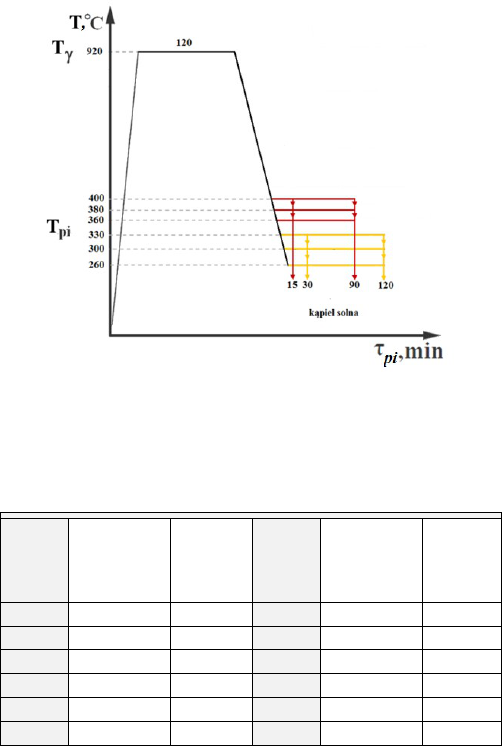
were austempered according to conditions presented in Table 2
and illustrated by diagram shown in Fig. 2.
The applied variants of austempering treatment and their
reference numbers are shown in Table 2.
Each single variant of the austenitizing and austempering
treatment included three test pieces prepared for the impact
test and three test pieces prepared for the tensile test. Heat
treatment was carried out in the Department of Ferrous Alloys
at the Foundry Research Institute in Cracow. Austenitizing
was made in a NABERTHERM Multitherm N41/M furnace
with a tight retort and a protective atmosphere of inert gas to
prevent decarburizing of the sample surface. Samples were
heated with the furnace to 920°C and held at that temperature
Fig. 1. TTT diagram of examined ductile cast iron
2275
for 2 h. A protective atmosphere of compressed argon was used
in the furnace.
Austempering (ausferritizing) was carried out in a salt
bath consisting of a mixture of potassium nitrate and sodium
nitrite. The salt bath temperature and isothermal cooling times
are shown in Table 2.
2.3. Microstructure of base ductile iron and ADI after
different variants of the austempering treatment
To reveal the microstructure of the test material, metallo-
graphic sections of both base ductile iron and ADI after differ-
ent heat treatment variants were prepared. The metallographic
sections of base cast iron and of cast iron after heat treatment
were etched in the Mi1Fe reagent according to PN-61/H-04503.
Selected metallographic sections of ADI were also etched in the
B-M reagent of the following chemical composition: 100 ml
of base solution (5 parts by volume of H
2
O, 1 part by volume
of concentrated HCl), 2 g of NH
4
F • HF, 1 g of K
2
S
2
O
5
. This
reagent does not dye austenite and carbides, while bainite and
tempered martensite are coloured in brown, and martensite is
coloured in blue. Sometimes fine martensite needles assume
not a blue but light brown colour, and if this is the case, then
the assessment of microstructure should be based on the studies
of its morphology.
Microstructure in both as-cast state and after heat treatment
was examined with an AXIO OBSERVER Z1M metallographic
microscope.
2.4. Testing of mechanical properties
Testing of mechanical properties included:
– static tensile test carried out at ambient temperature on an
Instron 8502 type testing machine. The cut out test pieces
were prepared in accordance with PN EN 1564. Tests con-
sisted in loading at a constant speed the samples mounted
in chucks of a hydraulic testing machine. The speed of the
tensile test was 0.02 mm/s. The elongation of the sample
was measured with an extensometer mounted on a measur-
ing section of the sample. During tensile tests, the instan-
taneous values of the loading force and elongation of the
sample were recorded. The tensile test was carried out until
the sample fracture. The parameters determined included
the tensile strength R
m
, yield strength R
p0.2
and elongation
A
5
. The results of the strength measurements were recorded
on three samples taken for a given heat treatment variant,
calculating next the mean values.
– measurement of the Charpy impact strength at ambient
temperature. The measurement of impact strength was
performed on 55x10x10mm samples V-notched to a depth
of 2 mm and with a fillet radius of 0.25 mm. To carry out
the tests, Charpy pendulum was used. The results of impact
test measurements were recorded on three samples taken for
a given heat treatment variant, calculating next the mean
values.
– Brinell hardness measurement. Brinell hardness measure-
ments were taken using an INNOVATEST/Nexus 703A
hardness tester. The test consisted in pressing a calibrated
D = 2.5 mm diameter ball into the polished surface of the
sample at a load of P = 187.5 kg. The operation time of full
pressure was 15 s. Hardness measurements were conducted
on samples broken in the impact test. For each variant,
15 Brinell hardness measurements were taken, calculating
next the mean.
3. Test results
3.1. As-cast microstructure
Images of as-cast ductile iron microstructure are shown
in Fig. 3. The microstructure is composed of metal matrix with
particles of spheroidal graphite distributed in this matrix. Most
of the graphite particles are surrounded by polygonal ferrite
grains. The metal matrix is formed of pearlite, inside which oc-
casionally occur ferrite grains and particles of non-metallic inclu-
sions.
Fig. 2. Variants of the austempering treatment
TABLE 2
Variants of the austempering treatment
Variant
Austempe-
ring
temperature
T
pi
[°C]
Austem-
pering
Time
τ
pi
[min]
Variant
Austempe-
ring
temperature
T
pi
[°C]
Austem-
pering
time
τ
pi
[min]
W11
400 15
W12
400 90
W9
380 15
W10
380 90
W7
360 15
W8
360 90
W5
330 30
W6
330 120
W3
300 30
W4
300 120
W1
260 30
W2
260 120

2276
3.2. Microstructure of ADI after different variants
of the austempering treatment
The photos of microstructure in Table 3 illustrate the effect
of the time and temperature of bainitic transformation on the ADI
matrix. As regards the temperature of the transformation, it is
clear that the higher is this temperature, the longer and thicker are
the “needles” of ferrite, and the higher is the austenite content,
reaching at 380-400°C even 30%. This type of ADI has a very
high ductility (Table 4). On the other hand, austempering in the
range of 260 – 300°C significantly increases both strength and
hardness of this material (Table 4). The austempering time of
15 minutes is definitely far too short and not used in practice.
In this study it was used only for cognitive reasons. The photos
of microstructure show that with the time of treatment so short,
complete bainitic transformation is not possible.
The austempering time of 90 minutes is applicable in the
case of austempering treatment ranging from 360 to 400°C,
while the time of 120 minutes (and longer) gives satisfactory
results when the treatment is carried out in the temperature range
of 260-300°C.
Both theory and practice show that this is related to the rate
of carbon diffusion, which at higher temperatures of the bainitic
transformation is proceeding more quickly, and more slowly at
lower temperatures.
It should be emphasized that studies were conducted on
samples of f 10 mm, tested for the mechanical strength. Castings
with thicker walls usually require longer times of austempering.
Fig. 3. As-cast microstructure of the tested cast iron
TABLE 3
Microstructure of material after different variants of the austempering treatment
Variant 1000× Variant 1000×
W11
T
pi
= 400°C,
τ
pi
= 15 min
nital
W12
T
pi
= 400°C, τ
pi
= 90 min
W9
T
pi
= 380°C,
τ
pi
= 15 min
nital
W10
T
pi
= 380°C,
τ
pi
= 90 min

2277
W7
T
pi
= 360°C,
τ
pi
= 15 min
B-M
W8
T
pi
= 360°C,
τ
pi
= 90 min
B-M
W5
T
pi
= 330°C,
τ
pi
= 30 min
nital
W6
T
pi
= 330°C,
τ
pi
= 120 min
W3
T
pi
= 300°C,
τ
pi
= 30 min
nital
W4
T
pi
= 300°C,
τ
pi
= 120 min
W1
T
pi
= 260°C,
τ
pi
= 30 min
nital
W2
T
pi
= 260°C,
τ
pi
= 120 min
3.3. The results of mechanical tests
3.3.1. Static tensile test
The following as-cast mechanical properties of the ductile
iron were obtained: the yield strength R
p0,2
= 478 MPa, the tensile
strength R
m
= 701 MPa and elongation A
5
= 6.9%.
Table 4 gives the results obtained in the static tensile test
carried out on specimens heat-treated according to the pro-
posed variants. The values given in Table 4 are the arithmetic
mean values calculated from the measurements taken on three
samples.
TABLE 3. CONTINUED

2278
TABLE 4
The results of mechanical tests
Variant A
5
, %
R
m
,
MPa
R
p0,2
,
MPa
Variant A
5
, %
R
m
,
MPa
R
p0,2
,
MPa
W11 1,8 868 595 W12 7,8 950 597
W9 1,8 810 675 W10 4,9 960 681
W7 1,3 952 757 W8 6,0 1068 783
W5 2,4 1201 779 W6 4,2 1255 968
W3 1,4 1065 835 W4 3,9 1381 1017
W1 1,1 737 W2 2,0 1343 1343
Fig. 4. ADI impact elongation vs the time and temperature of austem-
pering
Fig. 5. ADI tensile strength vs the time and temperature of austempe-
ring
Fig. 6. ADI yield strength vs the time and temperature of austempe-
ring
3.3.2. Hardness
As-cast hardness of the ductile iron was 202 HB. Table 5
gives the results of hardness measurements for samples heat
treated according to Figure 2 Austempering diagram. The results
are the mean calculated from the measurements taken on three
samples.
TABLE 5
The results of hardness measurements
Variant HB Variant HB
W11 292 W12 270
W9 369 W10 285
W7 401 W8 325
W5 375 W6 371
W3 437 W4 392
W1 523 W2 452
Fig. 7. ADI hardness vs the time and temperature of austempering
3.3.3. Impact strength
As-cast impact strength of the ductile iron was KCV =
4.2 J/cm
2
. The results of impact tests obtained on the heat treated
samples are shown in Table 6. For each variant, the mean was
calculated from the measurements taken on three samples.
TABLE 6
The results of impact tests
Variant KCV, J/cm
2
Variant KCV, J/cm
2
W11 4,8 W12 11,9
W9 3,8 W10 11,5
W7 3,4 W8 10,7
W5 6,3 W6 9,9
W3 5,5 W4 8,1
W1 2,4 W2 6,8
Fig. 8. ADI impact strength vs Austempering time and temperature
2279
4. Discussion
Base cast iron
The analysis of obtained results indicate that:
– the chemical composition of the base cast iron is typical
for pearlitic-ferritic ductile iron.
– pearlitic microstructure of the metal matrix and regular
precipitates of the spheroidal graphite were obtained,
– high values of the strength and ductility were obtained,
i.e. the yield strength R
p0,2
= 478 MPa, the tensile strength
R
m
= 701 MPa, elongation A
5
= 6.9%, Brinell hardness of
202 HB, the impact strength KCV = 4.2 J/cm
2
.
TTT diagram
To find correct parameters of the austempering treatment it
is necessary to plot a TTT diagram. A diagram like this, plotted
for the cast iron of the composition as demonstrated in Table 1,
is shown in Figure 1. From the diagram it follows that the hard-
enability to ausferrite is in this case inferior to the hardenability
obtained in the cast irons with two or three alloying elements.
Austempering
The adopted range of isothermal transformation was from
260 to 400°C at the time of austempering amounting to 15, 30,
90 and 120 minutes.
– ADI microstructure is shown in Table 4. There are clear
differences in the size of ferrite “needles” and in the austen-
ite content. The higher is the temperature of austempering,
the thicker are the “needles” and the higher is the content
of austenite.
– ADI strength achieves its peak values after austempering
at 260, 300 and 330°C, i.e. 1343, 1381 and 1255 MPa, re-
spectively, at the elongation A
5
equal to 2.0, 3.9 and 4.2%,
respectively. This corresponds to the ADI grade 1200-2
according to PN EN 1564,
– hardness – the results of Brinell hardness measurements
are given in Table 6. The highest values of hardness were
obtained in the cast iron austempered at 360°C (523 and
452 HB). This clearly indicates the presence of martensite
in the structure. The presence of this constituent in the
structure of ADI is disadvantageous, because it decreases
the ductility and may cause embrittlement, unless the target
is obtaining maximum abrasive wear resistance,
– impact strength, like the yield strength and elongation,
is a measure of the ADI ductility, and thus of its fracture
toughness. The results of these measurements are given in
Table 7. The highest values of this property were obtained
after austempering at 380°C (11.5 KCV) and 400°C (11.9
KCV). Yet, even after austempering at 300°C, the impact
strength of 8.1 KCV was obtained, which was a very sat-
isfactory result.
All of the above described properties are graphically de-
picted in the diagrams in (Figs. 6-10). Successive graphs illustrate
the effect of the time and temperature of austempering on the
tested mechanical properties.
5. Summary
Based on examinations results and their analysis several
conclusions were formulated:
– the conducted tests and studies have shown that ADI with
the addition of single alloying element, i.e. 1.5% Ni, can
produce only the grades 800-8 and 1200-2 (according to
PN EN 1624),
– optimum ausferritizing parameters for the grade 800-8 are
380°C at the time of 90 minutes,
– optimum ausferritizing parameters for the grade 1200-2 are
300°C at the time of 120 minutes,
– the austempering times of 15 and 30 minutes are definitely
too short,
– at the austempering temperature of 260°C, an ausferritic-
martensitic structure is obtained characterized by a hardness
of over 400 HB and high resistance to abrasive wear,
– ADI containing 1.5% Ni requires more detailed studies,
including fatigue strength and fracture toughness.
Acknowledgements
Financial assistance of the NCN, project No. 2013/11/N/ST8/00326
REFERENCES
[1] C. Podrzucki, Problemy produkcji odlewów z żeliwa sferoidalnego
ADI. Przegląd Odlewnictwa 10, 260-265 (1996).
[2] Multiple advantages of austempered ductile iron. ADI being
chosen over aluminum. Modern Casting 9, 15-16 (1999).
[3] J.F. Janowak, P.A. Morton, A guide to mechanical properties possi-
ble by austempered 1,5% Ni-0,3% Mo ductile iron. Transactions
AFS, 489-498 (1984).
[4] M. Grech, J.M. Young, Impact properties of a Cu-Ni austempered
ductile iron. Cast Metals 1/2, 98,(1988).
[5] A. Kowalski, J. Tybulczuk, Experience of The Foundry Research
Institute Krakow in investigation and application of Ni-Cu ADI for
castings. 42 Livarsko Strokovno Posvetovanje. Slovenja, Portoroż
23-24 May 2002, (2002).
[6] R.H. Juneja, et al., Austempering ductile iron alloyed with coper
and manganese, Foundry 64, (1989).
[7] E. Dorazil, Zwischenstufenumwandeln von Gusseisen mit Kugel-
graphit, Giesserei-Praxis 18, 355 (1979).
[8] K.L. Hayrynen, The production of austempered ductile iron (ADI).
World Conference of ADI. Livonia, Michigan, USA, (2002).
[9] A. Owhadi, et al., Wear behavior of 1.5 Mn austempered ductile
iron, Materials Science and Technology 14, 245 (1998).
[10] M.N. Ahamadabadi, E. Niyama, T. Ohide, Structural control of
1% Mn ADI aided by modeling of microsegregation, Transactions
AFS, 269 (1994).
[11] Z. Pirowski, et al., Wpływ mikrododatku boru na zmiany har-
towności w żeliwie sferoidalnym z przemianą izotermiczną
w odniesieniu do odlewów grubościennych, Journal of Research
2280
and Applications in Agricultural Engineering 57 (2), 153-155,
(2012).
[12] S. Kluska-Nawarecka, D. Wilk-Kołodziejczyk, K. Regulski, et al.,
Rough Sets Applied to the Rough Cast System for Steel Castings,
Lecture Notes in Artificial Intelligence 6592, 52-61 (2011).
[13] B. Sniezynski, G. Legien, D. Wilk-Kolodziejczyk, et al., Creative
Expert System: Result of Inference and Machine Learning Integra-
tion, Lecture Notes in Computer Science 9827, 257-271 (2016).
[14] D. Wilk-Kolodziejczyk, B. Mrzyglod, K. Regulski, et al., Influence
of process parameters on the properties of austempered ductile iron
(adi) examined with the use of data mining methods, Metalurgija
55 (4), 849-851 (2016).
[15] I. Olejarczyk-Wozenska, H. Adrian, B. Mrzygłód, et al., Numerical
modelling of austenite-ferrite transformation in ADI, METAL
2015: 24th International Conference on Metallurgy And Materials,
810-815 (2015).
