
InstallationManual
For
HighSpeed
AlumavatorandPlatinum
10and23Degree
ElevatorBoatLifts

Page|2
17030AlicoCenterRd.,FortMyers,FL339671‐800‐545‐5603 www.iqboatlifts.com
SafetyPrecautions
1. Your boat lift is a heavy duty piece of
equipment.Itisimportantthatallpersons
that may operate this unit have read and
understoodtheowner’smanual.Giventhe
inherent dangers of heavy machinery, your
boat lift deserves respect, and good
judgmentisrequiredinitsoperation.Before
allowing
others to operate the unit be
certain that they understand the proper
operatingprocedures.Donotallowchildren
tooperatethelift.
2. Thisproductisforlifting unoccupiedboats.
Donotrideinyourboatorontheliftduring
operation.Alwaysattendthecontrolswhen
operating the lift,
and watch carefully to
have others stand clear.Keep hands, feet,
andclothingawayfromallmovingparts.
3. Yourliftisoperatedbyelectricity,therefore,
additional care must be taken.It must be
wired by a licensed electrician, and it must
be installed with an approved ground fault
interruption
device.Ifyouobservesevered
or damaged wiring, it must be repaired
immediately by an electrician.When
properlyinstalledandmaintained,electrical
devicessuchasthisliftarecompletelysafe.
However, any electrical device used in and
around a water environment must be
treated with great respect to prevent
accidental
electrocution.All electrical
maintenanceandservicetothisliftmustbe
donebyalicensedelectrician.
4. Whileoperatingyourlift,routinelylookatall
cables for fraying, damaged ends, or loose
strands.Adamagedcablemustbereplaced
immediately.Makesurethatallpulleysare
turningproperly.Routinelylook
overcables
tomakesurethattheyarewindingproperly.
Lookforsignsofextremewearandunusual
corrosion, as well as, exposed or damaged
electricalwires.Ifyoufindanyoftheabove,
havetheproblemrepairedimmediately.
5. Do not work on your boat or lift while the
boatishoisted.Whenworkingonyourlift,
keep your hands, feet, and clothing away
fromallmovingparts.Exercisegreatcareif
chainsor gearing areexposed.Neverwork
underneatharaisedlift,anddonotwalkor
stand on a raised lift.Always disconnect
electrical power when working on
any part
ofthelift.
6. Becarefulnot to exceed the rated capacity
ofthelift.Todeterminethetotalweightof
yourequipmenttobelifted,studytheboat
manufacturer's literature to determine its
weight.Besuretoaddenoughextraweight
to compensate for your added accessories,
including water and fuel.Gasoline weighs
about 6 lbs. per gallon and water weighs
about8lbs.pergallon.
7. If you plan to leave your lifted boat
unattendedforseveralweeks,itisimportant
thatyou remove the drainplug in the boat
to prevent it from filling with
rain water.
Accumulated rain, snow or other water in
yourboatcanrapidlybecomeheavyenough
to exceed the capacity of a lift, causing
personal injury or damage to the boat and
lift.

Page|3
17030AlicoCenterRd.,FortMyers,FL339671‐800‐545‐5603 www.iqboatlifts.com
PartsList
1. GuidePostAssembly13.BoltHXHD¾”x10”UNC
2. BunkandCoverAssembly 14.Washer,Flat¾”
3. ElevatorArm15.NylockNut,¾”UNC
4. I‐BeamTrack16.BoltHXHD⅜”x4”UNC
5. Piling17.Washer,Flat⅜”
6. TelescopicBrace18.NylockNut,⅜”UNC
7. PileMountBracket19.TelescopicMount,InsideTube
8. TrackMountandTrackClamp 20.BoltHXHD½”‐13x4”UNC
9. Powerhead21.Nut,HXHD½”‐13UNC
10. BoltHXHD½”x2½”UNC
11. Washer,Flat½”
12. NylockNut,½”UNC

Page|4
17030AlicoCenterRd.,FortMyers,FL339671‐800‐545‐5603 www.iqboatlifts.com
Introduction
Welcome,andcongratulationsonyourpurchaseofanImmQualityBoatLift!AtImm
QualityBoatLifts,wetakeprideinmakingthemostadvanced,mostdurable,easytouseand
lowmaintenanceboatliftsonthemarkettoday.Theinstallationofthisliftissimplifiedbyits’
lightweightaluminumconstructionandbyextensivefactoryassembly.OnlyImmQualitytakes
theextratimetopre‐windthecableonthewinders,pre‐assemblethedrives,motors,covers
andpowerheadcomponents,andpre‐assemblethecarriageincludingbunkbracketsandguide
postassembly.Wedoallthisasanaddedservicetomakelifeeasierforourvaluable
customers.Inthefollowingpages,wewilltakeyoustep‐by‐stepthroughtheentireinstallation
process.Weurgeyoutoreadthismanualbeforeattemptinginstallation.Ifyouhaveany
questions,pleasecontactusat1‐800‐545‐5603andaskfortechnicalsupport.
Beforeyoubegin…
Ourelevatorliftscanbemountedtowoodpilings,concretepilings,concretedocksor
seawalls.Thepilings,docksorseawallsarethefoundationoftheboatliftandmustbeableto
carrythecombinedloadoftheliftandthefullyloadedboat.LocalandNationalbuildingcode
andcommonpracticevariesfromareatoarea.Consultwithourtechnicalservicedepartment
oryourlocalmarinecontractorforappropriateguidelines.Itisthecontractor’s/installer’s
responsibilitytodetermineandconstructsuitablesupportstructureandbracingforour
elevatorlifts.

Page|5
17030AlicoCenterRd.,FortMyers,FL339671‐800‐545‐5603 www.iqboatlifts.com
HiSpeedElevatorLiftElectricalRequirements
Havingtheproperelectricalservicetotheboatliftiscriticaltotheperformanceofthe
lift.Inadequateelectricalservicecouldresultindamagetothemotorand/ortheliftcontrols.
Whenatallpossible,theboatliftshouldhavededicatedelectricalservicetopreventcircuit
overloadingandtominimizeinterferencebyotherdevicesonthecircuit.Consultthefollowing
chartasminimumguidelinesforproperlysizedcircuitbreakerandwiresizebasedon
horsepower,numberofmotorsandbrakeelectricalrequirements.
MinimumBreakerand75CCopperWireSize(AWG)forSingle‐PhaseA.C.Motors
ImportantNotes:
Pleaseusecurrentmotorlabeltoconfirmspecificationsinabovechart.
ForAluminumwire,increaseby1wiresize,minimum.
Theappropriateinstructionsandwiringdiagramsareenclosedinthecontrolbox.
Thewiringrecommendationsanddiagramsreferredtoarenotmeanttosupersedeanynational
orlocalcodes.
Readallinstructionsandwiringdiagramsbeforeconnectingorchangingwires.
ImmQualityBoatLiftsrecommendsthatallelectricalworkbeperformedbyalicensedelectrical
contractor.
WiringproceduresotherthanthosepresentedbyImmQualityBoatLiftswillvoidtheproduct
warranty.
AFOURPOLEDISCONNECTOREQUIVALENTCONTROLBOXMUSTBEINSTALLED.An
electrochemicalreactionknownaselectrolysiscancauseprematuredegradationofmetal
componentsincludingbutnotlimitedtoI‐beamtracksandcarriage.Theliftselectricalsupply
(includinggroundandneutrallegs)shouldbemechanicallydisconnectedfromthepowersource
whennotinuse.
WIREDZINCSMUSTBECONNECTEDTOTHELIFTANDALWAYSBESUSPENDEDUNDERWATER.
Werecommendwrappingthewireofthezincaroundamountingbolt(betweenwasherand
mountingsurface)onthetelescopictrackmountoneachtrack.Twozincsareprovidedwiththe
lift.Zincsmustbecheckedperiodicallyand
replacedasnecessary.
#andMotor
H.P.
Ampstorun BreakerSize 50Feet 100feet 200feet 300feet 400feet
115V 230V 115V 230V 115V 230V 115V 230V 115V 230V 115V 230V 115V 230V
(2)11/2H.P. ‐‐‐‐ 22 ‐‐‐‐ 30A ‐‐‐‐ #10 ‐‐‐‐ #8 ‐‐‐‐ #6 ‐‐‐‐ #4 ‐‐‐‐ #3
(2)2H.P. ‐‐‐‐ 25 ‐‐‐‐ 35A ‐‐‐‐ #10 ‐‐‐‐ #8 ‐‐‐‐ #4 ‐‐‐‐ #4 ‐‐‐‐ #3
(2)3H.P. ‐‐‐‐ 38 ‐‐‐‐ 50A ‐‐‐‐ #6 ‐‐‐‐ #6 ‐‐‐‐ #4 ‐‐‐‐ #3 ‐‐‐‐ #2

Page|6
17030AlicoCenterRd.,FortMyers,FL339671‐800‐545‐5603 www.iqboatlifts.com
GeneralInstallationNotes:
Standardpilingspacingrangesfrom9’to11’dependingonliftcapacity,boatandlocal
conditions.Consulttheliftspecificationsheettoseeourrecommendationbasedonthe
capacityofthelift.Ultimately,itisthecontractor’s/installer’sresponsibilitytodetermineand
setthespacingandheightofthepiling.Togetthekeeloftheboattoalignwiththedeck
height,thetrackmustbeatleast52”forthe4,500,60”forthe8,000and10,000and64”above
thedeckforthe13,000poundandlargercapacitylifts(measuredverticallyfromdeckto
highestpointofthetrack).
Standardtravelis12’onthe4,500,8,000,and10,000poundcapacityelevatorliftsand
11’onthe13,500,16,000and20,000poundcapacityelevatorlifts.Standardtracklengthis25’
forallcapacities.Note:Waterdepthandbottomconditionsmayrequiretheuseoflonger
tracks.

Page|7
17030AlicoCenterRd.,FortMyers,FL339671‐800‐545‐5603 www.iqboatlifts.com
TrackInstallConsiderations
CarriageHeight:
42”on4.5K
48”on8and10K
52”on13,16and20K
PowerheadRequires:
5”oftrackfor
mountingon4.5,8
and10Klifts.
6”oftrackfor
mountingon13,16
and20Klifts.
PilingMount:
Topofmounting
bracketmustbe6”
belowtopofpile.
Note:Ifdistance
fromrefusaltopiling
mountismorethan
15’,trackbracingis
required.See
instructionsprovided
withbracesfor
installation.
LiftSpecifications
StandardTravel: 12’for4.5,8and10Kcapacities
11’for13.5,16,and20Kcapacities
ExtendedTravel: 15’for10K,16’for20Kcapacities
20’for4.5,8,13and16Kcapacities
MaxRaisedPosition:30”fromtopofthetrack(toallowforpowerheadandmount)
TrackAngle:10or23degrees
StandardTrackLength:25’

Page|8
17030AlicoCenterRd.,FortMyers,FL339671‐800‐545‐5603 www.iqboatlifts.com
WillitFit?
Therearetwoimportantmeasurementstoconsiderwhendeterminingthepropersize
ofelevatorliftforyourboatandinstallationlocation:thecarriagearmlengthandthedistance
fromtheendofthecarriagearmtothepile.Thedistancefrompilemeasurementisoften
importanttoknowforpermitting,wherelocalordinancemayrestrictthedistanceyourboatlift
structureprotrudesintothechannel.Thecarriagearmlengthisimportanttoknowwhen
decidingifyourboatwillfitcomfortablyonthelift.Pleaseconsultthefollowingtableand
formulawhileyouareplanningyourinstallation.Custombuiltelevatorliftsareavailableto
accommodateanysizeorshapeofboat.
Havingyourtrackinstalledatanangle
slightlycomplicatesthedistancefrompile
measurementbecausethefartherdown
thepileyoutakeyourmeasurement,the
trackwillbefartheroutfromthepile.
Youcaneasilycalculatethedistancethe
trackisawayfromthepileusingthe
followingequation:
B↔C=tan(∠)*A↔B
Forexample,ifyouhaveinstalledyour
trackat23°andwanttomeasurethe
distancethetrackisawayfromthepile
(B↔C)at120”belowpointA(A↔B),
thecalculationwouldbe:
B↔C=tan(23)*120
Therefore,B↔C=51”
Onthefollowingpagewehaveprovidedatableshowingcarriagemeasurementsforour
standardelevatorliftcapacitiesthatwerebuilttobeinstalledateither10°or23°.To
determinethedistancefromthepile,yousimplyaddthedistancethetrackisawayfromthe
pile(B↔C)tothecarriagewidthandarmlength,bothofwhichcanbefoundinthefollowing
table.
∠=angleofinstallation
A=pointwherepilewould
intersectthetrack
B=distancedownthepile
C=pointwhereahorizontalline
fromBwouldintersectthetrack

Page|9
17030AlicoCenterRd.,FortMyers,FL339671‐800‐545‐5603 www.iqboatlifts.com
TableofCarriageMeasurements
DistanceFromPile=B↔C+ArmLength+CarriageWidth
Forexample,ifyouhavea16,000lbs.capacityelevatorliftandyouhaveinstalledyour
trackat23°andwanttomeasurethedistancefromthepileat120”belowpointA(A↔B),the
calculationwouldbe:
DistanceFromPile=B↔C+ArmLength+CarriageWidth
DistanceFromPile=51+108+29.25
DistanceFromPile=188.25”
LiftCapacity ArmLength CarriageWidth MaxBeamofBoat*
4,500 86.5” 17” 114”
8,000&10,000 100.75” 23.25” 126”
13,500&16,000 108” 27.25 138”
20,000 132” 33.75” 150”
4,500 86.5” 18.5” 120”
8,000&10,000 102” 25.75” 132”
13,500&16,000 108” 29.25” 144”
20,000 132” 35.25” 156”
10°23°
*MaxBeammeasurementforaliftloadedtofullca
p
acit
y

Page|10
17030AlicoCenterRd.,FortMyers,FL339671‐800‐545‐5603 www.iqboatlifts.com
SeawallMountInstallation
1) Thepositioningoftheseawallmountbracketontheseawallcapisultimatelyuptothe
installer/contractor.Theseawallmountbracketbasecanbeflushwiththeseawallcap
withangledtrackinstallations.Verticaltrackinstallationsrequiretheedgeofthe
seawallmountbrackettoprotrudeatleast1”intotheslipareatoaccommodatethe
trackclampbolts.Forallinstallations,makesurethetrackwillcleartheseawallcap
beforeanchoringthemountingbracket.
2) Theseawallmountbrackethasthreeholesforanchoringtotheseawallcap.Theholes
are7/8”diameter.Thetypeofanchoringhardwareandtheirsuitabilityisleftuptothe
installer/contractortodetermineandsupply.

Page|11
17030AlicoCenterRd.,FortMyers,FL339671‐800‐545‐5603 www.iqboatlifts.com
PileMountInstallation
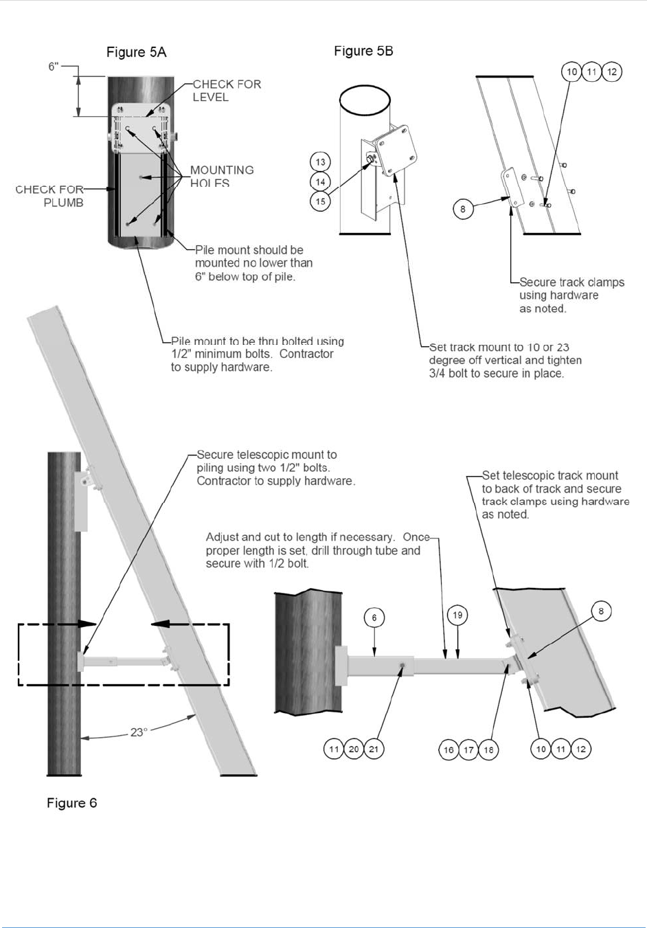
**Pleaserefertofiguresonpage12forinstallingthepilingmountassemblies.**
Thetopofthepilemountbracketshouldbe6”fromthetopofthepiling.Thepile
mountbracketmustbelevelandplumb.(Figure5A)
Thepilemountbracketshouldbeattachedtothepileusingfive½”diametercarriage
boltsorthreadedrod(ContractorSupplied).Theuseoflagscrewswillvoidthe
warranty.Installboltsthrupilingandsecureusingbackingwashersandnuts
(ContractorSupplied).
(Figure5B)Usingalevelandananglefinder,setthetrackmountbrackettotheinstall
angle(either10or23degreesoffvertical)andtightenthe¾”bolt(parts13,14and15).
TrackInstallation
**Pleaserefertofiguresonpage12forinstallingthetracks.**
(Figure5B)Usingthetrackmountclamps(part8)with½”x2½”boltsandhardware
(parts10,11and12),looselybolttracktopilingorseawallmount.Verifycorrect
alignmentoftrackanddrivetracktorefusal(thepointatwhich10impactsofatrack
driverdoesnotmovethetrackfartherthan¼”).Thebracketfacemaybeusedasa
guidewhiledrivingthetrack,butthecontractormustfrequentlyverifythealignment
duringtheinstallationprocess.
Oncetrackissetinplace,checkforcorrectalignmentonemoretime.Tightenallbolts
ontheclampstosecurethetrack.
Repeattheabovestepsforthesecondtrackandmountassembly.Takespecialcareto
ensurethatthesecondtrackisbothplumbandparallelwiththefirsttrack.To
accomplishthis,makesuretheangleofinstallationisthesameforbothtracksandthat
thedistancebetweenthetwotracksisequalatboththetopandbottomofthetracks.
(Figure6)Installthetelescopictrackbrace(part6)tothepilingorseawall.Measure
thedistancefromtheendofthebracetothetrackonahorizontalplane.Ifneeded,cut
theopposingtelescopicmountinsidetube(part19)sothatitwillslideintothemounted
endandengageatleast2”beyondtheconnectinghole.Onceproperlengthisset,drill
throughtubeandsecurewith½”boltandhardware(parts11,20and21).
Securethetelescopicarmbrackettothetrackwithtrackmountclampsandhardware
(parts8,10,11,12,16,17and18).Remembertowrapthewireofthezincsaroundthe
mountingboltsbetweenthewasherandtrackclamp.
Thedistancebetweenthepilingmountandthetelescopicmountshouldbeatleast30”.
Thebraceshouldbemountedasclosetothehighwaterlineaspossiblewithoutbeing
mountedinthewater.
Page|12
17030AlicoCenterRd.,FortMyers,FL339671‐800‐545‐5603 www.iqboatlifts.com

Page|13
17030AlicoCenterRd.,FortMyers,FL339671‐800‐545‐5603 www.iqboatlifts.com
InstallingCarriageArmsandPowerHead
Removetheupperwheelplatefromonesideofthecarriage.
PositioncarriagesothatlowerwheelridesontheflangefaceoftheI‐beamtrackthatis
closesttothesliparea.
Leanthecarriagearmbacksothattheupperwheelsengageandrideontheopposite
faceoftheI‐beamtrack.
Re‐installtheupperwheelplateandtightenallhardware.
ToinstallPowerHead,simplyslidethemountbaseoverthetopofthetrackandlower
untilitbottomsout.Tightenthefourclampboltstosecure.

Page|14
17030AlicoCenterRd.,FortMyers,FL339671‐800‐545‐5603 www.iqboatlifts.com
Electrical:MotorWiringforHiSpeedLifts
Themotorandbrakeareprewiredatthefactoryfor240VAC.Thepowerheadcoverdoesnot
needtoberemovedtowirefor240VACtoacontrolbox.Allmotorwireleadshavebeen
routedtoaconduitboxlocatedonthebackplateofthepowerheadenclosure.Toconnectto
theBonita,GemorTigersharkcontrolboxes,simplyconnectthemotorwireleadstothelike
colorwiresfromthecontrolbox(ie.orangetoorange).
Allmotorwiresarelocatedinsidethisconduitbox.
**Note:ImmQualityBoatLiftsrecommendsthatthe
electricalhookupbeperformedbyalicensed
electricianandconformstoallnationalandlocal
electricalcode.Theappropriatewiringdiagramand
furtherinstructionsareenclosedbytheOEMinthe
controlbox.Pleasereadallinstructionsandwiring
diagramsbeforeconnectingorchanginganywires.**
Ifyouneedtowiretheliftfor120VAC,themotorandbrakewillhavetoberewired.Inorder
toaccessthemotorandbrake,removethepowerheadcover.Openthemakeupboxattached
tothemotorandfollowtheappropriatewiringdiagramandinstructionsthatareenclosedby
theOEMinthecontrolbox.Pleasereadallinstructionsandwiringdiagramsbeforeconnecting
orchanginganywires.Foryourconvenience,the240VoltwiringdiagramsfortheAlumavator
andPlatinumliftsareshownbelow.
Alumavator240Volt Platinum240Volt
Page|15
17030AlicoCenterRd.,FortMyers,FL339671‐800‐545‐5603 www.iqboatlifts.com
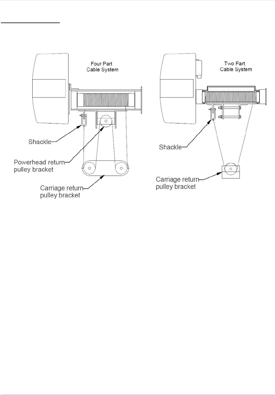
InstallingCable
The4,500‐10,000poundcapacityliftshavetwopartcablesystems.The13,000pound
andhighercapacityliftshavefourpartcablesystems.Tofacilitateinstallation,thecablecomes
pre‐woundonthewinder.Routethecablesasshowninthefiguresabove.
1) Removethe¾”bolt(s)thatfunctionsastheaxle(s)forthepulleys.
2) Routethecablesandre‐installthepulleyswiththebolts.
3) Makesuretherearenoloops,kinksortwistsinthecable.
4) Attachthethimbleendofthecabletotheshackle.
5) Securelytightentheshacklepin.

Page|16
17030AlicoCenterRd.,FortMyers,FL339671‐800‐545‐5603 www.iqboatlifts.com
BunkBoardandGuidePostInstallation
WOODENBUNKS
∙Thebunkbracketshavebeenpre‐installedonthe
carriageI‐beams.Thebracketsmayberepositioned
bylooseningthenutsatthebracketandslidingalong
thebeam.
∙Centerthebunkboardsonthecarriagearms.
∙Makesurethebunkboardsareflushtothecarriage
armsandthebunkbrackets.
∙Mark,thendrill(8)½”diameterholesformounting
thebunkboardstothebunkbrackets.
∙Attachthebunkboardswiththesuppliedstainless
steelboltsandhardware.
ALUMINUMBUNKS
∙Thebunkbracketsmaybe
installedverticallyoratan
angleof20°.
∙Tightenboltstoclamp
bracketstocarriagearm.
∙Toattachaluminumbunks,
firstslidethemoverthetop
ofthebrackets.
∙Refertofigureforlocation
ofholes.Mark,thendrill
holesthroughbunksto
matchexistingholesinthe
anglebrackets.
∙Attachwith½”‐13x4”
boltswithhexnutinsideand
flangednutontheoutside
GUIDEPOSTASSEMBLY
∙Theguidepostbracketscomepre‐installedonthecarriagearms.Thebracketsmaybe
repositionedbylooseningthenutsontheclampsandslidingalongthecarriageI‐beam.
∙InstallguidepostpipeinsertintothebracketsandslidePVCprotectivesleeveoverthepipe.
∙Withboatpositionedonthelift,makefinaladjustmentstothefitoftheguidepostsandthen
tightenbrackethardware.

Page|17
17030AlicoCenterRd.,FortMyers,FL339671‐800‐545‐5603 www.iqboatlifts.com
ImmQualityBoatLiftsContactInformation
Phone:(239)432‐9110
TollFree:800‐545‐5603
Fax:(239)432‐0019
Website:iqboatlifts.com
Sales:
GeneralInquiries:inf[email protected]
