
Facilities Management
5/16/2024
Design GUIDELINES

Design Guidelines Facilities Management
i
Contents
PREFACE vii
Change Log viii
Definitions xi
Procurement & Contracting ........................................................................................................... 00-1
00 10 00 Solicitation/Bid Advertisement .................................................................................................. 00-1
00 21 00 Instructions to Bidders ............................................................................................................... 00-1
00 31 31 Geophysical Data ....................................................................................................................... 00-1
00 45 13 Bidder Qualifications .................................................................................................................. 00-1
00 72 00 General Conditions of the Contract ............................................................................................. 00-1
General Requirements ................................................................................................................... 01-1
01 00 00 General Project/Design Requirements ........................................................................................ 01-1
01 14 00 Work Restrictions (Site Access, Occupant Coordination, Site Use)................................................ 01-4
01 20 00 Change Order Procedures........................................................................................................... 01-4
01 31 00 Coordination .............................................................................................................................. 01-4
01 33 00 Submittals ................................................................................................................................. 01-5
01 35 00 Special Project Procedures ......................................................................................................... 01-5
01 51 00 Temporary Utilities .................................................................................................................... 01-6
01 52 00 Construction Facilities ................................................................................................................ 01-6
01 55 00 Vehicular Access and Parking ..................................................................................................... 01-7
01 56 00 Temporary Barriers and Enclosures ............................................................................................ 01-7
01 56 39 Temporary Tree and Plant Protection ......................................................................................... 01-8
01 57 00 Temporary Controls ................................................................................................................... 01-8
01 60 00 Product Requirements ............................................................................................................... 01-8
01 73 00 Execution ................................................................................................................................... 01-9
01 74 00 Cleaning and Waste Management .............................................................................................. 01-9
01 77 00 Closeout Procedures .................................................................................................................. 01-9
01 78 00 Closeout Submittals ................................................................................................................... 01-9
01 78 23 Operation and Maintenance Data ............................................................................................ 01-10
01 78 36 Warranties............................................................................................................................... 01-10
01 78 44 Extra Stock Materials ............................................................................................................... 01-11
01 79 00 Demonstration and Training ..................................................................................................... 01-11
01 80 00 Performance Requirements ...................................................................................................... 01-11
01 81 00 Facility Performance Requirements (Alternate) ........................................................................ 01-11
Site Construction ........................................................................................................................... 02-1
02 30 00 Subsurface Investigation ............................................................................................................ 02-1
02 40 00 Demolition and Structure Moving ............................................................................................... 02-1
Concrete ....................................................................................................................................... 03-1

Design Guidelines Facilities Management
ii
03 05 00 Common Work Results for Concrete ........................................................................................... 03-1
03 10 00 Concrete Forming ...................................................................................................................... 03-1
03 15 00 Concrete Accessories ................................................................................................................. 03-1
03 20 00 Concrete Reinforcing .................................................................................................................. 03-1
03 30 00 Cast-In-Place Concrete ............................................................................................................... 03-1
03 35 00 Concrete Finishing...................................................................................................................... 03-2
03 35 11 Concrete Floor Finishes .............................................................................................................. 03-2
03 39 00 Concrete Curing ......................................................................................................................... 03-5
Masonry........................................................................................................................................ 04-1
04 05 00 Common Work for Masonry ....................................................................................................... 04-1
Metals .......................................................................................................................................... 05-1
05 40 00 Cold Formed Metal Framing ....................................................................................................... 05-1
05 50 00 Metal Fabrications ..................................................................................................................... 05-1
Wood, Plastics, and Composites ..................................................................................................... 06-1
06 10 00 Rough Carpentry ........................................................................................................................ 06-1
06 41 00 Architectural Wood Casework .................................................................................................... 06-1
Thermal & Moisture Protection ..................................................................................................... 07-1
07 05 00 Common Work Results for Thermal & Moisture Protection ......................................................... 07-1
07 10 00 Dampproofing and Waterproofing.............................................................................................. 07-1
07 21 00 Thermal Insulation ..................................................................................................................... 07-1
07 26 00 Vapor Retarders ......................................................................................................................... 07-1
07 50 00 Membrane Roofing .................................................................................................................... 07-1
07 60 00 Flashing and Sheet Metal ........................................................................................................... 07-2
07 70 00 Roof and Wall Specialties and Accessories .................................................................................. 07-2
07 90 00 Joint Protection ......................................................................................................................... 07-2
Openings (Doors & Windows) ........................................................................................................ 08-1
08 05 00 Common Work Results for Openings .......................................................................................... 08-1
08 10 00 Doors and Frames ...................................................................................................................... 08-1
08 11 13 Hollow Metal Doors and Frames................................................................................................. 08-1
08 11 16 Aluminum Doors and Frames ..................................................................................................... 08-3
08 31 00 Access Doors and Panels ............................................................................................................ 08-4
08 50 00 Windows ................................................................................................................................... 08-4
08 70 00 Hardware .................................................................................................................................. 08-5
Finishes ......................................................................................................................................... 09-1
09 05 00 Common Work Results for Finishes ............................................................................................ 09-1
09 20 00 Plaster and Gypsum Board ......................................................................................................... 09-1
09 51 00 Acoustical Ceilings ..................................................................................................................... 09-1
09 60 00 Flooring ..................................................................................................................................... 09-1

Design Guidelines Facilities Management
iii
09 68 00 Carpet ....................................................................................................................................... 09-1
09 70 00 Wall Finishes .............................................................................................................................. 09-2
09 90 00 Painting and Coating .................................................................................................................. 09-2
Specialties ..................................................................................................................................... 10-1
10 11 00 Visual Display Surfaces ............................................................................................................... 10-1
10 13 00 Directories ................................................................................................................................. 10-1
10 14 00 Signage ...................................................................................................................................... 10-1
10 28 00 Toilet and Bath Accessories ........................................................................................................ 10-1
Equipment .................................................................................................................................... 11-1
11 21 23 Vending Equipment ................................................................................................................... 11-1
11 52 13 Projection Screens ..................................................................................................................... 11-1
Furnishings .................................................................................................................................... 12-1
12 20 00 Window Treatment .................................................................................................................... 12-1
12 30 00 Manufactured Casework ............................................................................................................ 12-1
12 31 00 Manufactured Metal Casework .................................................................................................. 12-1
12 36 00 Countertops ............................................................................................................................... 12-9
12 50 00 Furniture ................................................................................................................................... 12-9
12 60 00 Multiple Seating ........................................................................................................................ 12-9
12 93 13 Bicycle Racks ............................................................................................................................ 12-10
Special Construction ...................................................................................................................... 13-1
Conveying Systems ........................................................................................................................ 14-1
14 20 00 Elevators ................................................................................................................................... 14-1
14 40 00 Lifts ........................................................................................................................................... 14-1
Reserved ....................................................................................................................................... 15-1
Reserved ....................................................................................................................................... 16-1
Reserved ....................................................................................................................................... 17-1
Reserved ....................................................................................................................................... 18-1
Reserved ....................................................................................................................................... 19-1
Reserved ....................................................................................................................................... 20-1
Fire Suppression ............................................................................................................................ 21-1
21 05 00 Common Work Results for Fire Suppression ............................................................................... 21-1
21 10 00 Fire Protection System Impairment Procedure ............................................................................ 21-1
Plumbing ....................................................................................................................................... 22-1
22 05 00 Common Work Results for Plumbing .......................................................................................... 22-1
22 05 53 Identification for Plumbing Piping and Equipment ...................................................................... 22-1
22 07 00 Plumbing Insulation ................................................................................................................... 22-2
22 07 16 Plumbing Equipment Insulation .................................................................................................. 22-2
22 07 19 Plumbing Piping Insulation ......................................................................................................... 22-2
22 10 00 Plumbing Piping and Pumps ....................................................................................................... 22-4
22 14 00 Facility Storm Drainage .............................................................................................................. 22-5

Design Guidelines Facilities Management
iv
22 30 00 Plumbing Equipment .................................................................................................................. 22-5
22 40 00 Plumbing Fixtures ...................................................................................................................... 22-5
Heating, Ventilating, and Air Conditioning ...................................................................................... 23-1
23 05 00 Common Work Results for HVAC ................................................................................................ 23-1
23 07 00 HVAC Insulation ......................................................................................................................... 23-2
23 07 13 Duct Insulation .......................................................................................................................... 23-2
23 07 16 Equipment Insulation ................................................................................................................. 23-3
23 07 19 HVAC Piping Insulation ............................................................................................................... 23-4
23 09 00 Instrumentation and Control for HVAC ....................................................................................... 23-6
23 20 00 HVAC Piping and Pumps ............................................................................................................. 23-6
23 22 01 Underground Steam and Condensate Distribution System .......................................................... 23-7
23 22 02 Steam and Condensate Piping and Pumps within buildings ......................................................... 23-9
23 23 00 Refrigerant Piping .................................................................................................................... 23-10
23 30 00 HVAC Air Distribution ............................................................................................................... 23-10
23 40 00 HVAC Air Cleaning Devices ....................................................................................................... 23-10
23 25 00 HVAC Water Treatment ............................................................................................................ 23-11
23 60 00 Central Cooling Equipment ....................................................................................................... 23-11
23 81 26 VRV Air Conditioners ................................................................................................................ 23-11
Reserved ....................................................................................................................................... 24-1
Integrated Automation .................................................................................................................. 25-1
Electrical ....................................................................................................................................... 26-1
26 05 00 Common Work Results for Electrical ........................................................................................... 26-1
26 10 00 High-Voltage Electrical Distribution ............................................................................................ 26-2
26 20 00 Electrical Distribution ................................................................................................................. 26-2
26 32 00 Packaged Generator Assemblies ................................................................................................. 26-2
26 50 00 Lighting ..................................................................................................................................... 26-2
Communications ........................................................................................................................... 27-1
27 10 00 Structured Cabling ..................................................................................................................... 27-1
27 10 05 Telecommunications Cabling ...................................................................................................... 27-7
27 50 00 Distributed Communications and Monitoring Systems .............................................................. 27-17
Electronic Safety and Security ........................................................................................................ 28-1
28 10 00 Electronic Access Control and Intrusion Detection ...................................................................... 28-1
28 30 00 Electronic Detection and Alarm .................................................................................................. 28-1
Reserved ....................................................................................................................................... 29-1
Reserved ....................................................................................................................................... 30-1
Earthwork ..................................................................................................................................... 31-1
31 14 00 Earth Stripping and Stockpiling ................................................................................................... 31-1
31 22 00 Grading ..................................................................................................................................... 31-1
31 23 00 Excavation and Fill ..................................................................................................................... 31-1
Design Guidelines Facilities Management
v
Exterior Improvements .................................................................................................................. 32-1
32 05 00 Common Work Results for Exterior Improvements ..................................................................... 32-1
32 11 00 Base Courses .............................................................................................................................. 32-1
32 14 00 Unit Paving ................................................................................................................................ 32-1
32 32 00 Retaining Walls .......................................................................................................................... 32-1
32 80 00 Irrigation ................................................................................................................................... 32-1
32 90 00 Planting ..................................................................................................................................... 32-2
Utilities ......................................................................................................................................... 33-1
33 30 00 Sanitary Sewerage Utilities ......................................................................................................... 33-1
33 46 00 Storm Drainage Utilities ............................................................................................................. 33-1
Transportation .............................................................................................................................. 34-1
34 05 00 Common Work Results for Transportation .................................................................................. 34-1
Waterway and Marine Construction .............................................................................................. 35-1
Reserved ....................................................................................................................................... 36-1
Reserved ....................................................................................................................................... 37-1
Reserved ....................................................................................................................................... 38-1
Reserved ....................................................................................................................................... 39-1
Process Integration ........................................................................................................................ 40-1
Material Processing and Handling Equipment................................................................................. 41-1
Process Heating, Cooling, and Drying Equipment ............................................................................ 42-1
Process Gas & Liquid Handling, Purification, and Storage Equipment .............................................. 43-1
Pollution Control Equipment .......................................................................................................... 44-1
Industry-Specific Manufacturing Equipment ................................................................................... 45-1
Reserved ....................................................................................................................................... 46-1
Reserved ....................................................................................................................................... 47-1
Electrical Power Generation........................................................................................................... 48-1
Reserved ....................................................................................................................................... 49-1
Exhibit A. Advertisement for Bids (00 10 00) .................................................................................................. A-1
Exhibit B. Bidder Questionnaire (00 45 13) ..................................................................................................... B-1
Exhibit C. Maintenance and Operating Manuals, Specifications, and Record Document Submittal Checklist (01
78 00) C-1
Exhibit D. Contractor Five Year Roof Guarantees ............................................................................................ D-1
Exhibit E. NDUS Architects-Engineers Manual (AEM) ....................................................................................... E-1
Exhibit F. NDUS AEM – Compensation Guidelines for Architectural Services .................................................... F-1
Exhibit G. NDUS AEM – Owner-Architect Agreement Amendments ................................................................. G-1
Exhibit H. NDUS AEM – Guidelines for Preparation of Construction Contracts and Related Documents ............ H-1
Exhibit I. NDUS AEM – Performance-Payment Bond (00 61 00) ........................................................................ I-1
Exhibit J. NDUS AEM – Insurance and Safety Requirements ............................................................................ J-1
Exhibit K. NDUS AEM – Agreement for Storing Materials Off-Site ....................................................................K-1
Exhibit L. NDUS AEM – Owner-Architect Agreement Amendments to AIA Document B141/CMA: Standard
Form of Agreement Between Owner and Architect Where the Construction Manager Is Not A
Constructor-Construction Manager-Advisor Edition ......................................................................... L-1
Exhibit M. NDUS AEM – Owner-Construction Manager Agreement Amendments ........................................... M-1

Design Guidelines Facilities Management
vi
Exhibit N. Americans With Disabilities Act Accessibility Guidelines Conformance Statement ........................... N-1
Exhibit O. Contractor Certification of Non-Asbestos and Non-Lead Materials .................................................. O-1
Exhibit P. NDSU Telecommunications Systems Construction Practices, Standards, and Procedures................... P-1

Design Guidelines Facilities Management
vii
PREFACE
These Design Guidelines, presented in forty-one divisions and sixteen exhibits, have been prepared to assist Architects and
Engineers who have been commissioned to design projects for the University by setting guidelines which are in the best interest
of the University. Throughout these Guidelines, the term “Architect”, “Engineer”, or “Consultant” is to be interchangeable with
the applicable discipline required on the project. These Guidelines, which have been developed over a period of years, will assist
all parties to eliminate problems that have developed from the use of substandard products and applications.
These Design Guidelines also affiliate with the North Dakota University System (NDUS) State Board of Higher Education (SBHE)
Policy Manual Section 900: Facilities. The NDUS Architect’s Manual (NDUS AEM) is included as Exhibits E through M of these
Guidelines. We feel this data can be useful and advantageous to the project, Architect/Engineer/Consultant, and the institution.
All the information contained in this folder is available in electronic format for Consultants use. Where there is a conflict between
the sections of these Design Guidelines and the NDUS AEM, the information of the Design Guidelines shall be followed.
Design Guidelines Contributors
Michael Ellingson Director of Facilities Management
Brent DeKrey Associate Director of Construction and Maintenance
Pete Zimmerman Associate Director of Facilities Operations
Christopher Hamre Maintenance & Project Coordinator
Justin Miller Project Manager
Eli Pederson Project Manager
Tracy Brown Drafting Technician
Eric Willis Heating Plant Manager
Chris Schroeder Carpenter Supervisor
Brian Boyle Plumbing Supervisor
Cory Hanson HVAC Supervisor
Zach Koskiniemi Electrical Supervisor
Craig Gast Locksmith
Erik Larson Locksmith
Jennifer Baker Associate Director of Public Health & Safety, University Police & Safety Office
Pete Lambertz Director of Network Engineering and Operations
North Dakota State University • Department of Facilities Management
Mailing Address
Contact Numbers
Web
NDSU Dept 3200
PO Box 6050
Fargo, ND 58108-6050
Tel (701) 231-7911
Fax (701) 231-8008
www.ndsu.edu/facilities

Design Guidelines Facilities Management
viii
Change Log
April 29, 2016 Change Log added
03 15 00-2 – Truncated dome information added
10 11 00-3-A – Markerboard size and mounting height added
21 05 00 – Fire suppression information added
23 20 00-2, -3 – Rigid and flexible HVAC piping information added
May 3, 2016 01 00 00-3 – Sample office layouts added
May 6, 2016 26 32 00-4 – Forms for generator installation added
May 11, 2016 26 50 00-4-B – Walkway lighting redefined
May 23, 2016 09 05 00-1-A and Exhibit C – 5% spare paint removed
09 90 00-4 – Eggshell finish for hollow metal door and frames
June 24, 2016 Exhibit H - The Owner/Contractor Contract Review and Checklist updated
July 14, 2016 00 10 00-3 – Consultant pre-bid requirements
01 00 00-4 – Lactation Room example added
03 35 00-1-B – Broom finish for sidewalks
05 50 00-1 – Stainless steel used for railings
09 60 00-3 – Classroom flooring changed from VCT to carpet tile
22 40 00-2-B – Tempered water for emergency shower/eye wash station
October 26, 2016 03 35 11 – Concrete Floor Finishes added
November 17, 2016 Exhibit H – Changes to Contract Review and Checklist
November 22, 2016 23 07 16-1 – Insulation type and thickness changed
November 29, 2016 26 50 00-4-C – Exterior Building Lighting section added
March 16, 2017 07 10 00 – Section removed
08 50 00 – Window information added
Division 10 updated
12 93 13 – Bicycle Rack information added
Exhibit C amended
April 7, 2017 06 41 00 – Cabinet lock information changed
April 20, 2017 Exhibit B - Bidder Questionnaire changed
June 1, 2017 Exhibit H-12 - Builder’s Risk information added
August 22, 2017 Exhibit P – Numerous changes
September 19, 2017 21 10 00 – Fire Protection System Impairment Procedure added
22 40 00-G-1, -2 – Aerator information added
Division 26 – Numerous changes
October 23, 2017 05 40 00 – Studs changed from “20 gauge” to “20 gauge EQ”
November 2, 2017 08 70 00-17-L-1,2,3 – Hinge information updated
November 8, 2017 Exhibit O – “no lead” water systems changed to “lead free”
December 20, 2017 08 11 16-2-A – Manufacturer added
21 10 00 – Fire Impairment Procedure amended
22 10 00-3 – Foam Core PVC not allowed
22 30 00 – Manufacturer list updated, sewage ejector changed from pedestal to submersible
January 2, 2018 22 40 00-1-H – Water cooler changed from recessed to wall hung
January 5, 2018 00 21 00-2 - Closeout Documents Submittal information added
February 5, 2018 08 70 00-12-A – Besam model number updated
May 1, 2018 01 56 00-1-D – Construction fence signage added
22 40 00-1-G – Fiberglass shower strainer information added
May 21, 2018 01 20 00 – Change Order information amended
22 40 00-1-E-1 – Shower valve information added
23 22 02-5-B – Wye strainer for PRV added
28 30 00 – Numerous changes

Design Guidelines Facilities Management
ix
September 26, 2018 23 05 00-1-A – Heating valve connection information added
26 05 00-6, -9 – Shunt trip breaker and Unfused disconnect information added
November 29, 2018 22 05 53-2-A-1, -2 – Pipe labeling clarified
22 10 00 -3-C –
March 29, 2019 Exhibit H-11, 12 – Updates to Contract Review and Checklist
April 8, 2019 23 05 00-7-B – Mechanical access platform/ladder information added
April 23, 2019 10 28 00 – Toilet partitions changed to floor mounted
23 22 02 – Steam piping information added
April 30, 2019 01 00 00-2-G-3 – Custodial Room shelving information added
May 30, 2019 08 70 00-17-C – All roof accesses shall be monitored
August 13, 2019 03 35 00 – Concrete cracking information added
October 3, 2019 08 70 00-11 – LM and Vandlguard door option removed
01 00 00-3-D – Office Layout Examples changed
October 30, 2019 01 14 00-6 – UAS/Drone procedures added
23 09 00-4-A – Static IP address information added
Exhibit A – Advertisement for Bids amended
December 18, 2019 01 60 00-1 – No sole source specifications amended
March 20, 2020 01 78 36-6, 7 – Warranty repair information updated
03 10 00-3 – Sidewalk and ramp slope information updated
08 05 00-1C – Bathroom door shall open out
08 70 00-17 – Door closures updated
10 28 00-2A – Paper towel and trash can information added
22 40 00-2 – Safety shower and eyewash station information updated
26 32 00-4 – Generator coolant sight glass
June 8, 2020 26 20 00-3-C – Shark 200 changed to Shark 250
June 23, 2020 12 30 00-5 – Teaching stations shall meet ADA
September 18, 2020 04 05 00-2, 3 – Masonry/tuckpointing information added
October 23, 2020 10 28 00-1-E, F – Toilet partition information added
November 3, 2020 01 78 44 – Stock Materials information updated
December 30, 2020 12 50 00-3 – Desktop/Keyboard area information added
January 5, 2021 00 21 00-3 – Method of Award information added
April 23, 2021 Exhibit H – Changes to Contract Review and Checklist
February 4, 2022 01 00 00-5 – Classroom design guidelines added
February 15, 2022 10 28 00-1-F – Partitions changed to be no gap
10 28 00-3 – Bathroom shelf added
June 28, 2022 03 35 00-4 – Concrete blowout repair added
July 20, 2022 23 05 00-28 – Warranty hazardous cleaning information added
September 8, 2022 01 78 44-2-F, G, H – Terrazzo, epoxy and polished concrete flooring extra stock added
October 10, 2022 Exhibit C – Closeout checklist updated
January 27, 2023 08 05 00-1-A-5 – Exit door hardware info added
June 16, 2023 10 28 00-2-B – Sanitary napkin dispenser removed
June 29, 2023 22 14 00-4, 33 46-00-6 – Storm Drain inlet information added
July 20, 2023 03 30 00-3 – Concrete strength updated
September 12, 2023 Exhibit P – Entire section updated
February 16, 2024 09 90 00 – Paint sheen and application temperature updated
08 70 00-9, 10, 11, 19 – Changes to flush bolts, mullions, exit devices and overhead stops made
March 6, 2024 23 60 00 – Quantech added to approved chillers
April 17, 2024 01 00 00-J – Provide filter pull area
23 20 00-6 – Side-stream filter to have ¾” or 1” view indicator
23 05 00-12-A – Glycol flush and fill

Design Guidelines Facilities Management
x
23 30 00-7 – AHU part availability
23 05 00-5 – BAS fire/smoke damper
23 09 00-11 – Fume hood controls
23 20 00-9 – Laser align pumps
21 05 00-3 – Recessed sprinkler heads
22 30 00-5 – Master hot water mix valve
22 10 00-12 – Water booster skid
22 05 00-9 – Valves for water meter
22 30 00-3 – No lab water
06 41 00-4-5-b – Soil traps
12 31 00-Part 2-3-C-11-a – Soil traps
22 30 00-4 – Soil traps
April 30, 2024 Division 26 – Numerous changes
28 10 00-1 – CBORD replaced with Avigilon
28 30 00-1, 3 – Protection Systems replaced with Honeywell Samewell
28 30 00-8 – Label all fire alarm devices
May 3, 2024 08 10 00-4-A,B – Glass doors and side light changes
08 70 00-9 – Door Position Switches
08 70 00-17-B – Parallel Arm Closers
12 36 00-3-A-1 – Marine edge for epoxy sink area
22 40 00 2-B-2 – Eyewash drain into sanitary line
May 14, 2024 27 10 00 – Numerous changes
27 10 05 – Numerous changes
May 16, 2024 32 80 00 – Pipe sleeve, controller, sprinkler heads, valves and repair work changes

Design Guidelines Facilities Management
xi
Definitions
Closed Interiors (Cabinetry)
Any closed storage unit behind solid door or drawer fronts, sliding solid doors.
Concealed Surfaces
(Cabinetry)
Any surface not visible after installation.
Exposed Tops (Cabinetry)
Any top of cabinet which is visible from an upper building level or floor such as a
mezzanine.
Open Interior (Cabinetry)
Any open storage unit without solid door or drawer fronts and units with full glass insert
doors and/or acrylic doors.
Other Exposed Surfaces
(Cabinetry)
Faces of doors and drawers when closed, and tops of cabinets less than 72 inches above
furnished floor.
Owner
For the purposes of the Design Guidelines “Owner” shall refer to the Department of
Facilities Management and/or the Director of Facilities Management (or designated
representative(s)).
Semi-Exposed Surfaces
(Cabinetry)
Interior surfaces which are visible, bottoms of wall cabinets and tops of cabinets 72
inches or more above finished floor.

Design Guidelines Facilities Management
00-1
Procurement & Contracting
00 10 00 Solicitation/Bid Advertisement
1) All bidding notifications shall be written by the Facilities Management Planning Department prior to
advertisement.
A) These notifications are to be advertised in the “Legal” section within The Forum of Fargo-Moorhead for a
period of twenty-one (21) days before the date of the opening of bids.
B) Additional notifications may be placed in a construction trade publication of general circulation among the
contractors, building manufacturers, and dealers in this state, and the Builders Exchange.
C) Advertisements shall be in compliance with NDCC § 48-01.2-05 and Part 6 of the NDUS Architects Manual.
2) The standard advertisement that shall be followed for bidding is supplied in Exhibit A.
3) Consultants – Send Ad and Plan Set via email to contractors with explanation/details of project. Provide Owner
with a list of which contractors were contacted and if they intend to bid the project or not one week prior to
the bid.
00 21 00 Instructions to Bidders
1) All requested alternates shall be bid. If no change in base bid is required enter the words, “No Change”.
2) On the Schedule of Values the Contractor is to insert a line item called Closeout Documents Submittal equal to
5% of the contract value to ensure timely submittal of closeout documents.
3) The contract will be awarded on the basis of base bid or combination of base bid and such alternates that
produce the most complete project as desired by the Owner within the allowable budget.
00 31 31 Geophysical Data
1) Contractor is responsible for all utility locates. Contact North Dakota One Call before any work is performed.
2) NDSU will be notified by North Dakota One Call and will locate its private utilities.
3) All repairs required due to disregard of marked locates shall be the contractors responsibility.
00 45 13 Bidder Qualifications
1) Complete “Bidder Questionnaire”, Exhibit B
2) If questionnaire is not submitted within the bid bond envelope the bid will be returned unopened.
00 72 00 General Conditions of the Contract
1) The design and execution of a project shall be in compliance with the Design Guidelines as written on the date
of agreement with the Architect/Engineer.
2) The Consultant shall be responsible to comply with all sections of this document, both in the design and
execution of a project. The Consultant will be responsible for rectifying any non-compliant items at their cost
through the errors and omissions clause of their contract.
3) Consultant shall be responsible for all site survey, geotechnical site evaluation, and construction materials &
methods testing.
4) The Consultants are required to consult with the Owner on matters pertaining to basic systems design.
5) Contractor is responsible to pay the sales and use tax on all owner supplied equipment as required. Consultant
shall verify with the owner if the owner will be supplying any equipment for a project and what the value of the
equipment is. The consultant will provide the value to the bidders prior to the bid opening. If the value is
unknown before the bid opening a change order will be written to cover the cost of the tax, bond, and insurance
costs.
6) Construction Plans
A) May not be sized larger than 30”H x 42”W (ARCH E1)
B) Shall include Building Number, provided by Owner.
C) Consult with Owner on Project Title.
7) Prior to assigning a room number schedule, consult with the Owner so the schedule on the plans will be the
room numbers used after the facility is occupied.
8) Exhibit J outlines the safety requirements and is to be included within the project specifications.
A) Contractors are required to submit a copy of their written safety program on projects estimated to exceed
$100,000.

Design Guidelines Facilities Management
00-2
9) Consultants shall confer with Owner about the Americans with Disabilities Act. North Dakota Century Code §
48-02-19 requires any person preparing plans or specifications for a public building provide a statement, to be
filed with the North Dakota Office of Intergovernmental Assistance, that, in their professional judgment, the
plans and specifications are in conformance with the American with Disabilities Act Accessibility Guidelines for
Buildings and Facilities. Exhibit N contains this Conformance Statement.
10) The Owner may want to salvage items from an existing building and/or site before it is built upon, demolished
or remodeled.
11) Contractor shall be responsible for protecting the new and existing irrigation system in the construction site.
Irrigation repair will be back charged to the contractor.
12) Contractor shall be responsible for protecting new and existing plantings pursuant to the protective measures
outlined in Section 01 56 39.
13) Prime Contractors shall be responsible for locating and marking buried utilities with paint and flags as needed
within the construction site until record documents (drawings), which indicate the location of all buried utilities,
are delivered to the Owner.
14) Vice President for Finance and Administration shall be signatory for all Contract cost change documents and
Agreements. FM representative may sign for Proposal Requests or similar preliminary documents.

Design Guidelines Facilities Management
01-1
General Requirements
01 00 00 General Project/Design Requirements
1) Stairwells and Stair Treads
A) Service and emergency exit stairwells shall be of reinforced concrete with an abrasive strip.
B) Emergency or other exterior stairways will not be allowed in new construction projects or renovation
projects. All stairways shall be contained internally within the building design.
2) Service Rooms and Spaces
A) These service closets shall be provided on every floor, no more than 250 feet apart.
B) Custodial closets should not be located in or accessed through restrooms. It is advisable, though, to design
the custodian's closet between the men's and women's rest rooms, with an access door leading to the
common pipe chase.
C) Custodian rooms shall have a minimum ceiling height of eight feet.
D) Specify sealed concrete or epoxy flooring and FRP at wet areas and high impact drywall for the remainder.
E) Supply at least 50 foot candles of lighting in the space.
F) Implement a self-closing door with a hold open device.
G) Provide the following fixtures:
1) A duplex 120 volt outlet with ground fault circuit interrupt protection.
2) A rack with mop holders for hanging a minimum of three mops and three brooms.
3) Sixteen (16) inch deep shelves, sixteen (16) inches apart vertically, starting 30” above floor. Verify
shelving lengths with Owner.
4) Twenty four (24) inches by twenty four (24) inches service floor sink with hot and cold water.
H) Clear access of thirty six (36) inches by forty eight (48) inches is needed for a custodial cart.
I) Provide interior space for storage of recycling containers/bins.
J) Provide enough room to allow for filter replacement of AHU, CUH, etc.
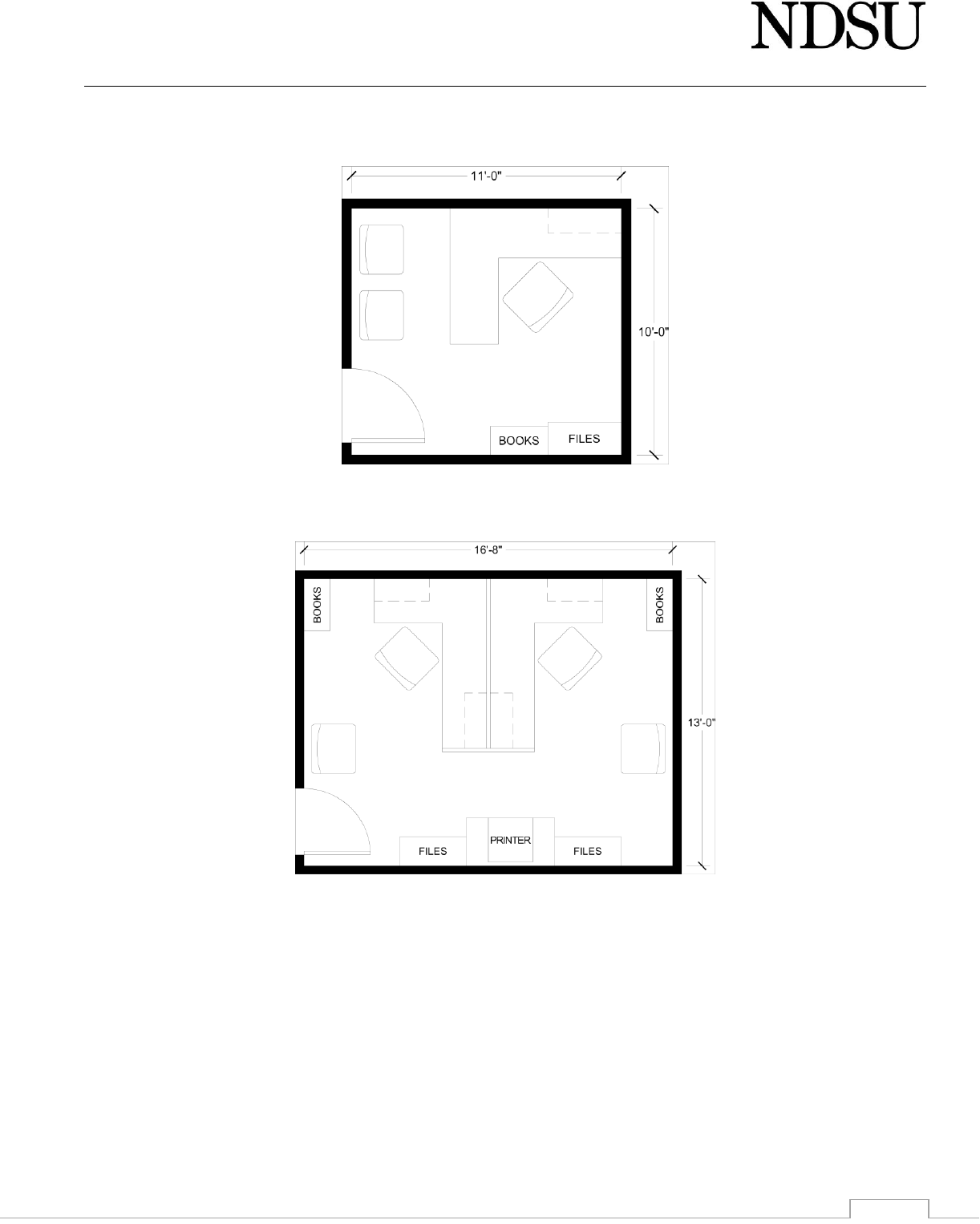
3) Office layout examples
A) Below are some examples of diagrammatic office layouts shown to help visualize efficient space
configuration. The office sizes shown align with the University Space Allocation Guidelines and indicate
NDSU expectations.
B) While private offices for staff (administrative and research) and graduate students are generally preferred
over modular workstations, open office systems are being increasingly utilized both in the corporate sector
and on campus. Implementing a modular planning approach can provide countless layout options while
preserving the flexibility of a space for changes in future programmatic requirements.
C) It is understood that existing buildings (especially older buildings) do not always offer uniform sized spaces
and may prevent precise conformity to the Space Allocation Guidelines. Nonetheless, these layouts present
a sampling of commonly used arrangements for reference in planning the use of your spaces and can be
adapted to various sized rooms.
D) Associate Dean, Director, Chair office – 180 square feet.
Design Guidelines Facilities Management
01-2
1) Unit head’s office is an individual, private office able to contain a desk, file cabinet(s), book shelves and
a meeting area for up to four people.
E) Full-time Faculty / Staff / Emeritus Faculty office – 110 square feet.
1) Full-time, professional and administrative staff and emeritus faculty office that will accommodate a
desk, file cabinet, bookshelf and an area capable of holding meetings.
F) Shared Staff office – 120 square feet per person
1) Shared offices can provide a viable option when space is limited or when staff work on similar tasks.
When personnel do not require a private office work when they work with sensitive documents, a
shared office may prove more secure than an open-office layout.

Design Guidelines Facilities Management
01-3
G) Post Doc – 100 square feet
1) Post doctorate fellows, research assistant or technician requiring the privacy and security of an
individual office.
H) Scholars / Fellows / Grad associate – 40 square feet per person
1) Visiting scholars, Fellows and Trainee offices are assigned shared office space occupied by two or more
persons depending on the type of appointment (full or part-time), program needs and existing building
conditions. The figure above shows one possible layout for associates sharing a single office. Modular
work stations at 7’x6’ each are also an excellent option.
4) Lactation Room example
5) Guidelines for Creating and Remodeling Learning Spaces can be found at:
https://www.ndsu.edu/fileadmin/provost/LSEC/NDSU_Classroom_Design_Manual.pdf

Design Guidelines Facilities Management
01-4
01 14 00 Work Restrictions (Site Access, Occupant Coordination, Site Use)
1) Tobacco is not permitted on Campus grounds or in buildings and structures. Anyone caught using tobacco
products on campus will be removed from the jobsite.
2) Consuming prepared foods is allowed on the construction site and within the building. If this privilege is abused,
food will no longer be allowed within the building and must be consumed in a job trailer or outside the building.
3) Radios, tape players, compact disc players, etc. will not be allowed.
4) Owner reserves the right to halt all work on the construction site if the work is interfering with nearby facilities
until that interference is corrected. Owner will provide the contractor with adequate information so this
condition could be avoided; however, University activities may not be interrupted.
5) Contractor shall provide a minimum of 48 hour notice of utility or service shutdowns.
6) Unmanned Aircraft Systems (UAS) or drone flights shall follow the procedures located at the following address:
A) https://www.ndsu.edu/research/for_researchers/unmanned_aircraft_systems/
01 20 00 Change Order Procedures
1) A Change Order is a written instrument prepared by the Architect and signed by the Owner, Contractor and
Architect stating their agreement upon all of the following:
A) The change in the Work;
B) The amount of the adjustment, if any, in the Contract Sum; and
C) The extent of the adjustment, if any, in the Contract Time.
2) When either or both additions and credits covering related work or substitutions are involved in any one change,
the allowance for overhead and profit shall be calculated on basis of the net amount of cost or credit.
A) The allowance for overhead, bond, and profit combined, included in the total cost shall be based on the
following schedule:
1) For the Contractor; for added or deleted work performed by the Contractor’s own forces, 10 percent
of the cost.
2) For the Contractor; for added or deleted work performed by the Contractor’s Subcontractor, 5
percent of the cost due the Subcontractor.
3) For each Subcontractor or Sub-subcontractor involved; for added or deleted work performed by the
Subcontractor’s own forces; 10 percent of the cost.
4) For each Subcontractor; for added or deleted work performed by the Subcontractor’s Sub-
subcontractor, 5 percent of the amount due the subcontractor.
B) In order to facilitate the checking of quotations for extras or credit, all proposals, except those so minor
that their propriety can be seen by inspection, shall be accomplished by a complete itemization of costs
including labor, materials, and subcontracts. Labor and materials shall be itemized in the manner described
above. Where major cost items are subcontract, they shall be itemized also.
C) In no case will a change involving over $100.00 be approved without such itemization.
01 31 00 Coordination
1) Contractor shall coordinate an above ceiling inspection of all rooms by providing a 48 hour notice before ceiling
tiles are installed for owner’s personnel to view above ceiling areas for locations of valves, VAV boxes, etc.
2) Communication is of the utmost importance and the proper lines of communication often avoid unnecessary
delays and misunderstandings.
3) Progress Meetings:
A) Required Attendance:
1) Architect and their professional consultants, as needed.
2) Prime Contractor’s project manager and field superintendents/foremen. Subcontractors and suppliers
as appropriate to the agenda.
3) All Prime Contractors shall have any subcontractor(s), who are within a 2 week window of starting
work, present at the progress meetings for the purpose of coordination of their work with all others
working on the site.
4) Onsite Coordination Meetings:
A) The General Contractor’s Superintendent shall conduct a brief daily coordination meeting with site
superintendents/foremen of the other Primes, and all subcontractor foremen that are working on site, for

Design Guidelines Facilities Management
01-5
the purposes of onsite communication, coordination and dissemination of information.
5) Schedule Coordination
A) The overall construction schedule is managed by the General Contractor. All Prime Contractors are
responsible for coordinating their work through the General Contractor and cooperating with all trades to
ensure the work progress of others is not impeded.
01 33 00 Submittals
1) Provide the Owner with one copy of Shop Drawings for review when forwarded to Consultant from Contractor.
The Owner will review each submittal and reply to appropriate Consultant if modifications need to be made.
2) Shop drawings for review and “For Construction” will be submitted to the Owner in digital format, with hard
copies provided in the Operation & Maintenance Manuals only.
3) Schedules:
A) The overall construction schedule, approved and signed by all of the Prime Contractors, must be submitted
within three (3) weeks of the date of the Contract.
B) The first schedule signed off by all of the Prime Contractors, and approved by the Architect and Owner will
be the schedule for the project. Subsequent schedules will show variances to the schedule, accurately
indicating tasks that are behind, ahead or on schedule. The schedules will be created in a scheduling
program such as Microsoft Project, SureTrack/Primavera or Expedition that is capable of showing the
progress and any variations accurately. Electronic copies will be made available to the Architect and/or
Owner upon request.
C) Schedules will be updated by the General Contractor, with the coordination, cooperation and input by the
other Prime Contractors. The other Prime Contractors shall supply tasks, accurate dates and timeframes for
purpose of completing the schedule expeditiously and accurately. Copies of this updated schedule will bear
the signatures of all Prime Contractors acknowledging their acceptance. Signed copies shall be provided to
the Architect and Owner one (1) week prior to submission of all Applications for Payment.
D) If a Prime Contractor falls behind on the schedule due their lack of manpower, equipment, coordination
with other Prime Contractors, or their own negligence, the Owner will direct the Prime Contractor to use
whatever means necessary to get back on schedule. This may include, but is not limited to, working
overtime, increasing manpower, or bringing in additional forces all at the expense of the Prime Contractor.
If so directed, the Contractor shall abide by the direction of the Owner or risk being in breach of contract,
allowing the Owner to hire additional forces to recover the lost time and deducting the cost from the Prime
Contractor’s contract.
01 35 00 Special Project Procedures
1) Storm Water Pollution Prevention Plan
A) Storm water permitting shall follow NDDH guidelines and the following procedure:
1) The Consultant shall on behalf of the Owner provide the Contractor with a preliminary Notice of
Intent (NOI), Storm Water Pollution Prevention Plan (SWPPP), and Acceptance of Ownership form
upon award of the project contract.
2) The Contractor shall review, amend, complete, and sign all required components of the NOI, SWPPP
and Acceptance of Ownership form. Additional sediment and erosion control Best Management
Practices (BMP’s) and other features including a proposed timetable of sediment and erosion control
activities shall be added to the SWPPP by the contractor:
http://www.ndhealth.gov/WQ/Storm/Construction/ConstructionHome.htm
3) The contractor shall return the completed NOI, SWPPP, and Acceptance of Ownership form to the
Consultant and allow for a minimum of two (2) days for review and approval of the NOI and SWPPP
by the Owner or its designated representative prior to signature of the NOI by the Owner. The Owner
does not sign the SWPPP.
4) The NOI shall be submitted by the Consultant on behalf of the Owner to the NDDH 7 days prior to
commencement of construction. The contractor shall not begin Construction activities prior to the
seventh (7th) day after submittal of the NOI to the NDDH or until acknowledged in writing by the
NDDH, whichever is sooner.
5) If the project involves 50 or more acres, or if the project has a discharge point located within 2,000
feet of, and flows to, a water body listed as impaired under section 303(d) of the Federal CWA due

Design Guidelines Facilities Management
01-6
to sediment or parameters associated with sediment transport, the SWPPP shall be submitted with
the Notice of Intent to the NDDH. A list of North Dakota’s water quality-limited waters needing total
maximum daily loads or TMDLs developed to comply with section 303d of the Federal CWA can be
found at: http://www.ndhealth.gov
B) By signing the Contract and completing the NOI, the Contractor is a co-permittee with the Owner to ensure
compliance with the terms and conditions of the General Storm Water Permit and is responsible for
complying with all provisions of the permit. The contractor is solely responsible for the execution of the
SWPPP according to Part II C of the General Storm Water Permit
C) Fire walls, fire barriers, fire partitions, smoke barriers and smoke partitions or any other wall required to
have protected openings or penetrations shall be effectively and permanently identified with signs or
stenciling. Such identification shall:
1) Be located in accessible concealed floor, floor-ceiling or attic spaces
2) Be located within 15 feet (4572 mm) of the end of each wall and at intervals not exceeding 30 feet
(9144 mm) measured horizontally along the wall or partition
3) Include lettering not less than 3 inches (76 mm) in height with a minimum 3/8 inch (9.5 mm) stroke
in a contrasting color incorporating the suggested wording. "FIRE AND/OR SMOKE BARRIER—
PROTECT ALL OPENINGS" or other wording.
4) Exception: Walls in Group R-2 occupancies that do not have a removable decorative ceiling allowing
access to the concealed space.
01 51 00 Temporary Utilities
1) Temporary utility services for the construction site will be installed by the appropriate contractor and must be
coordinated with the Owner prior to connections being made.
2) Electrical Power Service:
A) Temporary power shall be installed following NEC Article 590.
B) Power will be available to the site from a near-by transformer or building and will be metered with a
Contractor-provided meter.
C) NDSU will read the meter and bill the General Contractor accordingly; Xcel Energy will not meter nor read
the meter at the site.
D) Depending on the job size, power may be supplied without cost at the discretion of the Owner.
3) Water Service:
A) Water will be available to the site from a near-by University water distribution source with a backflow
prevention device and will be metered with a Contractor-provided meter.
B) NDSU will read the meter and bill the General Contractor accordingly; City of Fargo will not meter nor read
the meter at the site.
C) Depending on the job size, water may be supplied without cost at the discretion of the Owner.
4) Heat and Steam Service:
A) All Work that requires heat in new construction will be the responsibility of the Contractor.
B) Through an agreement with the Owner, the Contractor may buy steam from the main Campus steam
distribution system.
C) Usage of the steam will be billed back to the Contractor based on a value per thousand pounds of steam
condensate measured through an Owner supplied condensate meter.
5) Telephone, Internet and Fax Service:
A) Telephone, Internet and fax services may be provided through the NDSU Telecommunications department
and billed to each Prime Contractor that requires a connection.
B) Cellular phone service will be the responsibility of the Contractor.
6) Abuse of the Owner-provided temporary services will result in the Owner billing the contractor for those utilities
being abused.
A) Prior notification will be provided to the Contractor of abuse to cease the abuse.
B) The Owner will make the final decision on who the abuser was and the amount of wasted services.
01 52 00 Construction Facilities
1) Sanitary Facilities:
A) Contractors may be allowed to use the facilities for Work that will take place in a building with existing,

Design Guidelines Facilities Management
01-7
operating sanitary facilities.
B) Care must be made to keep these facilities in a clean and sanitary condition.
C) The General Contractor will be responsible to supply portable toilet facilities at the site for new
construction. Nearby buildings will not be allowed unless the General Contractor has received permission
from the Owner.
2) Site Storage:
A) All material and equipment shall be confined to the area allowed by Owner unless prior approval was
granted to store material outside the area of work.
B) Excess black dirt may be reused on the NDSU campus at Owners discretion.
C) Excess clay or contaminated material will be removed from campus and become the property of the
Contractor.
01 55 00 Vehicular Access and Parking
1) Traffic routes will be as directed by the Owner.
2) ON-CALL SERVICES:
A) Any contractors/vendors performing on-call (non-scheduled) services to NDSU buildings or property may
do so WITHOUT purchasing any type Parking Permit from NDSU, but their vehicle(s) shall meet the following
criteria to be eligible for parking on NDSU property.
1) Vehicles shall be easily recognizable as a commercial service vehicle.
2) Vehicles shall be painted on the exterior with a 'branded logo' or have an appropriately sized
magnetic or attached sign.
3) Vehicles shall be parked in legal and/or authorized parking areas or they will be subject to parking
citations.
3) LONG-TERM SERVICES:
A) Any contractors/vendors performing on designated long-term NDSU projects shall also be allowed to park
on NDSU property if their vehicle(s) meet the same criteria as stated above.
B) Contractors/vendors shall be instructed of the work site parking conditions at the pre-performance
conference and shall confer with their assigned NDSU Project Manager as to where they shall park their
company vehicles while working on NDSU property.
4) UNMARKED CONTRACT/VENDOR VEHICLES
A) Shall NOT be allowed to park on NDSU property without purchasing an NDSU parking permit. Failure to
purchase a parking permit while parked on NDSU property will result in a parking citation.
5) NDSU PARKING PERMIT PURCHASE OPTIONS
A) One-Year Parking Permit for Contractors/Venders = $185.00 per year
B) One-Day Parking Permits for Contractors/Venders = $2.00 per day
C) Temporary Parking Permits for Contractors/Venders = $2.00 per day (Maximum of 6-weeks)
D) Summer Parking Permits for Contractors/Venders = $25.00 summer only (May 15 to August 15
approximately)
E) Metered parking at any of the four pay lots on the NDSU campus.
6) NOTES:
A) Contractors'/vendors' shall determine which permit or combination of permits works best for their
situation.
B) There are no refunds for parking permit purchase fees. All sales are final.
C) All citations received are the responsibility of the vehicles registered owner.
D) CONSULT YOUR NDSU PROJECT MANAGER ABOUT BUYING PARKING PERMITS AND METERED LOTS.
01 56 00 Temporary Barriers and Enclosures
1) The Contractor shall confine apparatus, material storage, and the operation of the workers to limits indicated
by the construction site boundaries.
A) These boundaries are to be fenced-off by use of a chain link fence at minimum height of six feet and
maintained in good condition through the completion of the project.
B) If this confinement is not possible, prior approval must be obtained from the Owner, via the project
Consultant, before other University space is utilized by Contractor.
C) As per state law and city ordinance regarding trespassing, the name of the person posting the premises

Design Guidelines Facilities Management
01-8
must appear on each sign in legible characters.
D) The signs shall read:
No Trespassing
Violators will be Prosecuted
(Contractors name)
(Contact Name) – could be a foreman, supervisor, project manager, presidents name
E) Place at all entry gates, areas of egress, and every 40-50 feet along fence.
2) Site Traffic:
A) Contractor may not block traffic or pedestrian use other than designated work area.
B) Contractor shall supply and maintain all barricades to block-off the work area.
01 56 39 Temporary Tree and Plant Protection
1) Protect all existing trees and other planting areas that will not be directly affected by the work. Existing trees
and other planting areas which are damaged due to work shall be repaired or replaced to original condition.
A) Fence shall be installed 3’-0” beyond the drip line of trees and plantings.
B) No equipment or materials shall be placed within the protected fencing.
C) No chemicals, dirt, or construction debris shall be placed within the protected fencing.
D) There shall not be cutting or breaking of branches without notifying the Owner’s Landscape/Arboretum
Coordinator.
E) No damage shall be done to the tree trunks; this includes bark removal, cutting into the trunk, equipment
leaning against the trees, etc.
F) When excavation operations are in proximity to trees, the root system shall be cut by hand at the limits of
the excavation prior to any soil removal.
01 57 00 Temporary Controls
1) Erosion and sediment control is required on all construction projects; contractor shall comply with the local
authority having jurisdiction and NDPES requirements and procure the appropriate permits.
01 60 00 Product Requirements
1) This paragraph must be included in the specifications for every project:
A) Proprietary Specification Requirements: There are no proprietary specifications in this project. No product
will be sole sourced. Substitutions are allowed for all products, as long as the procedures indicated within
these specifications are adhered to. Substitutions must be approved by the architect prior to acceptance.
2) The products and materials listed in this Guideline are those that NDSU has utilized and currently requires.
A) Any product or material that may be substituted requires prior approval by the Owner.
B) Within the specifications, require seven working days prior to the date of receipt of bids for review of
substitutions by the Owner and the Consultant.
C) No substitutions will be considered after the project has begun unless provided within the Contract.
3) No products or building materials used as a temporary or permanent element in the construction of a building
will be allowed which have any form of asbestos containing or lead containing material.
A) Contractors shall be responsible to monitor shop drawings and product literature to verify the make-up of
materials to be used in the building, and to remind material suppliers that their products must not contain
asbestos or lead.
B) Contractors shall notify the Architect immediately of any materials which are suspected of containing
asbestos, and shall not disturb or attempt to abate any asbestos containing material. The Architect will
contact the Owner and inform the Owner of the Contractors observations. The Owner will obtain and
provide the services of professionals skilled in asbestos or lead removal.
C) At the completion of construction, during the close-out phase of the project, Contractor shall complete the
Contractor Certificate of Non-Asbestos and Non-Lead Materials (See 01 78 00.10.A) (Exhibit O).
4) Use poured concrete foundations, avoiding block wall foundations on exterior walls.
5) Architectural surfaces:
A) All surfaces should be hard surfaced, such as, brick, stone, structural concrete, marble, etc.

Design Guidelines Facilities Management
01-9
B) Exclude plastic or other types of surfacing materials which might require replacing or refinishing in future
years.
C) No exterior surfaces should require painting.
D) Other exterior metals should be corrosion free and non-ferrous, for example, stainless steel and/or
anodized aluminum.
E) Baked enamel steel is acceptable for roof and downspout applications.
01 73 00 Execution
1) The Consultant is responsible for maintaining accurate AS-BUILT drawings and specs showing any changes to
the contract documents.
01 74 00 Cleaning and Waste Management
1) All construction debris shall be removed from the site on a daily basis.
2) Cleaning:
A) All Contractors will keep the premises free from waste material accumulation, or rubbish created by the
construction project. Cleanup shall be conducted every day, with a thorough cleaning by all contractors by
end of the work week.
B) If the project is an interior renovation in an occupied building, the building shall be thoroughly cleaned daily.
Consult with the Owner on cleaning requirements.
C) If the Owner should determine the Contractor to be negligent in this respect, the owner reserves the right
to use his own resources for such cleanup. The cost will be charged back against the Contractor.
3) Contractor shall be responsible for performance of any lawn care and weed control measures within the
designated construction site to prevent the passive cultivation and seeding of unwanted plants.
01 77 00 Closeout Procedures
1) Upon completion of the project and before final payment is made, the Consultant shall complete the
requirements of sections 01 77 00 through 01 78 44.
A) All documents required in these sections shall be delivered to Owner.
2) Mechanical close-out requirements
A) Final inspection by the Owner will not be conducted prior to delivery of all air balance and performance
data, plus a spare parts list, operating instructions, and equipment descriptive literature that contains
complete numbered replacement parts list.
B) Test data information will be obtained by an independent firm. The firm shall be responsible to Owner.
C) Air flow, temperature, ampere readings, etc., shall be recorded and become the property of the Owner.
3) Warranty inspection:
A) The respective consultants shall set up a final warranty inspection on the eleventh month after substantial
completion (referred to as “One Year Warranty Inspection”).
B) The Architect shall arrange for an inspection of the mechanical systems 10 months after date of final
acceptance for the purpose of work that should be corrected under the one year guarantee provisions of
the contract.
01 78 00 Closeout Submittals
1) Exhibit C of these Guidelines contains the check-off sheet for the items in this section.
2) One copy of field noted, construction drawings (“Red Line Drawings”) shall be delivered to Owner.
3) Record Drawings:
A) Two (2) complete printed sets of Record Drawings:
1) May not be sized larger than 30”H x 42”W (ARCH E1)
2) Drawings must be updated to reflect all change orders, field changes, and revisions. Handwritten
notations and field notations are not acceptable.
B) One (1) set of electronic Record Drawings:
1) Must be in AutoCAD “.dwg” format.
2) Final electronic Record Drawings must reflect all field changes & revisions.
4) One (1) updated hardcopy of the specifications with addendum(s) incorporated into the specifications and a
copy of the updated specifications in PDF (or .doc/docx) format.

Design Guidelines Facilities Management
01-10
5) A painting schedule noting all paints and stains used on the project. Designate this information by using the
room number.
6) A valve chart for all valves will be provided with valve enumeration, location, and type identified (i.e. Main Shut-
Off, Return Valve, etc.).
7) A complete set of shop drawings.
8) The sign-in sheet listing all owner's employees at the training function provided as part of “Equipment Operating
Instruction” (required in 01 79 00.1.B).
9) HVAC system testing and balancing reports (required in 01 77 00.2).
10) The following completed documents:
A) A Contractor Certificate of Non-Asbestos and Non-Lead Materials (Exhibit O).
B) AIA G704-2000 Certificate of Substantial Completion; or,
1) AIA G704CMa-1992 Certificate of Substantial Completion, Construction Manager-Advisor Edition
may be substituted if applicable; or,
2) AIA G704DB-2004 Certificate of Substantial Completion of a Design-Build Project may be substituted
if applicable
C) AIA G705-2001 List of Subcontractors
D) AIA G706-1994 Contractor’s Affidavit of Payment of Debts and Claims, including AIA G706A-1994
Contractor’s Affidavit of Release of Liens
E) AIA G707-1994 Consent of Surety to Final Payment
F) Certificate of Occupancy issued by the local authority
01 78 23 Operation and Maintenance Data
1) Operating and Maintenance Manuals:
A) Two (2) hardcopy of instructional operating and maintenance manuals and product information on all
equipment and finish materials.
1) Items shall be indexed according to the Construction Specification Institutes indexing system and
separated by a tab system (ie: 05 50 00 Metal Fabrications).
B) One (1) electronic copy in PDF format of instructional operating and maintenance manuals and product
information on all equipment and finish materials.
C) Include part books on every piece of equipment that operates or has moving or electrical parts, for example:
elevators, door hardware, alarm systems, etc.
D) Warranties:
1) Include all warranty information, cut sheets, and owner’s manual which is to include the operating
procedures, product maintenance schedule, and maintenance requirements.
01 78 36 Warranties
1) Warranty items will be repaired within one (1) week. If not repaired, Owner will have the item in question
repaired and will invoice the responsible party.
2) Roofing Contracts:
A) A contractor’s “Five Year Roof Guarantee” (Exhibit D) shall be completed by the contractor for all roof
projects and submitted to Owner.
B) Manufacturer’s membrane roofing warranties shall be a minimum of twenty (20) years.
C) Sheet metal roofing warranties shall be a minimum of 20 years.
3) Casework shall be provided with a five (5) year guarantee against defective material and fabrication.
4) Warranties are to be included with Operation and Maintenance Data submittals, see also 01 78 23.D
5) NDSU will charge back to the contractors and/or suppliers time spent by Owner staff investigating and
diagnosing items that turn out to be warranty claims.
6) For warranty items that require immediate response in which the NDSU knows which warranty the item is for,
NDSU will call the 24-hour call number provided by contractors. If NDSU cannot get a hold of anyone within
ten minutes, NDSU will take any necessary actions to temporarily or fully correct the issue depending on the
fault and will fully and accurately bill all time and material including any overtime costs to the prime
contractor responsible either for the prime’s work or the sub-contractor of the prime. This also includes any
consequential damages that arise due to the warranty issue.

Design Guidelines Facilities Management
01-11
7) For warranty items that do not need immediate response, NDSU will contact the prime contractor to schedule
any necessary repairs.
01 78 44 Extra Stock Materials
1) A complete replacement set of HVAC air filters and belts provided per 23 40 00 must be supplied at the
completion of the project.
2) Extra quantities of the following products shall be made available to the Owner for future use to replace
damaged materials (see also 09 05 00)
A) Ceiling Tile – Minimum of 3 boxes, up to 5% needed for project with a maximum of 10 boxes
B) Ceramic Tile – Minimum of 2 boxes, up to 5% needed for project with a maximum of 5 boxes of each color
C) Carpet Tile – Minimum of 3 boxes, up to 5% needed for project with a maximum of 10 boxes
D) Other Flooring – Minimum of 2 boxes, up to 5% needed for project with a maximum of 5 boxes
E) Paint – 1 gallon of each color, unopened and labeled “For NDSU Use Only”
F) Terrazzo Flooring – Five gallon bucket of extra stone
G) Epoxy Flooring – Five gallon bucket of extra flakes
H) Polished Concrete – Five gallon bucket of extra aggregate
01 79 00 Demonstration and Training
1) Equipment operating instructions:
A) All consultants shall set up training sessions for their respective products. Contact the Owner’s
representative to schedule the meeting times.
B) A sign-in sheet shall list all Owner's employees at the training function.
01 80 00 Performance Requirements
1) Architect to perform an eleven (11) month inspection of project and arrange with contractor to remedy any
outstanding issues.
01 81 00 Facility Performance Requirements (Alternate)
1) The University fully supports the principles of the LEED (Leadership in Energy and Environmental Design) Building
Rating System. All projects shall address sustainability as it relates to site issues, water, energy efficiency,
materials and resources and indoor air quality.
A) The Consultant shall strive to meet or exceed the minimum number of points needed for LEED certification
under the rating system appropriate for the project.
B) The Consultant shall determine the most cost effective means of achieving these points, and shall take full
credit for points achieved through compliance with other University standards that address sustainability
issues, such as building commissioning.
C) The Consultant shall submit for the University’s review and approval a LEED Project Checklist, identifying
the specific measures proposed to be incorporated into the project to achieve the target number of points.
D) If the point level for LEED certification may not be affordable within the authorized budget for a given
project due to the cost of achieving the total number of LEED points needed for certification, then as many
features as can be afforded shall be maintained in the design. This will be addressed on case-by-case basis.

Design Guidelines Facilities Management
02-1
Site Construction
02 30 00 Subsurface Investigation
1) The contractor is responsible for the payment of all retesting services of any tests which fail to meet project
specifications.
02 40 00 Demolition and Structure Moving
1) Concrete and Asphalt Removal
A) Where practical, all concrete and asphalt shall be recycled.
B) All concrete and asphalt surfaces are to be saw cut to the surfaces full depth from the area that is to be
kept. Asphalt pavement may be cut with a coultier with the approval of the Owner.
C) All roots or other vegetation more than one inch in thickness below the finished surface shall be removed
to a depth of six inches below the base of the surface.
2) Underground Utility Demolition
A) All unused or abandoned piping within the limits of the construction site shall be removed and salvaged
by the Contractor. Verify pipe insulation and jackets for asbestos containing material before removal.
B) All unused or abandoned electrical wiring and conduit within the limits of the construction site shall be
removed and salvaged by the Contractor.

Design Guidelines Facilities Management
03-1
Concrete
03 05 00 Common Work Results for Concrete
1) Concrete Advertising Stamp: Stamps advertising ones company are not acceptable anywhere on campus.
03 10 00 Concrete Forming
1) Forms shall be set upon the compacted sub-grade to the exact grade and alignment.
2) Sidewalk side to side slope is not to exceed 2%, unless otherwise directed by Owner.
3) The slope of walkways and ramps must exceed ADA requirements by 0.5%. The contractor is expected to use any
means and methods to ensure there are no points that are greater than slopes allowed by ADA.
4) Deposit concrete in excess of the required depth, compacted or vibrated with as little handling to fill all voids, and
finished smooth and even.
5) Broom the surface transversely across the pavement sufficiently to leave marks, not grooves.
03 15 00 Concrete Accessories
1) Install elasticized sealant in joints with expansion material 48 hours after concrete pour. Clean joints prior to placing
sealant.
2) All truncated domes shall be non-painted cast iron.
A) Radius sidewalks shall use radius truncated domes.
03 20 00 Concrete Reinforcing
1) Place steel on plastic chairs only.
2) Reinforcement in bike pads, sidewalks and other walking surfaces and garbage dumpster pads shall be #4 rebar
placed at 18” O.C.
03 30 00 Cast-In-Place Concrete
1) Materials:
A) Portland Cement: Type I - ASTM C150; Type III - High Early Strength C150
B) Aggregates:
Fine Aggregates
Sieve Designation
Weight Passing
Square Mesh Sieve
Course Aggregate:
3/8"
100%
Shall conform to size No. 57, one
inch to No. 4.
No. 4
95 – 100%
No. 8
80 – 100%
No. 16
50 – 85%
No. 30
25 – 60%
No. 50
10 – 30%
No. 100
2 – 10%
C) Reinforcing Steel: New steel conforming to ASTM A615, Grade 60, deformed bars
D) Dowel bars conforming to ASTM A615, Grade 40, non-deformed, plain bars
E) Joint Expansion Filler: Resin impregnated fiberboard, minimum thickness 1/2 inch .
F) Joint Sealer: Hot poured elastic type
G) Curing Compound: White acrylic based curing and sealing compound with 18 percent minimum solids content.
2) Proportions:
A) 28-day strength to meet the surface specified psi.
1) If 28-day strength is not met, concrete shall be replaced at contractor’s expense.
B) Water cement ratio not to exceed 0.45.
C) Air content of air-entrained concrete shall not be less than five percent, nor more than eight percent (8%) of
volume.
D) Fly-ash maximum percentage will be 30.

Design Guidelines Facilities Management
03-2
E) Slump shall not exceed four inches; when using slip forming equipment, slump shall not exceed 1 1/2 inches.
3) Properties:
Concrete type
Thickness
Strength
Bike pads
6”
4500 psi
Sidewalks
6”
4500 psi
Dumpster pads
6”
4500 psi
Streets/ Dumpster Approaches
8”
5000 psi
A) Sidewalks to be a minimum of seven (7) feet wide. When two sidewalks join, provide a radius equal to half the
sum of the sidewalk widths.
03 35 00 Concrete Finishing
1) Use any means and methods necessary to saw joints in the concrete paving to prevent uncontrolled cracking.
2) Tool expansion joints into the wet concrete or “green sawed” within 12 hours after the concrete placement.
A) Placement of joints to be coordinated with Owner.
B) Provide broom finish for sidewalks.
3) Within the first year of installation, remove and replace concrete pavement where uncontrolled cracks have
occurred at no cost to the Owner.
4) Within the first two years of installation, any surface rock pops/blowouts shall be repaired with an epoxy or grout
material.
03 35 11 Concrete Floor Finishes
1) Reference Standards
A) ASTM C779 – Standard Test Method for Abrasion Resistance of Horizontal Concrete Surfaces.
B) ASTM F609 – Standard Test Method for Using Horizontal Pull Slip Meters (HPS).
C) ASTM E1155 – Standard Test Method for Determining F(F) Floor Flatness and F(L) Floor Levelness Numbers;
1996 (Reapproved 2008).
2) Delivery, Storage and Handling
A) Deliver Materials in manufacturer’s sealed packaging, including application instructions.
B) Container Label: Include Manufacturer’s name, type of paint, brand name, lot number, brand code, coverage,
surface preparation, drying time, cleanup requirements, color designation and instructions for mixing and
reducing.
C) Store materials in a clean, dry area in accordance with manufacturer’s instructions.
D) Keep materials from freezing.
E) Avoid direct contact with this product as it may cause mild to moderate irritation of the eyes and/or skin.
F) Protect materials during handling and application to prevent damage or contamination.
3) Manufacturer
A) Prosoco or approved equal.
4) Concrete Floor Finish Applications
A) Liquid Densifier/Hardener
1) Use at the following locations: At all interior locations throughout project where concrete floor is to be
exposed.
2) Consolideck by Prosoco, PL Premium Lithium-Silicate Sealer, Hardener & Densifier for Concrete or
approved equal.
B) Penetrating Translucent Color Dye (Stain)
1) Consolideck by Prosoco, GemTone Stain, Penetrating Translucent Color Dye for Concrete or approved
equal.
2) Selected Colors, or owner approved equal:
a) Amber
b) Light Roast
c) Desert Sand
C) High Gloss Clear Sealer

Design Guidelines Facilities Management
03-3
1) Use at the following locations: Where sealed concrete, stained concrete and polished concrete floor
finishes are indicated.
2) Consolideck by Prosoco, LS Guard, Glossy Sealer, Hardener & Densifier for Concrete or approved equal.
5) Accessories
A) Consolideck surface preparation cleaner or mechanical process to remove surface contaminants.
6) Examination
A) Verify that floor surfaces are acceptable to receive the work of this section.
B) Verify that flaws in concrete have been patched and joints filled with methods and materials suitable for further
finishes.
C) Notify Architect if surfaces are not acceptable. Do not begin application until unacceptable condition(s) have
been corrected.
7) Surface Preparation
A) Protect adjacent surfaces not designated to receive treatment. Use polyethylene or other proven protective
material.
B) Clean and prepare surfaces to receive treatment in accordance with manufacturer’s instructions ensuring that
all stains, oil, grease, form release agents, dust and dirt are removed prior to application.
C) Do not apply to surfaces which are frozen, dirty or have standing water. Surface must be clean, dry and
absorbent. Confirm surface with a light water spray – surfaces designated for treatment should wet uniformly.
If surface does not wet uniformly, use the appropriate surface preparation cleaner or mechanical process to
remove remaining surface contaminants.
8) Surface and Air Temperatures
A) Verify that surface and air temperatures are as recommended by manufacturer.
1) Temperatures for application should be between 40-100 degrees F.
2) Do no begin product installation until required surface and air temperature conditions are met.
9) Densifiers and Hardeners Application
A) Test Application: Test a small area of each surface to confirm suitability and desired results before starting
overall application. Test with the same equipment, recommended surface preparation and application
procedures planned for general application.
B) Clean concrete of any dirt, residue or soft cut saw debris.
C) Ensure application equipment is clean and free of previously used materials.
D) Do not dilute densifier and chemical hardener.
E) Apply materials in accordance with manufacturer’s instructions.
1) Using low pressure sprayer fitted with a 0.5 gpm spray tip, apply a single coat of LS. Apply sufficient
material to wet the surface without producing puddles. Use a clean soft-bristle push broom or microfiber
pad to spread product evenly and ensure uniform wetting. Avoid spreading once drying begins. Scrubbing
is not necessary. If surface dries immediately, apply more product. Surface should remain wet for 5-10
minutes. Adjust rate of application to eliminate puddles.
2) Allow treated surfaces to dry.
3) Immediately apply the specified curing compound or initiate the specified curing procedure.
4) When curing process is complete, use an automatic floor scrubber equipped with cleaning pads or
brushes appropriate for removal of construction soiling and surface residues. Avoid pads or brushes
which may damage the finished floor. This procedure will further enhance the surface sheen produced
by Consolideck LS.
10) Penetrating Translucent Color Dye (Stain) Application
A) Verify that surface temperatures are as recommended by manufacturer.
1) Temperatures for application should be between 50-90 degrees F.
2) Do no begin product installation until required surface and air temperature conditions are met.
B) Ensure application equipment is clean and free of previously used materials.
C) Test Application: Test a small area of each surface to confirm suitability and desired results before starting
overall application. Test with the same equipment, recommended surface preparation and application
procedures planned for general application.
D) Dilution and Mixing: As per manufacturer’s recommendations.
E) Execute using materials, equipment and procedures specified by manufacturer, using manufacturer approved
installer. Burnish concrete densifier treated floors in accordance with the following:

Design Guidelines Facilities Management
03-4
1) Allow densifier and hardener to “cure” for a minimum of 28 days before beginning the application of
polishing and staining.
F) Application Instructions: Color (stain)
1) Diamond grind and polish the surface to the equivalent of #200 grit resin diamonds.
2) Clean the floor with a floor-scrubbing machine and fresh water. Let floor dry.
3) Lightly wet a clean microfiber pad with the prepared stain.
4) Apply the prepared stain to the clean, dry concrete floor using a low-pressure sprayer with a conical
spray pattern. Wet the surface without producing puddles. Do not over apply. Use a small bucket or rag
to collect drips when not spraying.
5) Using the wet microfiber pad, immediately spread the spray-applied stain to ensure uniform wetting and
color distribution. Continue spray-applying. Maintain a wet edge. Work the color into the surface to
minimize streaks and patterns. Provide two people – one spraying and one spreading – for best results.
6) Do not walk on the freshly stained surface. Let the floor dry thoroughly, 60 minutes minimum.
7) Remove excess stain residue with floor scrubbing machine and fresh water. Let the wet floor dry.
8) Dry-polish to the equivalent of #400 resin diamonds. Polish until all scratch patterns are gone.
9) Clean the floor with a floor scrubbing machine and fresh water. Let the wet floor dry.
10) Apply a single coat of Consolideck LS using a low-pressure sprayer. Apply sufficient material to wet the
surface without producing puddles. Use a clean, soft-bristle push broom or microfiber pad to spread
product evenly and ensure uniform wetting. Avoid spreading once drying begins. Scrubbing is not
necessary. Allow treated surfaces to dry.
11) Dry polish to a gloss finish.
12) Sealing Stained Concrete Floor Surfaces:
a) Apply one (1) coat of sealer as described below in item “H” steps 1-5.
11) High Gloss Clear Sealer Finish Coating Application
A) Ensure application equipment is clean and free of previously used materials.
B) Verify that surface is free of previous coatings, sealers, curing compounds, water repellents, laitance,
efflorescence, fats, oils, grease, wax, soluble salts, residues from cleaning agents and other impediments to
adhesion.
C) Verify that water vapor emission from concrete and relative humidity in concrete are within limits established
by coating manufacturer.
D) Protect adjacent non-coated areas from drips, overflow and overspray. Immediately remove excess material.
E) Apply with a low-pressure sprayer and a microfiber or synthetic lint free mop. Do not atomize.
F) Test Application: Test a small area of each surface to confirm suitability and desired results before starting
overall application. Test with the same equipment, recommended surface preparation and application
procedures planned for general application.
G) Dilute as per manufacturer’s recommendations.
H) Apply materials in accordance with manufacturer’s instructions.
1) Lightly wet a clean microfiber pad with LS Guard and wring out excess, leaving the pad damp.
2) Working from one control joint to another, apply a light, fine spray of LS Guard to a small section of the
floor using a clean, pumped-up sprayer fitted with a 0.5 gpm spray tip.
3) Using the damp microfiber pad and firm downward pressure, immediately spread the product to produce
a thin, even coating. Spread the product as far as possible while maintaining a wet edge. Properly applied,
the product dries quickly. Stop spreading once drying begins. Avoid overlapping.
4) Allow to dry tack free, typically 20-60 minutes.
5) Once dry, burnish produce using a high-speed burnisher fitted with a Consolideck Heat Burnishing Pad
or equivalent polishing pad suitable for use on high-gloss finishes. In addition to smoothing and polishing
the treated surface, high-speed burnishing heats the product to help the treatment fuse and bond with
the concrete for increased durability and longevity. Surface temperature immediately behind the
burnisher must achieve 90.5 degrees F.
I) Application Schedule
1) Locations indicated as Sealed Concrete
a) Apply single coat and burnish as outlined above.
2) Locations indicated as Polished Concrete
a) Apply three (3) coats for maximum gloss as outlined above, burnish between each coat.

Design Guidelines Facilities Management
03-5
i) Note: Some locations to receive color (stain) treatment. See drawings for locations
12) Protection
A) Keep surface dry for a minimum of 48 hours after application.
03 39 00 Concrete Curing
1) Compound shall completely cover the surface, and be applied continuously and uniformly with proper equipment
maintained in good condition.
2) Contractor is responsible for taking appropriate measures to regulate the rate of cure for optimum long term viability
of the concrete.

Design Guidelines Facilities Management
04-1
Masonry
04 05 00 Common Work for Masonry
1) Install caulked expansion joints in the corners of all buildings and along the face of the buildings per the masonry
institutes guidelines.
2) All glass and metal surfaces shall be protected during brick washing. Any damaged surfaces caused by brick
washing shall be replaced by the masonry/tuckpointing contractor.
3) All concrete and/or masonry cutting, grinding, drilling, coring, or tuckpointing shall have a dust collection system
or water spray of some type. In no case should the levels of dust exceed the OSHA maximum quantities allowed.

Design Guidelines Facilities Management
05-1
Metals
05 40 00 Cold Formed Metal Framing
1) All interior metal C-studs shall be 20 ga EQ (minimum), spaced 16” O.C. and fastened at both sides on bottom
and top track.
2) Install bridging in all interior walls using bridging clips per manufacturer’s recommendations.
05 50 00 Metal Fabrications
1) All metal railing members shall be stainless steel and not contain sharp edges with welds ground smooth.
2) Riser mount railing on stairs.
3) All railing members shall be round.

Design Guidelines Facilities Management
06-1
Wood, Plastics, and Composites
06 10 00 Rough Carpentry
1) Install metal nailer strips with screws such as Carlisle’s HP Fastener for wood or steel or Rawl’s #14 Deck Screw.
2) Plywood Backing:
A) 3/4" plywood backing shall be installed at 6’-6” to 7’-6” in all classrooms, labs, and offices for present and
future wall shelving, cabinets, etc.
B) 6” tall 3/4"thick plywood backing shall be installed for base cabinets with the top of the backing 2” above
the countertop (backsplash excluded). Verify placement with Owner prior to installation.
C) Confer with the Owner about providing proper backing for specialty items, such as door stops, signage,
grab bars, etc.
3) Wall construction: (See also section 05 40 00: Cold Formed Metal Framing)
06 41 00 Architectural Wood Casework
1) See also section 12 30 00: Manufactured Casework and 12 36 00: Countertops
2) QUALITY ASSURANCE
A) Manufacturers who wish to supply cabinetry must be approved prior to the bid by submitting a sample that
meets the requirements in the casework specifications (Sections 06 41 00 and 12 30 00). Consult the Owner
representative prior to specifying this section.
1) The request for prior approval and the sample casework must be submitted ten (10) calendar days
prior to the bid opening date.
2) Manufacturer shall provide products certified as meeting or exceeding ANSI-A 161.1-2000 testing
standards.
3) At Owners request, manufacturer must submit a sample of their casework which demonstrates
compliance with the minimum levels of material and detailing indicated within the specifications.
a) Product Data: Manufacturer’s catalog with specifications and construction details.
b) Shop Drawings: Indicate dimensions, description of materials and finishes, general construction,
specific modifications, component connections, anchorage methods, hardware, and installation
procedures, plus the following specific requirements.
c) Include section drawings of typical and special casework, work surfaces and accessories.
d) Indicate locations of plumbing and electrical service field connection by others.
e) Manufacturer shall submit a base cabinet sample which conforms to specifications, with drawer
and door.
f) Manufacturer shall submit a wall cabinet sample which conforms to specifications, with door.
g) Cabinet samples shall be complete with specified hardware for doors, drawers and shelves.
h) Two sets of samples for each of the following components:
i) Decorative laminate color charts.
ii) PVC edges.
3) MATERIALS
A) Acceptable Core Materials based on thickness and application:
1) Plywood 3/4 inch thick.
B) Glass:
1) 1/4” thick laminated or tempered safety glass shall be used when cabinetry has glass sliding doors,
glass insert doors, or sliding doors mounted in an aluminum track.
2) Minimum 1/8” thick tempered safety glass shall be used for swinging doors.
C) Cabinet Hardware
1) Hinges:
a) Concealed Blum, Grass, Salice, or approved equal hinges only with soft close.
i) Doors 48 inches and over in height have three (3) hinges per door.
2) Pulls:
a) Door and drawer front pulls, are epoxy powder coated metal wire style, stainless steel or
aluminum; 96mm spacing on screws.
b) Stainless steel pulls shall be used in lab settings.
3) Drawer Slides:

Design Guidelines Facilities Management
06-2
a) All slides to be full extension with ball bearings Accuride, KV or approved equal.
b) Regular, knee space and pencil:
i) 100-pound load rated.
c) Paper storage:
i) 150-pound load rated.
d) File:
i) 150-pound load rated.
4) Adjustable Shelf Supports:
a) Each shelf support has 4 integral support pins, 5mm diameter, to interface pre-drilled holes, and
to prevent accidental rotation of support.
b) The support automatically adapts to 3/4 inch or 1 inch thick shelving and provides non-tip
feature for shelving.
c) Supports may be field fixed if desired.
5) Locks:
a) All lock hardware shall be Compx Timberline Interchangeable Lock Plug System or approved
equal.
b) Furnish 2 keys for each lock.
c) Lock for sliding 3/4 inch thick doors is a disc type plunger lock, sliding door type with strike.
d) Lock for sliding glass/acrylic doors is a ratchet type sliding showcase lock.
6) Sliding Door Track: Anodized aluminum double channel.
7) Coat Rods: 1 inch diameter, 14-gauge chrome plated steel installed in captive mounting hardware.
8) File Suspension System: Extruded molding integral with top of drawer box sides to accept standard
hanging file folders.
D) Support Members:
1) Legs:
a) Legs shall be furniture grade, epoxy powder coated steel.
b) Fixed mounted with leveling pad.
2) Under-counter support brackets:
a) Furniture grade, epoxy powder coated steel.
b) Adjustable countertop support brackets. Fixed and/or flexible rail mounted with integral wire
management and leveling pad.
E) Tote Trays:
1) Heavy-duty vacuum-formed polypropylene plastic with full top rim and pull.
2) Tote tray/supply cabinets equipped with injection molded polycarbonate; continuous side rail
support glide.
3) Each side rail support glide is adjustable with integral support pins to interface 32mm pre-drilled
holes.
F) Articulating Computer Keyboard Tray:
1) Under counter/desktop mount will be at minimum 27 inch wide flat surface with tilt, and rotation
mechanism, black molded polymer with no mouse tray slide or wrist rest.
2) Provide articulating keyboard tray only per individual request (Not all workstations will require a
keyboard tray).
4) FABRICATION
A) Fabricate casework, countertops and related products to dimensions, profiles, and details shown.
B) Chemical storage cabinets shall be metal with plastic liner and vented as required.
C) Cabinet Body Construction:
1) Cabinet Tops and Bottoms:
a) Tops and bottoms are glued and doweled to cabinet sides and internal cabinet components
such as fixed horizontals, rails and vertical. Minimum 6 dowels each joint for 24 inch deep
cabinets and a minimum of 4 dowels each joint for 12 inch deep cabinets.
b) Tops, bottoms and sides of all cabinets are plywood with plastic laminate where specified.
2) Cabinet backs:
a) Cabinet backs shall be 1/2” inch thick prefinished plywood.
b) Fixed backs:

Design Guidelines Facilities Management
06-3
i) Exposed back on fixed or movable cabinets: 3/4 inch thick plywood with the exterior surface
finished.
ii) Flexible rail mounted cabinet backs: 3/4 inch thick plywood structurally doweled into cabinet
sides and top panels.
iii) Removable backs: Provide removable backs for service access where shown on the project
drawings.
3) Fixed base and tall units have an individual factory-applied base, constructed of 3/4 inch thick
exterior grade plywood. Base is 96mm (nominal 4 inch) high unless otherwise indicated on the
drawings.
4) Base units, except sink base units:
a) Full sub-top.
5) Sink base units:
a) Provide with open top, welded steel/epoxy painted sink rail full width at top front edge
concealed behind face rail/doors, and a split back removable access panel.
b) If a soil trap is required, no bottom shelf shall be installed to allow for trap removal.
6) Side panels and vertical dividers shall receive adjustable shelf hardware at 32mm line boring centers.
7) Mount door hinges, drawer slides and pull-out shelves in the line boring for consistent alignment.
8) Edging on exposed and semi exposed edges shall be 1mm PVC.
9) Adjustable shelf:
a) In heavy-duty storage, and laboratory storage, 3/4 inch plywood laminate up to 30 inches wide
shall be used; 1 inch thick plywood laminate over 30 inches.
i) Front edge: 1mm PVC.
b) In dining service storage, use stainless steel.
10) Interior finish:
a) Top, sides, horizontal and vertical members, and adjustable shelving shall be plywood with
matching prefinished back.
b) In dining service storage, heavy-duty storage, and laboratory storage, bottom members shall be
plywood laminate.
c) In all other light-duty applications, bottom members shall be plywood with matching
prefinished back.
11) Exposed ends: Faced with VGS high-pressure decorative laminate.
12) Wall unit bottom: Faced with laminate.
13) Balanced construction of all laminated panels is mandatory. Unfinished core stock surfaces, even on
concealed surfaces (excluding edges), not permitted.
D) Drawers:
1) Sides, back and sub front:
a) Minimum 1/2 inch thick plywood doweled and glued into sides.
2) Drawer bottom: Minimum 1/2 inch thick plywood, sides are rabbeted to accept bottom of drawer
box; drawer box bottom shall be glued to drawer box.
3) Paper storage drawers:
a) Minimum 3/4 inch thick plywood sides, back, and sub front plywood.
b) Minimum 1/2 inch thick plywood drawer bottoms screwed directly to the bottom edges of the
drawer box.
c) Provide PVC angle retaining bar at the rear of the drawer.
E) Door/Drawer Fronts:
1) Use four (4) screws to fasten drawer fronts to drawer boxes.
2) Core: 3/4 inch thick plywood.
3) Provide double doors in opening in excess of 24 inches wide.
4) Faces:
a) Exterior: VGS High-pressure decorative laminate.
b) Interior: High-pressure cabinet liner.
5) Door/drawer edges: 3mm PVC, external edges and outside corners machine profiled to 1/8 inch
radius.
F) Shelving:

Design Guidelines Facilities Management
06-4
1) Core material: 3/4 inch or 1 inch thick plywood.
2) Exterior: VGS High-pressure decorative laminate.
3) Edges: 3mm PVC, external edges and outside corners machine profiled to 1/8 inch radius.
4) Unless noted otherwise, all shelves shall be adjustable.
5) Sloped Shelves:
a) Shelves which are sloped shall have a gravity tray.
b) Install sloped shelves with KV #80 standards and KV #179 or approved equal adjustable shelf
brackets.
c) Sloped shelves are 3/4 inch or 1 inch thick plywood with finish matching open interior selection.
d) Edge shelves with 3mm PVC lip at the front.
G) Heavy Duty Tables
1) Work tops:
a) 1 inch thick plywood laminated top surface with HGS/HGP laminate, balanced with backer
sheeting.
b) Edges: 3mm PVC
2) Work top support frame: Furniture grade, epoxy powder coated steel.
3) Under table storage units: Manufacturer’s flexible rail mounted under counter units adapted for
installation to work top support frame.
4) Adjustable legs:
a) 1-3/4 inch x 1-3/4 inch x 14 gauge epoxy powder coated tubing fitted inside 2 inch x 2 inch x 14
gauge with height adjustment.
b) Heavy-duty, non-marking adjustable floor glides.
H) Utility Chase System
1) Flexible rail utility chase frames:
a) Epoxy powder coated, steel internal frame assembly.
b) Dimensionally integrated to align with and accommodate fixed modular or flexible rail-mounted
casework and countertops.
2) Flexible rail mounted casework support rail and interfacing support keys:
a) Extruded aluminum 6061-T6 alloy, epoxy powder coated, concealed structural fasteners
secured through portion of closure panel one or both sides as required.
3) Chase access panels: 1mm PVC edges on 3/4 inch thick two-sided plywood.
4) Chase assemblies are pre-drilled to accept other system components.
5) Wing walls: 1 inch thick plywood with high-pressure decorative laminate VGS both sides, 3mm PVC
edges, two levelers on bottom edge.
6) Reagent ledges and over-chase shelving: 1 inch thick plywood with 3mm PVC edges; provide
laminate surfaces as indicated.
I) Laminated Casework
1) Exposed surfaces, exposed ends, exposed tops, open interiors, and face of doors and drawers shall
be laminated.
J) Mobile Storage Units:
1) Tall mobile storage units, as indicated on the drawings, are structural steel framed with epoxy
powder coated 2 inch x 1 inch tubing.
2) Casters:
a) 5 inch soft rubber double ball bearing, heavy gauge steel fork, zinc plate finish with 2 brakes per
unit.
b) Load capacity per caster to be a minimum of 200 pounds.
3) Side panels, back, top, drawer fronts, and doors are of 3/4 inch thick plywood, laminated on the
exterior with high pressure decorative laminate VGS and on the interior with high pressure cabinet
liner. Exposed edges are PVC banding, 1mm or 3mm thickness, to match adjacent casework.
4) Low mobile storage units are mounted to a caster base.
K) Music Specialty/Heavy Duty Storage Units:
1) Instrument and uniform storage unit:
a) Exposed exterior finished ends are VGS laminate balanced on interior surface with CLS cabinet
liner.

Design Guidelines Facilities Management
06-5
b) Unexposed End panels and vertical dividers are two-sided plywood, with matching 3mm PVC
front edging.
c) Cabinet backs are 1/2 inch thick plywood.
2) Instrument shelves:
a) 3/4 inch thick plywood.
b) Shelves shall be adjustable.
c) Top surface is molded flat stock heavy-duty polyethylene with textured abrasion-resistant finish
permanently bonded to shelf.
d) Front edge of shelf is high-impact resistant PVC extrusion full width of shelf.
3) Wire grille doors:
a) Heavy gauge rod welded to 3/16 inch diameter vertical; 2-3/4 inch, hospital tip, 0.095 inch thick
steel, five knuckle hinges welded to door.
b) Epoxy powder coated spring-loaded locking latch with integral label holder, padlock eye, and
rubber bumper.
c) Latch is covered with a vinyl protection cap.
4) Solid doors:
a) 3/4 inch thick plywood laminated with VGS laminate on the exposed surface and balanced with
cabinet liner on the interior surface.
b) 3mm PVC edged doors and five knuckle, 2-3/4 inch, hospital tip, 0.095 inch thick steel epoxy
powder coated hinges, spring loaded locking latch with integral label holder, padlock eye, and
rubber bumper.
c) Latch is covered with a vinyl protection cap.
5) EXECUTION
A) Product Handling
1) Deliver completed laminate clad casework, countertops, and related products only after wet
operations in building are completed, store in ventilated place, protected from the weather, with
relative humidity range of 20 percent to 50 percent.
2) Protect finished surfaces from soiling and damage during handling and installation with a protective
covering.
B) Environmental and Site Conditions:
1) Do not install casework until permanent HVAC systems are operating and temperature and humidity
have been stabilized for at least 1 week.
2) Manufacturer/Supplier shall advise Contractor of temperature and humidity requirements for
architectural casework installation areas.
3) After installation, control temperature and humidity to maintain relative humidity between 25
percent and 55 percent.
4) Do not install casework until interior concrete work, masonry, plastering and other wet operations
are complete.
5) The casework contractor must examine the job site and the conditions under which the work under
this section is to be performed, and notify the building owner in writing of unsatisfactory conditions.
6) Do not proceed with work under this Section until satisfactory conditions have been corrected in a
manner acceptable to the installer.
C) Installation:
1) Condition casework to average prevailing humidity conditions in installation areas prior to installing.
2) Erect casework, plumb, level, true and straight with no distortions.
3) Shim as required.
4) Where laminate clad casework abuts other finished work, scribe and cut to accurate fit.
5) Adjust casework and hardware so that doors and drawers operate smoothly without warp or bind.
6) Repair minor damage per plastic laminate manufacturer’s recommendations. Replace other
damaged cabinets or materials.
D) Cleaning:
1) Leave cabinets vacuum cleaned inside and out.
2) Wipe off fingerprints, pencil marks, and surface soil etc., in preparation for final cleaning by the
General Contractor.

Design Guidelines Facilities Management
06-6
3) Remove and dispose of all packing materials and related construction debris.

Design Guidelines Facilities Management
07-1
Thermal & Moisture Protection
07 05 00 Common Work Results for Thermal & Moisture Protection
1) All roof levels above one story must have an access by means of hatch, door, or by another roof level.
2) A ships ladder shall be provided for access to roof hatch with a landing at 48” below the hatch; a switched light
shall be provided at the top of the landing.
3) Roofing Projects
A) Roof Drains: Drains shall be maintained at the current elevations with insulation sump to drain.
B) Plumbing/HVAC: All work requiring roof-top units and plumbing fixtures to be modified for the roof work is
the responsibility of the roof contractor. All work shall be performed by a licensed contractor that has been
approved by the Owner.
C) Electrical: All work requiring any electrical and telecommunication line to be modified for the roof work is
the responsibility of the roof contractor. All work shall be performed by a licensed contractor that has been
approved by the Owner.
D) There shall be a minimum of one 20-pound fire extinguisher, type ABC, for each open flame, torch, or kettle
that is located on the job site.
E) Re-burners must be utilized with all tar kettles to minimize noxious fumes.
F) Roof replacement projects that are more than two stories above the ground require the use of chutes to
contain the debris removed. The use of cranes, forklifts, and other means that will bucket the material off
the roof is acceptable.
G) Existing surface areas, hard and landscaped surfaces, shall be protected.
H) No additional roofing will be removed without approval from Owner. Existing surfaces damaged by the
contractor shall be removed and replaced at contractor’s expense.
I) Water stop is required where a vertical wall meets with a horizontal slab.
07 10 00 Dampproofing and Waterproofing
1) Nothing in this section.
07 21 00 Thermal Insulation
1) ASHRAE Standard 90.1-2004 shall be followed.
2) Roof Insulation:
A) The primary insulation shall be polyisocyanurate with a 0.50 inch fiberboard top sheet
B) Design a 0.25 inch per foot slope in all new construction
C) Provide on new construction a minimum R-26 insulation value.
07 26 00 Vapor Retarders
1) Vapor barriers shall be used where high moisture content areas exist such as pools, showers, residence halls,
and food service areas.
2) A minimum six mil. poly vapor barrier shall be used and should be installed to wrap up six inches on blocking
and nailed six inches on-center on the blocking.
07 50 00 Membrane Roofing
1) No. 1 grade non-reinforced Ethylene, Propylene, Diene, Terpolymer (EPDM), minimum 60-mils thickness.
A) On roofs with exhaust hoods that emit oils & chemicals that could damage the membrane, provide a slip
sheet around the perimeter of the unit with this continuing to the nearest drain.
B) If the roof has several units that emit oils & chemicals that could damage the membrane, a suitable
membrane that is resistant to these materials should be used.
2) All seams shall be fastened using the manufacturer’s three-inch seam tape.
3) Any seams with more than 0.5 inch of tape visible will be covered with manufacturers six-inch cover strip.
4) Perimeter and curb fastening shall use the manufacturers reinforced nailer strip, minimum six-inch wide,
fastened every six inches using a one-inch fastening (batten) bar.
5) Perimeter fastening plates are not allowed as means of securing the perimeter strips.
6) Preformed EPDM sleeves and flashing shall be minimum 60 mils thickness with manufacturers stamp.
7) Fully adhered and mechanically fastened roof membranes are preferred for flat surfaces.

Design Guidelines Facilities Management
07-2
A) Mechanically fastened membranes shall be reviewed upon installation.
B) Ballasted roofs and self-adhering membranes allowed as required.
07 60 00 Flashing and Sheet Metal
1) Sheet Metal Roofing
A) Flashing trim and standing seam roof panels shall be fabricated of zinc-coated steel conforming to the G90
coating designation, aluminum-zinc alloy coated steel conforming to the AZ50 coating designation, or
aluminum-coated steel conforming to Mil. Spec, Typ II.
B) Minimum thickness of the sheet metal shall be 22 gauge.
C) Scuppers and downspouts shall be opened faced and match the roof flashing trim color.
1) For downspouts, utilize a colored liner with horizontal strapping four feet on center for support.
2) Avoid placing a downspout on the north elevation.
D) Line all mechanical curbs and roof hatches with sheet metal.
E) Install 20 gauge aluminum mechanical clips on all paving blocks. Provide 24 gauge galvanized iron,
continuous cee-channel edging at perimeter or all corner pavers.
07 70 00 Roof and Wall Specialties and Accessories
1) Unit pavers are not permitted.
07 90 00 Joint Protection
1) Acceptable polyurethane sealants are Tremco and Sika-flex or approved equal in a single or multiple
components.
A) Acceptable silicone sealant to be used where there is glazing installed and not where sealant will be
immersed in water continuously.
B) A closed cell PVC backer rod that is 30 to 50 percent larger than the joint width shall be used at each joint.
2) All exterior surfaces such as louvers, lights, outlets, etc. shall be caulked.
3) All interior tile corners of bathrooms shall be caulked.

Design Guidelines Facilities Management
08-1
Openings (Doors & Windows)
08 05 00 Common Work Results for Openings
1) Doors and Frames:
A) Exterior entrances, doors, and hardware requirements:
1) Vestibules should be designed at all entrances to control building environment.
2) Power door operator:
a) Verify power door operator and push pad locations with the Owner.
3) Recess exterior entrances three feet (3’-0”) into the building to protect the door from the elements;
emergency exits and other infrequently used exterior doors need not be recessed.
4) All exterior doors shall latch when closed.
5) Exit only doors shall not have hardware on the exterior side.
B) Service Entrance, loading dock, overhead door:
1) Consult the Owner concerning potential planning and future development of areas adjoining the
project site.
2) Furnish a service entrance to the building for moving equipment to, and from facility.
3) Provide openings in buildings of sufficient size to permit ingress of the largest piece of equipment or
machinery which could be needed in the future within reason.
a) Incorporate a study of trash disposal and/or removal.
b) The University utilizes a containerized waste disposal pickup system.
C) Entrances to restrooms shall be designed with consideration to sanitary and line of sight concerns. If it
isn’t possible for bathroom door to open out, review with Owner. Provide doors with maintenance locking
capability.
08 10 00 Doors and Frames
1) Individual doors shall be three feet wide and seven feet tall (3070) unless approved by Owner.
2) Double doors shall be installed with a keyed removable mullion.
3) Doors with fire rated labeling over 20 minutes are to be hollow metal or as approved by Owner.
4) Coordinate with owner requirements for vision panels and/or sidelights.
A) All doors shall have a minimum of a mid-rail. There shall be no full light glass interior or exterior doors.
B) All sidelights shall have a horizontal mullion at door strike height.
5) Wood frames are allowed in very limited cases and only with Owner’s approval.
08 11 13 Hollow Metal Doors and Frames
1) All hollow metal frames and doors shall meet National Association of Metal Manufacturer’s specifications.
2) The same manufacturer shall be used for all hollow metal doors and frames throughout the project.
3) Hollow Metal Frames:
A) Approved manufacturers are Ceco, Curies, and Steelcraft, or approved equal.
B) Manufacturer shall provide documentation for UL 10C, or other approved testing agency, stating that
hollow metal applications have passed UL 10C. All necessary instructions and documentation shall be
supplied to the job site, as required for code official’s approval.
C) Frame Assembly/Production:
1) All frames shall be fourteen (14) gauge and comply with ASTM S569 and A568.
2) Fully back weld inner jamb including stops. A sample section of welded frame corner shall be
submitted for review at architect’s request. “Knock-down” frames will be allowed in limited cases
with owner approval.
3) Reinforce frame hinges with a ten (10) gauge steel bar welded internally.
4) Reinforce frame head with a seven (7) gauge steel plate welded inside frame for surface mounted
closures, overhead stops, and hold opens.
5) Reinforce frame for rim mounted strikes with ten (10) gauge steel sheet welded inside of jamb.
6) Frames shall be tenon and butt type construction with face corners mitered.
7) Weld all field splices to match frame.
8) Frames shall be cold rolled, pickled, and annealed steel, free from scale, pits, and other defects.
9) Splices must be welded, ground smooth, and puttied if necessary to conceal splice.

Design Guidelines Facilities Management
08-2
10) After all required preparatory work, the frames shall be coated with a zinc rich primer over the
grinding area and finished with a matching prime eggshell paint.
11) Bituminous Coating: Frames used in a wet environment are to receive a supplier applied asphalt
emulsion or other high-build, water-resistant resilient coating.
12) Provide a minimum of 3 anchors per side of a standard height frame or 2’-6” on center. Provide
additional anchors per manufacturer’s recommendations for frames 7’-6” and higher and fire rated
frames.
13) Provide all necessary sleeves or clips for frame splices.
14) Frames shall have three (3) rubber silencers per single door and two (2) per double door.
D) Frames for Exterior Doors
1) Exterior sidelight frames to be glazed with 1” tempered insulated low-E glazing wherever possible
to reduce energy loss.
2) Brush‐type weather stripping is to be installed where exterior door meets frame.
E) Frames for Interior Door Frames
1) Interior sidelight frames to be glazed with 1/4” laminated glazing or tempered glazing.
F) Frames for electronic access-controlled doors:
1) Frames for electronic access-controlled doors shall be prepared with an electrical junction box
located behind the middle hinge with three-quarter inch (3/4”) EMT conduit extended to 6” above
the top of the frame.
a) Middle hinge location shall be prepped, with no field work required, to accept an electronic
power transfer hinge with monitor as manufactured by Stanley Security Solutions or approved
equal.
G) Strikes for cylindrical locks shall be 4 7/8” and conform to ANSI A115.1 and A115.2 specifications.
4) Hollow Metal Doors
A) Approved manufacturers are Ceco, Curies, or Steelcraft, or approved equal.
B) Manufacturers shall provide documentation for UL 10C, ANSI A250.4, ANSI A250.5, or other approved
testing agency stating that hollow metal applications have passed testing. All necessary instructions and
documentation shall be supplied to the job site as required for code official’s approval.
C) Door Assembly/Production:
1) All doors shall be sixteen (16) gauge cold rolled steel with vertically stiffening reinforcements.
Reinforce top and bottom of the door with eighteen (18) gauge steel channel welded to face skins.
2) All seams and exposed fasteners shall be continuously welded and ground smooth, completely
sealed, and watertight.
3) Putty or fillers on door edges will not be allowed.
4) Reinforcement for rim exit devices shall be fourteen (14) gauge continuous steel channels projection
welded or bonded to the door edge at lock and hinge side of door.
5) Reinforcement for surface mounted vertical latches shall be fourteen (14) gauge steel plate at top
and bottom of doors.
6) Reinforcement for cylindrical locksets shall be fourteen (14) gauge steel projection welded to the
edge of the door. The reinforcement should include tabs to center the latch both horizontally and
vertically.
7) Reinforcement for flush bolts shall be sixteen (16) gauge steel angle projection welded to the edge
of the door or a fourteen (14) gauge steel astragal with tabs drilled and tapped to receive flush bolts.
8) Reinforcement for surface mounted door closers and overhead stops / hold opens shall be fourteen
(14) gauge steel channel 14”deep x 20” long.
9) Doors for electronic access-controlled openings shall be prepared with three-quarter inch (3/4”)
EMT conduit extended from middle hinge to lockset.
D) Exterior Doors:
1) Exterior and vestibule locations shall be hot dipped galvanized steel having A60 zinc-iron alloy
coating per ASTM 924.
2) Tops of exterior doors are to be flush. Flush top cap can be welded or applied with screws to secure
top cap into top channel of door.
3) Exterior doors are to be insulated.

Design Guidelines Facilities Management
08-3
4) Exterior door edges shall be continuously welded and ground smooth.
5) Brush‐type weather stripping is to be installed at the base of exterior doors.
6) Provide a minimum six inch (6”) center stile for panic device between glazing on exterior doors.
Provide an eight inch (8”) minimum rail on doors with panic devices. Other doors match horizontal
stiles on the door with the frame.
7) Avoid dark color finish paints on exterior applications. Dark colors may absorb heat from the sun and
swell the door causing the door to bind within the frame.
8) Light kits on exterior door must have removable stops on the inside only. Glazing is to be one inch,
tempered, low-E insulated wherever possible to reduce energy loss.
9) Doors for electronic access-controlled openings shall be prepared with three-quarter inch (3/4”)
EMT conduit extended from middle hinge to lockset.
E) Interior Doors:
1) Light kits on interior doors may be two-piece with exposed fasteners using 1/4” laminated glazing.
F) Doors being prepped for electric locks:
1) Middle hinge plate will be prepped to accept an electronic power transfer hinge with monitor
manufactured by Stanley Security Solutions, or approved equal.
2) Three-quarter inch (3/4”) EMT conduit will be installed between the middle hinge plate and the
lockset.
08 11 16 Aluminum Doors and Frames
1) All frames and doors shall meet the Aluminum Association, Incorporated specifications.
2) The same manufacturer shall be used for all aluminum doors and frames throughout the project.
A) Acceptable suppliers are Fargo Glass, Davtech, Red River Glazing, Northland Glass and Glazing or approved
equal.
3) Aluminum Frames
A) Frame Assembly/Production:
1) Frames shall be 1-3/4” x 6” with a minimum wall thickness of 0.125 inches extruded aluminum. The
corner brackets shall be extruded aluminum with fully welded corners and fastened with stainless steel
screws.
2) Frame finishes shall be clear anodized, dark bronze anodized, black anodized or custom color with
approval by Owner.
3) Brush‐type weather stripping is to be installed where door meets frame.
4) Exterior sidelight frames are to be glazed with 1” tempered insulated low-E glazing wherever possible
to reduce energy loss.
5) Interior sidelight frames are to be glazed with 1/4” laminated glazing.
B) Frames for Electronically Access-Controlled Doors:
1) Frame assemblies for electronic access-controlled doors shall be prepared with a three-quarter inch
(3/4”) EMT conduit between an electrical junction box located behind middle hinge and the top of the
frame assembly.
2) Middle hinge location will be prepped to accept an electronic power transfer hinge with monitor
manufactured by Stanley Security Solutions.
4) Aluminum Doors
A) Aluminum door material shall be extruded aluminum with a minimum thickness of 0.125 inches. The corner
brackets shall be extruded aluminum with fully welded corners and fastened with stainless steel screws.
B) Door Assembly/Production:
1) Doors are to have a minimum eight inch (8”) top rail, a six inch (6”) mid rail, a ten inch (10”) bottom
rail, and four and one half inch (4 1/2“) stile. Provide an eight inch (8”) minimum stile on doors with
panic devices.
2) Door finishes shall be clear anodized, dark bronze anodized, black anodized or custom color with
approval by Owner.
C) Exterior Doors:
1) Exterior door light kit glazing is to be one inch, tempered, low-E insulated wherever possible to reduce
energy loss.
2) Brush‐type weather stripping is to be installed at the base of exterior doors.

Design Guidelines Facilities Management
08-4
3) Provide all exterior doors with a channel for wiring of electrified panic devices or locksets from the
electrified hinge location.
D) Interior Doors:
1) Interior door light kit glazing is to be 1/4” laminated glazing or tempered glazing.
E) Electronically Access-Controlled Doors:
1) Doors being prepped for an electrified lock and/or a door monitor switch:
a) Middle hinge plate shall be prepped to accept an electronic power transfer hinge with monitor
switch by Stanley Security Solutions or approved equal.
08 31 00 Access Doors and Panels
1) Provide access door of sufficient size in hard surface walls and ceilings as required. Lockable access door shall
accept Best core.
08 50 00 Windows
1) All windows shall be Architectural Window/AW class, NAFS-08.
2) Windows to meet AAMA 910 Life Cycle Testing.
3) In air-conditioned buildings, provide fixed windows unless approved by Owner. Where installed, movable sash
units shall be lockable.
4) Specify windows that have integral weather-stripping and thermal break. Provide testing to meet AAMA
standards as an option at the Owner’s request.
5) Windows with an internal core of wood is to be used in historical renovation only.
6) A dark anodized aluminum clad window is preferred. Finish to meet AAMA 611-98 Architectural Class I.

Design Guidelines Facilities Management
08-5
08 70 00 Hardware
1) The following is a basis of design and not a proprietary spec.
2) All door hardware shall be installed per manufacturer’s instructions with manufacturer supplied fasteners.
Hardware and doors installed with any other fasteners will be replaced at contractor’s expense.
3) Owner, supplier, installer and contractor shall review proper hardware installation methods and the procedures
for receiving and handling hardware. At completion of installation, written certification that hardware items
were installed according to conference recommendations shall be provided.
A) Inspect and discuss electrical rough-in and other preparatory work performed by other trades.
B) Review sequence of operation for each type of electrified door hardware.
C) Review and finalize construction schedule and verify availability of materials.
D) Review required testing, inspecting and certifying procedures.
4) Verify with Owner if factory authorized door hardware supplier shall perform a final inspection of installed door
hardware. A report shall be provided to state whether work complies with, or deviates from, the specifications
and requirements, including whether door hardware is properly installed, operating and adjusted.
5) Door hardware consultant shall inspect integrated electronic and access control hardware. A report shall state
whether install work complies with, or deviates from, the specifications and requirements, including whether
electronic and access control hardware is properly installed and performing according to system operational
descriptions.
6) Verify with Owner if factory authorized door hardware service representative shall train Owner’s maintenance
personnel to adjust, operate and maintain door hardware and door hardware finishes.
7) Finishes and base materials
A) Except where indicated otherwise, hardware finishes shall be applied over base metals as specified in the
following finish schedule:
Hardware Item
Finish & Base Material
Exterior Hinges
US32D (BHMA#630)
Interior Hinges
US26D (626 or 652)
Flush Bolts
US26D
Exit Devices
Extruded aluminum with US32D touch pad
Locks and Latches
US26D
Pulls and Push Plates/Bars
US32D
Coordinators
Prime painted or mill aluminum
Closers
Powder coat aluminum
Protective Plates
US32D
Overhead Stops
US32D
Wall Stops and Holders
US26D or US32D
Thresholds
Mill Aluminum
Weather-strip, Sweeps Drip Caps
Aluminum Anodized
Magnetic Holders
US2CD (603)
Miscellaneous
US26D on brass or bronze
8) Door hinges
A) All doors sized 3070 and smaller shall be prepped for a minimum of one and a half (1-1/2) pair of butts (4-
1/2” x 4-1/2”). All doors sized larger than 3070 shall be prepped for a minimum of two (2) pair of heavy-
duty butts (4-1/2” x 4-1/2”).
B) Aluminum store front entrance doors shall be prepped for a minimum of one and a half (1-1/2) pair of
heavy-duty butts (4-1/2” x 4-1/2”).
C) Acceptable manufacturers are Hager, Ives, PBB, Stanley, McKinney or approved equal.
D) Door hinges on interior doors shall be ANSI A8112 hinges.
E) Door hinges on exterior doors shall be ANSI 5111 hinges.
F) Hinges shall be only ball bearing (BB) throughout the project.
G) All frames and doors shall be tapped for manufacturer’s fasteners.
H) Fasteners, exposed either when the door is open or closed, shall have Phillips-heads.
I) Electrified hinges:

Design Guidelines Facilities Management
08-6
1) Stanley Security Solutions Incorporated or approved equal will be supplier of electrified power transfer
hinges.
2) Electrified hinges will be ten through wire type
9) Door Position Switches
A) Door Position Switches shall be Concealed type, located at the top of the door near the lead edge.
10) Flush Bolts
A) All flush bolts shall be constant latching.
B) Use fire pins for fire doors.
11) Removable Mullions
A) When the size of an opening requires a pair of doors, a keyed, removable mullion shall be used.
1) In locations where a mullion cannot be used, surface mounted flush bolts, constant latching flush bolts,
or vertical rods with less bottom rod may be used with the approval of the Owner.
B) Acceptable manufacturers or approved equal and respective manufacturers’ part/model numbers:
Von Duprin
KR4954
KR9954
12) Exit Devices
A) Acceptable manufacturers or approved equal and respective manufacturers’ part/model numbers:
Von Duprin
XP98 Series
QEL 98
996-17
990
RX, LX
B) The entire project shall have exit devices supplied by one manufacturer only.
C) Exit Devices shall be surface mounted per manufacturer’s template to ensure proper distance between the
strike and the latch.
D) All security devices and fire rated devices must have deadlocking latchbolts.
E) In situations where vertical rods are used on fire rated non-secure openings, use vertical rods with less
bottom rod.
F) All exit devices are to have cylinders for Best Access Systems Core Max 7-pin small format interchangeable
cores.
G) When intruder devices are warranted, use “-2” (double cylinder) function so the inside cylinder locks and
unlocks the outside trim and the outside cylinder retracts the latchbolt.
H) The dogging on non-labeled doors shall be by cylinder dogging.
I) Where exit device is used for electronic access:
1) Trim shall be a classroom function set in the night latch position.
2) Do not use dogging of any kind.
3) Do not use “-2” or any other double cylinder function.
4) Latch retraction is the standard (electrified trims may be used in some situations). Electric strikes will
not be used.
5) Provide the power supply recommended by the device’s manufacturer.
J) Provide point to point wiring diagrams from hardware supplier.
13) Locks and Latches
A) Acceptable manufacturers Grade 1 or approved equal and respective manufacturers’ part/model numbers:
Best
Schlage
93K 14D
ND Series Sparta
B) Locksets shall be cylindrical type with lever handle and the product of one manufacturer throughout the
project.
C) Cores shall be Best Access Systems 7-pin small format interchangeable cores. Contractor is responsible to
purchase final keyed combinated cores for final keying.

Design Guidelines Facilities Management
08-7
D) Backsets are limited to 2-3/4” or 3-3/4” on all locksets, deadlocks, and latch sets.
E) Latch or dead bolt throw on pairs of doors shall be not less than 5/8 inch.
F) When a situation calls for an intruder lockset, use ANSI #F88 for cylindrical.
14) Keying
A) Contractor shall provide the lock cores as determined by Owner’s keyway requirement. Owner will provide
the building master key codes and install the final lock cores.
B) Cores shall be Best Access Systems 7-pin small format interchangeable cores in the keyway as specified by
Owner. Provide two blank keys for each core.
C) Best cores shall be supplied for garage doors, roll-up gates, rolling shutters (aka Roll-up doors), elevator key
switches, and padlocks.
D) Keys for specialty items such as directory boards, cabinets, napkins dispensers, towel and fire cabinets, etc.,
shall be properly identified and turned over to the Owner upon completion of the project. All directory
boards should be keyed alike, however, a different key is used for towel dispensers, but all towel dispensers
should be keyed alike.
15) Pulls, Push Plated, and Push Bars
A) Acceptable manufacturers or approved equal and respective manufacturers’ part/model numbers.
Item
Hiawatha
Burns
1” dia. Pull
HG111
M26D
1” dia. Push Bar
HG114
M422
Push/Pull Plate
200F
54
1” Pull
523A
25B
16) Coordinators
A) Acceptable manufacturers or approved equal and respective manufacturers’ part/model numbers.
Ives
COR
17) Door Closers
A) Acceptable manufacturers or approved equal and respective manufacturers’ part/model numbers.
LCN
4040 XP
B) All closers shall be mounted parallel arm using EDA arm.
C) When reveal is less than 3” use 4040XP-30 bracket.
D) When cush arm is used, use 4040XP-3077SCNS.
E) Always use 4040XP for exterior and vestibule doors.
F) Door closers shall be surface mounted.
G) Thru-bolts are required when fastening to wood fire doors.
H) Cast Iron
18) Low Energy Automatic Operators
A) Acceptable manufacturers or approved equal and respective manufacturers’ part/model numbers.
Besam
SW200I
B) With on/off switch
C) Door decals
D) 6” press wall activation pads
E) Since all exterior doors are to close and latch, the power door operator will need to activate panic device
when activation pad is touched.
F) All operators on electronic access system shall have relay so operator and access system work together.
Provide relays for interface to access control system electrified door hardware.
G) Headers must be side load only.
H) Equipment must be installed by an AAADM Certified Technician
19) Kick Plates and Mop Plates

Design Guidelines Facilities Management
08-8
A) Kick plates shall be installed on doors where applicable.
B) Acceptable manufacturers are Hiawatha, Burns, Ives or approved equal.
C) All kick plates shall be ten (10) inches high and two (2) inches less door width.
D) Thickness to be sixteen (16) gauge (0.05 inches).
E) Plates shall have countersunk holes and all edges should be beveled.
20) Door Stops
A) Interior Doors
1) Overhead stops shall only be used on interior doors with no closers.
B) Exterior Doors
1) Overhead stops shall not be used for exterior doors. Provide recessed mount guard post 36" tall placed
in concrete at the lead edge of door to work as a door stop (Curran CE-910-1-S or approved equal).
21) Magnetic Hold Opens
A) LCN, Ives or approved equal.
B) General Contractor to provide backing.
C) Magnetic door holds shall be used when individual doors are held open and are required to close due to
code requirements.
D) Connect devices to centralized fire alarm system. Do not use a fusible link door closures.
22) Threshold, Gasketing, and Weather-strip
A) Acceptable manufacturers or approved equal and respective manufacturers’ part/model numbers.
Item
National Guard
Reese
Pemko
Thresholds
425E
S205A
171A
Gasketing
5050
797B
S88D
Weather-strip
700NA
755A
2891APK
Drip Strip
16A
R201A
346A
Sweeps
B606A
964A
18061CP
Astragal
600A
964A
18061CP
23) Electronic Access System
A) Every exterior entrance frame shall have an internal one half inch (1/2”) EMT installed from an electrical
box located behind the center‐most hinge to a junction box located above the ceiling.
B) All exterior doors shall be prepared for power door operators and electronic access systems.
C) All roof accesses shall be monitored.
D) No electric strikes
E) Interior frames that are being prepared for electronic access shall have an internal one half inch (1/2”) EMT
installed from an electrical box located behind the center‐most hinge to a junction box located above the
ceiling.
F) If magnetic monitoring is used, an internal one half inch (1/2”) EMT should be installed from the head (latch
side) to a junction box located above the ceiling.
G) The card access hardware will be installed by owner.
H) Egress sensors in handle/crash bar where possible.
I) Door contact sensor in hinge or door strike where possible.
J) Latch contact sensor in lockset where possible.
K) At double doors, the non‐reader door will have powered hardware and door contacts.

Design Guidelines Facilities Management
08-9
L) Electronic Access Systems Hardware
1) Cylindrical Electrified Lockset
Item
Manufacturer
Part/Model Number
Lockset
Best
93KW7DEU – 14D – RQE
Power Supply
(Single Lock)
Best
8WCON
Power Supply
(Multiple Locks)
Altronics
Supervised power supply/charger
115 VAC 60Hz input
24 VDC output @ 10A
16 fused outputs
2 sealed lead-acid batteries, 12AH
Power Transfer (Hinge)
Stanley Security Solutions
CE-10-CS-FBB199 4-1/2X4-1/2 26D
a) Stanley Security Solutions will be supplier of electronic hinges.
b) Verify power supply locations with architect & electrical engineer. Verify per manufacturers
guidelines.
2) Exit Device or approved equal with Latch Retraction
Item
Manufacturer
Part/Model Number
Exit Device
Von Duprin
QEL-LX-RX-XP98L-996L-17
Power Supply
Von Duprin
PS904-BB-2RS
Power Transfer (Hinge)
Stanley Security Solutions
CE-10-CS-FBB199 4-1/2X4-1/2 26D
a) Verify power supply locations with architect & electrical engineer. Verify per manufacturers
guidelines.
b) Where there is more than one door and only one door is electronic access controlled with a card
reader, the other doors must have request to exits (RX), latch monitoring (LX) and monitored
hinges.
c) If a power door operator is required, verify requirements for the Besam Operator with power door
opener vendor.
3) Exit Device or approved equal with Electrified Trim
Item
Manufacturer
Part/Model Number
Exit Device
Von Duprin
LX-RX98L-E996L-17
Power Supply
Von Duprin
PS904-BB-2RS
Power Transfer (Hinge)
Stanley Security Solutions
CE-10-CS-FBB199 4-1/2X4-1/2 26D
a) Stanley Security Solutions will be supplier of electronic hinges; verify weight of the hinge (see 08
70 00.5).
b) Verify power supply locations with architect & electrical engineer. Verify per manufacturers
guidelines.
c) Where there is more than one door and only one door is electronic access controlled with a card
reader, the other doors must have request to exits (RX), latch monitoring (LX) and monitored
hinges.
d) If a power door operator is required, verify requirements for the Besam Operator with power door
opener vendor. A second power transfer hinge may be required.
e) Verify options board with manufacturer.

Design Guidelines Facilities Management
08-10
CARD ACCESS PREPARATION DETAIL FOR DOUBLE CARD ACCESS MONITORED DOORS WITH EXIT
DEVICES
1. Card reader junction box centered at 42" above finished floor, on the non-secure side of the wall and with a 3/4" conduit to
#5 for future use. Blank cover supplied by Electrical Contractor.
2. Exit devices with request to exit and/or latch monitoring provided by hardware supplier. See either "Card Access
Preparation Detail for Exit Devices in Wood Doors" or "Card Access Preparation Detail for Exit Devices in Hollow Metal and
Aluminum Doors" for more information.
3. Keyed, removable mullion provided by hardware supplier.
4. Electrified hinge junction box located behind the electrified hinge with a 3/4" EMT conduit connected to #5. See "Card
Access Preparation Detail for Electrified Hinges in Hollow Metal and Aluminum Doors and Frames" or "Card Access
Preparation Detail for Electrified Hinges in Wood Doors" for more information.
5. Low voltage 4" square extra deep junction box located on the secure side of the wall, in suspended ceiling space when
possible.
6. One-inch conduit home run from #4 to the squadron room. See "Card Access Preparation Detail for Squadron Equipment"
for more details.

Design Guidelines Facilities Management
08-11
CARD ACCESS PREPARATION DETAIL FOR SINGLE CARD ACCESS MONITORED DOORS WITH EXIT DEVICEs
1. Card reader junction box centered at 42" above finished floor, on the non-secure side of the wall and with a 3/4" conduit to
#4. Blank cover supplied by Electrical Contractor.
2. Exit device with request-to-exit and latch monitoring provided by the hardware supplier. See either "Card Access
Preparation Detail for Exit Devices in Wood Doors" or "Card Access Preparation Detail for Exit Devices in Hollow Metal and
Aluminum Doors" for more information.
3. Electrified hinge junction box located behind the electrified hinge with a 3/4" EMT conduit connected to #4. See "Card
Access Preparation Detail or Electrified Hinges in Hollow Metal and Aluminum Doors and Frames" or "Card Access
Preparation Detail or Electrified Hinges in Wood Doors" for more information.
4. Low voltage 4" square extra deep junction box located on the secure side of the wall, in suspended ceiling space when
possible.
5. One-inch conduit home run from #4 to the squadron room. See "Card Access Preparation Detail for Squadron Equipment"
for more details.
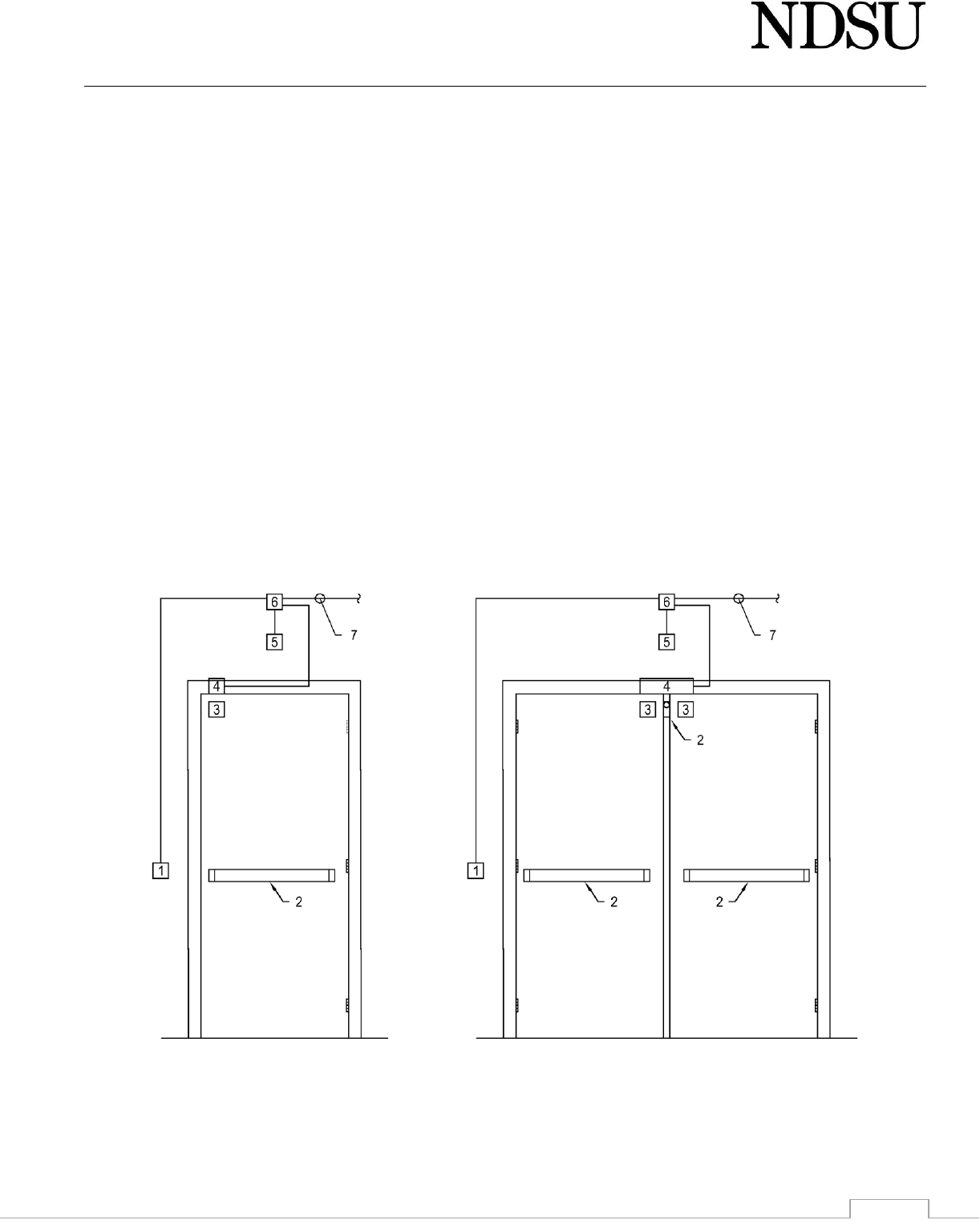
Design Guidelines Facilities Management
08-12
CARD ACCESS PREPARATION DETAIL FOR SINGLE OR DOUBLE CARD ACCESS READER DOORS WITH
MAGNETIC LOCK(S)
1) Card reader junction box centered at 42" above finished floor, on the non-secure side of the wall and with a 3/4" conduit to
#6.
2) Other locking hardware and/or locking accessories provided by hardware supplier. Locking hardware includes, but is not
limited to, cylindrical locks, mortise locks, exit devices and mullions.
3) Electrified Magnetic Lock provided with latch bond monitoring contacts, door positioning monitoring contacts and supplied
by the hardware supplier. See "Card Access Preparation Detail for Magnetic Locks" for more details.
4) Electrified junction box located in head of door frame above location magnetic lock is to be mounted with a 3/4" EMT
conduit connected to #6. This box and connecting conduit should be attached to door frame.
5) Low voltage junction box for request to exit switch provided by hardware supplier with 3/4" conduit to #6.
6) Low voltage 4" square extra deep junction box located on the secure side of the wall, in suspended ceiling space when
possible.
7) One-inch conduit home run from #6 to the squadron room. See "Card Access Preparation Detail for Squadron Equipment"
for more details.
• Electrified magnetic lock power supplies are to be mounted in squadron room. See "Card Access Preparation Detail for
Squadron Equipment" for more details.
• All conduits must comply with electrical codes for bend radii and have appropriate pull boxes.
• Magnetic hold opens on card access doors must be connected to card access system so that hold opens only operate when
door is unlocked. Depending on code requirements, they may also need to be tied into fire alarm system.

Design Guidelines Facilities Management
08-13
CARD ACCESS PREPARATION DETAIL FOR SINGLE OR DOUBLE CARD ACCESS MONITORED DOORS WITH
EXIT DEVICES THAT DON'T HAVE REQUEST TO EXIT AND/OR DOOR LATCH MONITORING
1) Card reader junction box centered at 42" above finished floor, on the non-secure side of the wall and with a 3/4" conduit to
#7 for future use. Blank cover supplied by Electrical Contractor.
2) Exit device(s) without request to exit and/or latch monitoring provided by hardware supplier. Complete door prep as if exit
device(s) are electrified exit devices with request to exit and/or latch monitoring. See either "Card Access Preparation Detail
for Exit Devices in Wood Doors" or "Card Access Preparation Detail for Exit Devices in Hollow Metal and Aluminum Doors"
for more information.
3) Keyed, removable mullion provided by hardware supplier.
4) Electrified hinge junction box located behind the electrified hinge with a 3/4" EMT conduit connected to #7. See "Card
Access Preparation Detail for Electrified Hinges in Hollow Metal and Aluminum Doors and Frames" or "Card Access
Preparation Detail for Electrified Hinges in Wood Doors" for more information.
5) Flush mounted magnetic monitoring switch. Make certain that preparation holes in door(s) and frame are not too large and
are circular in shape to ensure proper fit of magnet and magnetic switch. Magnetic switch(es) may not be glued in place.
See manufacturer's instructions for more information.
6) Electrified junction box located in head of door frame above location magnetic lock is to be mounted with a 3/4" EMT
conduit connected to #7 This box and connecting conduit should be attached to door frame.
7) Low voltage 4" square extra deep junction box located on the secure side of the wall, in suspended ceiling space when
possible.
8) One-inch conduit home run from #7 to the squadron room. See "Card Access Preparation Detail for Squadron Equipment"
for more details.

Design Guidelines Facilities Management
08-14
HANDICAPPED OPERATOR PREPARATION DETAIL FOR A DOUBLE DOOR WITH OR WITHOUT CARD
ACCESS
1) Card reader junction box centered at 42" above finished floor, on the non-secure side of the wall and with a 3/4" conduit to
#14. On doors without card access, this junction box and conduit can be omitted.
2) Four-inch square touchpad junction box centered at 42" above finished floor on the non-secure side of the wall with a 3/4"
conduit to #11.
3) Standard electrified hinge junction box located behind the electrified hinge with a 3/4" EMT conduit connected to #14. See
"Card Access Preparation Detail for Electrified Hinges in Hollow Metal and Aluminum Doors for more information.
4) Exit device with latch retraction provided by the hardware supplier. See either "Card Access Preparation Detail for Exit
Devices in Wood Doors" or "Card Access Preparation Detail for Exit Devices in Hollow Metal and Aluminum Doors" for more
information. Electric strikes will not be accepted without written approval from Owner.
5) Exit device on the second leaf of the pair of doors is to be electrified only if the door is an active door under the card access
system or both doors are controlled by handicapped operators. Whether the door is active or inactive, the preparation is
the same. See #4 for more information.
6) Four-inch square touchpad junction box centered at 42" above finished floor on the secure side of the wall with a 3/4"
conduit to #11.
7) Magnetic hold-open junction box if applicable with a 3/4" conduit to #12.
8) Magnetic hold-open hardware attached to door if applicable.
9) Keyed removable mullion provided by hardware supplier.
10) Electrical junction box located behind handicapped operator with a conduit to #13.
11) Low voltage 4" square junction box located behind the handicapped operator with 3/4" conduit to #14.
12) Outline of the handicapped operator. Verify the location with the supplier to ensure that the electrical and low voltage
junction boxes will be hidden by the handicapped operator header. Verify with Owner if the operator cover should extend
across the entire head of the door. If so, the closure for the inactive door should be a top jamb mounted closure and
installed inside handicapped operator cover.
13) Electrical junction box located on the secure side of the wall, in suspended ceiling space when possible with a conduit to
#15.
14) Low voltage 4" square extra deep junction box located on the secure side of the wall, in suspended ceiling space when
possible with a 3/4" conduit to #15.
15) Exit device power supply located on the secure side of the wall, in suspended ceiling space when possible as close to the
door as possible, mounted vertically. Mounted location must allow for obstruction-free access. Exit device power supply is
to be connected to #13 and #14 by conduit.
16) One-inch conduit home run from #14 to the squadron room. See "Card Access Preparation Detail for Squadron Equipment"
for more details.

Design Guidelines Facilities Management
08-15

Design Guidelines Facilities Management
08-16
HANDICAPPED OPERATOR PREPARATION DETAIL FOR A SINGLE DOOR WITH OR WITHOUT CARD ACCESS
1. Card reader junction box centered at 42" above finished floor, on the non-secure side of the wall and with a 3/4" conduit to
#12. On doors without card access, this junction box and conduit can be omitted.
2. Four-inch square touchpad junction box centered at 42" above finished floor on the non-secure side of the wall with a 3/4"
conduit to #8.
3. Exit device with latch retraction provided by the hardware supplier. See either "Card Access Preparation Detail for Exit
Devices in Wood Doors" or "Card Access Preparation Detail for Exit Devices in Hollow Metal and Aluminum Doors" for more
information. Electric strikes will not be accepted without written approval from Owner.
4. Electrified hinge junction box located behind the electrified hinge with a 3/4" EMT conduit connected to #12. See "Card
Access Preparation Detail for Exit Devices in Hollow Metal and Aluminum Doors" for more information.
5. Four-inch square touchpad junction box centered at 42" above finished floor on the secure side of the wall with a 3/4"
conduit to #8.
6. Magnetic hold-open hardware attached to door if applicable.
7. Electrical junction box located behind handicapped operator with a conduit to #11.
8. Low voltage 4" square junction box located behind the handicapped operator with 3/4" conduit to #12.
9. Outline of the handicapped operator. Verify the location with the supplier to ensure that the high and low voltage junction
boxes will be hidden by the handicapped operator header.
10. Magnetic hold-open junction box if applicable with a 3/4" conduit to #12.
11. Electrical junction box located on the secure side of the wall, in suspended ceiling space when possible with a conduit to
#13.
12. Low voltage 4" square extra deep junction box located on the secure side of the wall, in suspended ceiling space when
possible with a 3/4" conduit to #13.
13. Exit device power supply located on the secure side of the wall, in suspended ceiling space when possible as close to the
door as possible, mounted vertically. Mounted location must allow for obstruction-free access. Exit device power supply is
to be connected to #11 and #12 by conduit.
14. One-inch conduit home run from #12 to the squadron room. See "Card Access Preparation Detail for Squadron Equipment"
for more details.

Design Guidelines Facilities Management
08-17
CARD ACCESS PREPARATION DETAIL FOR DOUBLE CARD ACCESS READER OR TIMED DOORS WITH EXIT
DEVICES
1) Card reader junction box centered at 42" above finished floor, on the non-secure side of the wall and with a 3/4" conduit to
#6. This junction box and conduit can be omitted when both doors are timed doors.
2) Electrified hinge junction box located behind the electrified hinge with a 3/4" EMT conduit connected to #6. See "Card
Access Preparation Detail for Electrified Hinges in Hollow Metal and Aluminum Doors" for more information.
3) Electrified exit device provided by the hardware supplier. See either "Card Access Preparation Detail for Exit Devices in
Wood Doors" or "Card Access Preparation Detail for Exit Devices in Hollow Metal and Aluminum Doors" for more
information.
4) Keyed, removable mullion provided by hardware supplier.
5) Exit device on the second leaf of the pair of doors is to be electrified only if the door is an active door under the card access
system. Whether the door is active or in active the preparation is the same. See preparations mentioned in #3 for more
information.
6) Low voltage 4" square extra deep junction box located on the secure side of the wall, in suspended ceiling space when
possible with a 3/4" conduit to #8.
7) Electrical junction box located on the secure side of the wall, in suspended ceiling space when possible with a conduit to #6.
If exit device has an electrified trim, this junction box can be omitted.
8) Exit device power supply located on the secure side of the wall, in suspended ceiling space when possible as close to the
door as possible, mounted vertically. Mounted location must allow for obstruction-free access. Exit device power supply is
to be connected to #6 and #7 by conduit. If exit device has an electrified trim, the power supply should be located in
squadron room. See "Card Access Preparation Detail for Squadron Equipment" for more details.
9) One-inch conduit home run from #6 to the squadron room. See "Card Access Preparation Detail for Squadron Equipment"
for more details.
• All conduits must comply with electrical codes for bend radii and have appropriate pull boxes.
• Magnetic hold opens on card access doors must be connected to card access system so that hold opens only operate when
door is unlocked. Depending on code requirements, they may also need to be tied into fire alarm system.

Design Guidelines Facilities Management
08-18
CARD ACCESS PREPARATION DETAIL FOR SINGLE CARD ACCESS READER OR TIMED DOORS WITH EXIT
DEVICES
1. Card reader junction box centered at 42" above finished floor, on the non-secure side of the wall and with a 3/4" conduit to
#4. This junction box and conduit can be omitted for timed doors.
2. Electrified exit device provided by the hardware supplier. See either "Card Access Preparation Detail for Exit Devices in
Wood Doors" or "Card Access Preparation Detail for Exit Devices in Hollow Metal and Aluminum Doors" for more
information.
3. Electrified hinge junction box located behind the electrified hinge with a 3/4" EMT conduit connected to #4. See "Card
Access Preparation Detail for Electrified Hinges in Hollow Metal and Aluminum Doors and Frames" or "Card Access
Preparation Detail for Electrified Hinges in Wood Doors" for more information.
4. Low voltage 4" square extra deep junction box located on the secure side of the wall, in suspended ceiling space when
possible with a 3/4" conduit to #13.
5. Electrical junction box located on the secure side of the wall, in suspended ceiling space when possible with a conduit to #6.
If exit device has an electrified trim, this junction box can be omitted.
6. Exit device power supply located on the secure side of the wall, in suspended ceiling space when possible as close to the
door as possible, mounted vertically. Mounted location must allow for obstruction-free access. Exit device power supply is
to be connected to #4 and #5 by conduit. If exit device has an electrified trim, the power supply should be located in
squadron room. See "Card Access Preparation Detail for Squadron Equipment" for more details.
7. One-inch conduit home run from #4 to the squadron room. See "Card Access Preparation Detail for Squadron Equipment"
for more details.
• All conduits must comply with electrical codes for bend radii and have appropriate pull boxes.
• Magnetic hold opens on card access doors must be connected to card access system so that hold opens only operate when
door is unlocked. Depending on code requirements, they may also need to be tied into fire alarm system.

Design Guidelines Facilities Management
08-19
CARD ACCESS PREPARATION DETAIL FOR SINGLE CARD ACCESS READER DOOR WITH CYLINDRICAL LOCKS
1. Card reader junction box centered at 42" above finished floor, on the non-secure side of the wall and with a 3/4" conduit to
#6.
2. Electrified cylindrical lock provided by the hardware supplier. See either "Card Access Preparation Detail for Cylindrical
Locks in Wood Doors" or "Card Access Preparation Detail for Cylindrical Locks in Hollow Metal and Aluminum Doors" for
more information.
3. Minimum of 1/2" diameter path or conduit (depending on door composition) between #2 and #4.
4. Area of door that is prepped for electrified hinge. See either "Card Access Preparation Detail for electrified Hinges in Wood
Doors" or "Card Access Preparation Detail for electrified Hinges in Hollow Metal and Aluminum Doors and Frames" for more
information.
5. Electrified hinge junction box located behind the electrified hinge with a 3/4" EMT conduit connected to #6. See "Card
Access Preparation Detail for Electrified Hinges in Wood Doors" or "Card Access Preparation Detail for Electrified Hinges in
Hollow Metal and Aluminum Doors and Frames" for more information.
6. Low voltage 4" square extra deep junction box located on the secure side of the wall, in suspended ceiling space when
possible.
7. One inch conduit home run from #6 to the squadron room. See "Card Access Preparation Detail for Squadron Equipment"
for more details.
• Electrified cylindrical lock power supplies are to be mounted in squadron room. See "Card Access Preparation Detail for
Squadron Equipment" for more details.
• All conduits must comply with electrical codes for bend radii and have appropriate pull boxes.
• Magnetic hold opens on card access doors must be connected to card access system so that hold opens only operate when
door is unlocked. Depending on code requirements, they may also need to be tied into fire alarm system.

Design Guidelines Facilities Management
08-20
CARD ACCESS PREPARATION DETAIL FOR SINGLE CARD ACCESS MONITORED DOOR WITH CYLINDRICAL
LOCKS
1. Card reader junction box centered at 42" above finished floor, on the non-secure side of the wall and with a 3/4" conduit to
#6. Blank cover supplied by Electrical Contractor.
2. Cylindrical lock with request to exit provided by the hardware supplier. See either "Card Access Preparation Detail for
Cylindrical Locks in Wood Doors" or "Card Access Preparation Detail for Cylindrical Locks in Hollow Metal and Aluminum
Doors" for more information.
3. Minimum of 1/2" diameter path or conduit (depending on door composition) between #2 and #4.
4. Area of door that is prepped for electrified hinge. See either "Card Access Preparation Detail for Electrified Hinges in Wood
Doors" or "Card Access Preparation Detail for Electrified Hinges in Hollow Metal and Aluminum Doors and Frames" for more
information.
5. Electrified hinge junction box located behind the electrified hinge with a 3/4" EMT conduit connected to #6. See "Card
Access Preparation Detail for Electrified Hinges in Wood Doors" or "Card Access Preparation Detail for Electrified Hinges in
Hollow Metal and Aluminum Doors and Frames" for more information.
6. Low voltage 4" square extra deep junction box located on the secure side of the wall, in suspended ceiling space when
possible.
7. One-inch conduit home run from #6 to the squadron room. See "Card Access Preparation Detail for Squadron Equipment"
for more details.

Design Guidelines Facilities Management
08-21
CARD ACCESS PREPARATION DETAIL FOR SINGLE CARD ACCESS MONITORED DOOR WITH A CYLINDRICAL
LOCK THAT DOESN'T HAVE A REQUEST TO EXIT SWITCH
1. Card reader junction box centered at 42" above finished floor, on the non-secure side of the wall and with a 3/4" conduit to
#8 for future use. Blank cover supplied by Electrical Contractor.
2. Cylindrical lock without request to exit switch provided by the hardware supplier. Complete door prep as if cylindrical lock
in an electrified lockset with a request to exit switch. See either "Card Access Preparation Detail for Cylindrical Locks in
Wood Doors" or "Card Access Preparation Detail for Cylindrical Locks in Hollow Metal and Aluminum Doors" for more
information.
3. Minimum of 1/2" diameter path or conduit (depending on door composition) between #2 and #4. Complete door prep as if
cylindrical lock as a request to exit switch.
4. Area of door that is prepped for electrified hinge. Complete door prep as if cylindrical lock as a request to exit switch. See
either "Card Access Preparation Detail for Electrified Hinges in Wood Doors" or "Card Access Preparation Detail for
Electrified Hinges in Hollow Metal and Aluminum Doors and Frames" for more information.
5. Electrified hinge junction box located behind the electrified hinge with a 3/4" EMT conduit connected to #8. See "Card
Access Preparation Detail for Electrified Hinges in Wood Doors" or "Card Access Preparation Detail for Electrified Hinges in
Hollow Metal and Aluminum Doors and Frames" for more information.
6. Flush mounted magnetic monitoring switch. Make certain that preparation holes in door(s) and frame are not too large and
are circular in shape to ensure proper fit of magnet and magnetic switch. Magnetic switch(es) may not be glued in place. If
magnet is mounted into a piece of wood or other material, the wood or other material should be attached to door. See
manufacturer's instructions for more information.
7. Electrified junction box located in head of door frame above location magnetic lock is to be mounted with a 3/4" EMT
conduit connected to #8 This box and connecting conduit should be attached to door frame.
8. Low voltage 4" square extra deep junction box located on the secure side of the wall, in suspended ceiling space when
possible.
9. One-inch conduit home run from #8 to the squadron room. See "Card Access Preparation Detail for Squadron Equipment"
for more details. All conduits must comply with all electrical codes for bend radii and have appropriate boxes.

Design Guidelines Facilities Management
08-22
CARD ACCESS PREPARATION DETAIL FOR ELECTRIFIED HINGES IN WOOD DOORS
1. Minimum of 7/8" diameter hole with a minimum depth of 2".
2. Minimum of 3/4" diameter hole with a minimum depth of 4". This hole should also connect to the concealed path to the
cylindrical lockset or exit device.
3. Minimum of 3/4" diameter hole with a minimum depth of 4". Hole is to be centered between the bottom two hinge screws
and in line with the center of the other preparation holes.
• Verify the center location of the holes from Stanley CECS installation instructions.
• Follow manufacturer's instructions and comply with building codes when preparing all card access related work for all
current and future card access doors.
CARD ACCESS PREPARATION DETAIL FOR ELECTRIFIED HINGES IN WOOD FRAMES
1. Minimum of 7/8" diameter hole with a minimum depth of 2".
2. Minimum of 3/4" diameter hole with a minimum depth of 4". This hole should also connect to the concealed path to the
cylindrical lockset or exit device.
3. Single gang, 1 1/2" deep electrical box recessed into wood framing installed by electrical contractor before door frame is
installed. Center of box should be in line with the center of the electrified hinge. Verify the height of the electrified hinge
with the general contractor. The box should also be connected to the 3/4" conduit that is attached to the low voltage, 4"
square, extra deep junction box.
• Verify the center location of the holes from Stanley CECS installation instructions.
• Follow manufacturer's instructions and comply with building codes when preparing all card access related work for all
current and future card access doors.

Design Guidelines Facilities Management
08-23
CARD ACCESS PREPARATION DETAIL FOR CYLINDRICAL LOCKESTS IN WOOD DOOR
1. Minimum of 1" diameter hole extending a minimum of 4" beyond the back of the cylindrical lockset preparation.
2. Minimum of 1/2" diameter path between the lockset and electrified hinge.
3. Standard cylindrical latch bolt preparation.
4. Standard electrified cylindrical lockset preparation.
5. Standard 2 3/4" latch-bolt preparation.
CARD ACCESS PREPARATION DETAIL FOR EXIT DEVICES IN WOOD DOORS
1. Minimum of 7/8" diameter hole, with a minimum depth of 2".
2. Minimum of 3/4" diameter hole, with a minimum depth of 4".
3. Minimum of 3/4" diameter hole, with a minimum depth of 4". Hole to be in line with other prep holes and centered
between the bottom 2 hinge screws.
4. Minimum of 1/2" diameter path from #2 to the area behind the exit device.
5. Minimum of 3/4" diameter hole from the exit device side face of the door to #4.
6. Minimum of 1/2" deep by 1/2" wide groove from #5 to exit device manufacturers specified locations for the entry card
access wires to the exit device.
7. Hinge side mounting holes for the back of the exit device. These shall be through-bolted in all applications.
• Verify the center location of the holes from Stanley CECS installation instructions.
• Follow manufacturer's instructions and comply with building codes when preparing all card access related work for all
current and future card access doors.
• If exit device manufacturer requires a larger path anywhere in prep from hinge to exit device, comply with manufacturer's
requirements.

Design Guidelines Facilities Management
08-24
CARD ACCESS PREPARATION DETAIL FOR ELECTRIFIED HINGES IN HOLLOW METAL AND ALUMINUM
DOORS AND FRAMES
1. Minimum of 1" diameter burr-free hole.
2. Minimum of 3/4" diameter burr-free hole.
3. Minimum of 3/4" diameter path between the exit device and the hinge should be connected to this location. No conduit
should be necessary; the open style should be sufficient. For cylindrical locket applications, this path needs to be 1/2" EMT.
4. Electrical box with 3/4" conduit stub up 6" above top of frame.
5. Door electrical box for connecting 1/2" conduit for cylindrical lock applications. Electrical box is optional for exit device and
aluminum door applications.
• Verify the center location of the holes from Stanley CECS installation instructions.
• Electrical box and conduit are to be welded to the frame for all hollow metal frame applications. For aluminum frames, the
box and conduit should be connected to the steel angle hinge support.
• Unless authorized by Owner, all electrified hinges are the be 4 1/2"x4 1/2" Stanley CECS hinges.
• Mud boxes should not be installed behind the hinge supports that have card access electrical boxes attached to them.
• Ensure that there is a minimum of 1 1/2" clearance between the back of the hinge bracket and the inside of the electrical
box.
• Follow manufacturer's instructions and comply with building codes when preparing all card access related work for all
current and future card access doors.
CARD ACCESS PREPARATION DETAIL FOR CYLINDRICAL LOCKESTS IN HOLLOW METAL AND ALUMINUM
DOORS
1. Ensure that lock support allows for enough room for extra wire, connectors and temperature control module.
2. Minimum of 1/2" diameter EMT between the lockset and electrified hinge.
3. Standard cylindrical latch bolt preparation.
4. Standard electrified cylindrical lockset preparation.
5. Standard 2 3/4" latch-bolt preparation.

Design Guidelines Facilities Management
08-25
CARD ACCESS PREPARATION DETAIL FOR EXIT DEVICES IN HOLLOW METAL AND ALUMINUM DOORS
1. Minimum of 1" diameter burr-free hole.
2. Minimum of 3/4" diameter burr-free hole.
3. Minimum of 3/4" diameter path from #2 to the area behind the exit device hinge side mounting holes.
4. Minimum of 3/4" diameter hole through the exit device side face of the door at the manufacturer's specified location for
the entry of card access wires at the hinge side end of the exit device.
5. Hinge side mounting holes for the back of the exit device. These shall be through-bolted in all applications.
6. Steel reinforcement in hollow metal doors for hinge side exit device attachment.
7. Possible steel reinforcement inside door with #3.
• Verify the center location of the holes from Stanley CECS installation instructions.
• Follow manufacturer's instructions and comply with building codes when preparing all card access related work for all
current and future card access doors.

Design Guidelines Facilities Management
08-26
CARD ACCESS PREPARATION DETAIL FOR MAGNETIC LOCKS
1. Electrified magnetic lock provided by hardware manufacturer. This lock will be provided with latch bond and door position
monitoring contacts. Mount magnetic lock according to manufacturer's instructions.
2. Minimum of 3/4" diameter burr-fre hole. See magnetic lock manufacturer's instructions for location.
3. Electrical junction box located in head of door frame above location magnetic lock is the mounted with a 3/4" EMT conduit
stubbed up 6" above head of door frame. This box should be installed by door frame manufacturer.
4. Request to exit junction box located above center of door either in wall or mounted to suspended ceiling. Coordinate
location with owner electrician and/or locksmith.
• Electrical box and conduit are to be welded to a reinforcement steel plate for all hollow metal frame applications. For
aluminum frames, the box and conduit should be connected to a steel plate running along the entire head of door. Steel
plate is not only to attach electrical box and conduit but also a reinforcement plate for mounting the magnetic lock and the
closure's parallel arm shoe.
• Follow manufacturer's instructions and comply with building codes when preparing all card access related work for all
current and future card access doors.
• Hardware supplier is responsible for supplying any shims required to mount magnetic lock.

Design Guidelines Facilities Management
08-27
CARD ACCESS PREPARATION DETAIL FOR OVERHEAD CARD ACCESS MONITORED DOOR
1. Best key operated momentary dual direction door control switch for inside operation attached to a junction box centered at
42" above finished floor on the non-secure side of the wall with a 3/4" conduit to #5.
2. Card reader junction box centered at 42" above finished floor, on the non-secure side of the wall and with a 3/4" conduit to
#5 for future use. Blank cover supplied by Electrical Contractor.
3. High security surface mounted magnet monitoring switch with manufacturer supplied metallic conduit routed to #7.
4. Low voltage junction box located next to door operator's low voltage control box for future connection and with a 3/4" EMT
conduit to #7.
5. Overhead door operator's low voltage junction box with a 3/4" EMT conduit connected to #4.
6. Overhead door operator's motor.
7. Low voltage 4" square extra deep junction box located on the secure side of the wall, in suspended ceiling space when
possible.
8. One inch conduit home run from #7 to the squadron room. See "Card Access Preparation Detail for Squadron Equipment"
for more details.
• All conduits must comply with all electrical codes for bend radii and have appropriate pull boxes.
• Follow manufacturer's instructions and comply with building codes for the installation of overhead doors.

Design Guidelines Facilities Management
08-28
CARD ACCESS PREPARATION DETAIL FOR CARD ACCESS MONITORED ROOF HATCHES
1. High security surface mounted magnet monitoring switch with manufacturer supplied metallic conduit routed to #2.
2. Low voltage, 4" square junction box. Ensure box is located so conduit from #1 will reach junction box.
3. Three-quarter inch conduit home run from #2 to squadron room. See "Card Access Preparation Detail for Squadron
Equipment" for more details. Al conduits must comply with all electrical codes for bend radii and have appropriate pull
boxes. Electrical contractor may elect to install (2) 18 gauge, 4 conductor cables instead of card access cable specified for
the project.
4. Roof latch with padlock compatible with Best core.
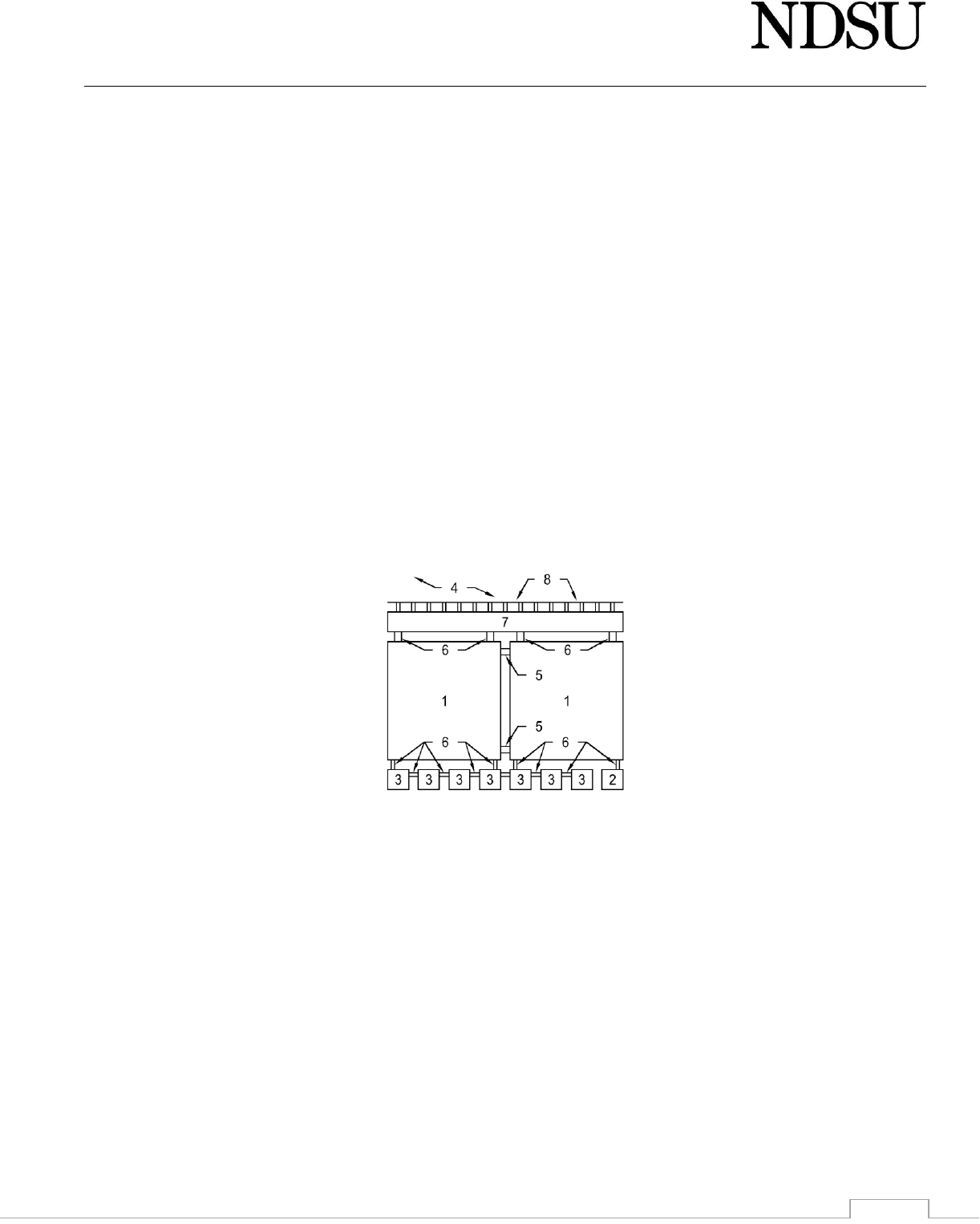
Design Guidelines Facilities Management
08-29
CARD ACCESS PREPARATION DETAIL FOR SQUADRON EQUIPMENT
1. Squadron cabinet(s) supplied and mounted by owner's electrician.
2. Squadron power supply supplied by owner and installed by electrical contractor.
3. Electrified cylindrical lock, electrified exit device lever trim, and/or magnetic lock power supplies if applicable. These
power supplies are supplied by hardware supplier and installed by electrical contractor.
4. All squadron equipment to be mounted on a 3/4" piece of gray painted plywood provide by electrical contractor. Size
plywood to allow of future expansion.
5. Large conduit provided and installed by the electrical contractor to connect large J box or wire trough to squadron cabinet
(minimum of 3” EMT)
6. Low voltage connecting conduits (min of 1” EMT)
7. Large junction box or wire trough provided and installed by the electrical contractor to terminate all of the #8s.
8. 1" conduit home runs from each of the card access doors terminated into #7.
• All material (conduit, connectors, plywood, large junction box, or wire trough) to connect squadron cabinet will be provided
and installed by the electrical contractor.
• All card access related power supplies are to be on dedicated emergency circuit and preferably on dedicated generator
emergency circuits where available.
• Provide an extra loop of 10' beyond entry of cars access squadron cabinet.
• Clearly label cables on both ends with description of location including door number.
• All conduits are to be EMT. No flexible conduit will be accepted.
• Extra card access wire is to be left in the squadron room.

Design Guidelines Facilities Management
09-1
Finishes
09 05 00 Common Work Results for Finishes
1) Ceiling and floor tile, carpet, paint, wood floors, ceramic tile, etc., must have the same batch number when
ordering each product in bulk.
A) Extra quantities of the aforementioned products shall be made available to the Owner in quantities shown
in 01 78 44 for future use to replace damaged materials.
B) Discontinued batches or materials will not be accepted.
2) All interior hollow metal frames shall be caulked to drywall after finish coat of paint. Caulk shall match paint
color of the door frame.
09 20 00 Plaster and Gypsum Board
1) Plastered surfaces should be used in restrooms and residence halls.
2) Specify only 0.625” (5/8”) gypsum wallboard throughout the project and require fastening the studs entire
height.
3) Specify high-density gypsum wallboard for all corridors, dining areas, storage rooms, residence halls,
classrooms, and other high-use areas. Must be installed to a height of 48”.
4) All drywall to be installed horizontally.
5) A minimum of three coats of taping compound is needed on all walls and ceilings.
6) Tape and compound shall be used on corner beads; corner beads shall be screwed in, not crimped.
7) All taping compound shall be feathered out.
8) Notification is required prior to priming to inspect the taping surfaces first.
9) See section 05 40 00 for Metal Framing requirements.
09 51 00 Acoustical Ceilings
1) Use lay in acoustical ceiling tile to provide better access to the building utilities. Use 2’X2’ lay in acoustical ceiling
tile with beveled edges to provide better access to the building utilities.
2) Suspended ceilings would be best in laboratory and office areas. Confer with the Owner when making this
determination.
3) Acoustical plaster and acoustical ceiling tile should not be within touch without the use of a ladder to avoid
damage to the finished surface. Minimum height of eleven (11) feet when using this type of material on common
area ceilings in resident halls. Provide proper conditions above freezing when applying plaster. Include access
panels in all plaster ceiling, where feasible, to provide access to mechanical pipe, duct work, etc.
09 60 00 Flooring
1) On high traffic areas, use ceramic tile, quarry tile, epoxy, or other hard surface flooring, to provide an easily
maintained surface.
2) The base material shall be inspected by the Consultant prior to installation of the floor system to ensure
expansion joints are provided to prevent cracking of floor covering due to settlement and noticeable failure.
3) Carpet tile shall be used in classrooms, student rooms, etc., with a minimum four inch vinyl base.
4) Restroom flooring shall be a poured, seamless epoxy surface or ceramic tile and shall extend up wall to a height
of 4”.
5) Epoxy floors shall have UV protection installed as part of the system.
09 68 00 Carpet
1) Pile shall be solution/yarn dyed with a minimum of 26 ounces.
2) Primary backing shall be woven polypropylene, high performance moisture barrier; secondary backing shall be
“HP (High Performance)”.
3) Fiber shall be 100% Invista Antron Legacy, Lumena, or Ultron Type 6.6 nylon
4) Install carpet using the manufacturer’s recommended adhesive applied at the manufacturer’s recommended
spread rate.
5) Seam Seal all seams within the field of the carpet using the manufacturer’s approved product.
6) All carpet shall be installed having a tight fit against all surfaces.
7) Carpet shall be installed so as to minimize the overall lineal footage of seams required. Consider locating seams

Design Guidelines Facilities Management
09-2
in order to maximize the useful life of carpet.
8) Ceiling and floor tile, carpet, paint, wood floors, etc., must have the same batch number when ordering each
product in bulk. Extra quantities of the aforementioned products shall be made available to the Owner, at five
(5) percent of the facilities total use, for future use to replace damaged materials. Discontinued batches or
materials will not be accepted.
09 70 00 Wall Finishes
1) Provide washable finishes on all surfaces.
A) On corridor walls, use either glazed brick, ceramic tile, or marble, which can be maintained with the least
amount of effort.
B) Vinyl wall covering is not allowed.
2) An easily cleanable, washable base material, a minimum four (4) inches high, should be installed throughout.
3) When applying wood paneling over drywall or plaster, place joints on the center of stud and off the drywall joint
to accommodate nailing.
4) A hard-wearing washable surface shall be provided on walls in classrooms, especially beneath instructional
boards.
5) In shower and drying room installations, provide glazed block on walls with cement plaster ceiling.
09 90 00 Painting and Coating
1) All paints shall be zero VOC.
2) Paint includes coating system materials, primers, emulsions, enamels, stains, sealers and fillers, and other
applied materials whether used as prime, intermediate, or finish coats. Owner maintains a record of colors used
throughout the campus which is to be complied with for renovation projects.
3) The eggshell paint grade shall be 100% Acrylic Latex. Verify with SDS that the paint contains not less than 30%
solids.
4) Eggshell paint shall be used for hollow metal doors and frames.
5) Surface temperature shall not be less than 60° Fahrenheit for paint or stain application.
6) Varnish shall be a polyurethane composition for durability and quick drying periods. A compatible sealer is to
be used on all varnished surfaces. Two finish coats of varnish shall be applied. Fill nail holes before final coat.

Design Guidelines Facilities Management
10-1
Specialties
10 11 00 Visual Display Surfaces
1) All white boards and cork boards shall be mechanically fastened onto walls; gluing will not be allowed.
2) Support system:
A) Extruded aluminum, 6061-T6 alloy, support keys securely mounted through continuous galvanized
mounting strips on back of unit.
B) Units over 13 inches high have 2 pair of support keys 5 modules apart vertically to allow height adjustment.
C) Support keys interface horizontal support rail.
D) Stand-off extrusion is provided on each unit to hold vertical surface parallel to wall surface.
3) Markerboard: Porcelain enamel on steel, minimum 26 gauge, laminated to 3/4 inch thick particleboard core
using water-proof adhesives.
A) Markerboard to be a minimum of 4’-0” tall, mounted at 3’-0” above finished floor.
4) Tackboard: 1/4 inch thick tac-tex vinyl impregnated cork laminated to 1/2 inch thick particleboard core using
water-proof adhesives.
5) Back surface sealed with 0.015 aluminum moisture barrier. Radius corners 2 inches. Edges finished with PVC
with custom overhang lip.
6) Stiffen boards to minimize flexing.
10 13 00 Directories
A) Provided and installed by Owner.
10 14 00 Signage
1) Room and wayfinding signage provided and installed by Owner.
2) Buildings and the departments within are identified by the NDSU supplied stand-alone green building sign. The
colors used shall be:
A) Pantone 342 Green
B) Pantone 123 Yellow
3) No logo or discipline signa is to be installed or applied to a building’s exterior.
4) If lettering is to be installed, it shall be six (6) inch cast aluminum with a matte edge and clean anodized finish
such as #507 Heavy Ribbon style, provided by A.R.K. Ramos. Owner will provide electronic file of the text to the
contractor to use for ordering exterior lettering.
5) Final room identification and numbers will be provided by the Owner.
A) The Owner’s room numbering are the record numbers that the mechanical Building Control Unit and the
electrical panels will use.
B) Signage shall be manufactured by Orbus, Vista or approved equal.
6) For building Plaque requirements, see Exhibit E-12.
10 28 00 Toilet and Bath Accessories
1) Toilet and bath partitions
A) Toilet partitions shall be floor mounted and urinal partitions shall be wall mounted.
1) All partitions shall use manufacturer’s torx drive fasteners.
B) All hardware shall be manufacturer’s heavy duty aluminum.
C) Latch and keepers shall be surface mounted, bolt-type.
D) Standard manufacturer’s stainless steel hinges may be used on steel partitions; stainless steel piano hinges
are to be used on solid-polymer partitions.
E) Partitions shall be 69” tall or manufacturers high/tall version.
F) Partitions with no gaps shall be provided.
2) Dispensers
A) NDSU will supply liquid soap dispensers, surface mounted paper towel dispensers and waste paper
containers. Items shall be installed by contractor.
1) The paper towel dispensers are 14.65” H x 13.26” W x 8” D.
2) The trash cans are 18.25” H x 12.5” W x 16.25” D.
3) Review the best possible location for these items to maintain ADA compliance in all restrooms.

Design Guidelines Facilities Management
10-2
B) The contractor shall furnish the following restroom accessories made of stainless steel with a No. 4 satin
finish:
1) Surface mounted two-roll toilet paper dispensers, one per toilet stool (Impact Products Model 2501)
2) Partition mounted sanitary napkin receptacles, one per women’s stall (Rubbermaid Model 6140)
3) Surface mounted channel frame mirror sized to cover china basin(s) without a break
C) Verify current product with the Owner’s Associate Director.
3) Shelving
A) Where possible, a shelf near the bathroom entrance shall be provided.
10 44 00 Fire Protection Specialties
1) Fire Extinguisher: Provide 10 pound ABC all-purpose extinguishers (Minimum 3-A: 40-B:C) in each fan, elevator
machine, and mechanical equipment room.
2) In public areas, use 5 pound ABC all-purpose fire extinguisher (Minimum 2-A: 10-B:C).
A) Install the fire extinguishers in recessed wall cabinets equipped with theft resistant, replaceable plastic locks
and an acrylic plastic window.
B) Key all boxes alike.
C) The glass shall be transparent enabling the owner to view extinguisher pressure gauge.

Design Guidelines Facilities Management
11-1
Equipment
11 21 23 Vending Equipment
1) Program areas for vending machines including data connections, power, and proper ventilation.
11 52 13 Projection Screens
1) Da Lite model E800-11 shall not be used.

Design Guidelines Facilities Management
12-1
Furnishings
12 20 00 Window Treatment
1) Blinds or shades are to be installed in all exterior windows; discuss with Owner regarding window treatment of
interior windows.
2) Standard design shall be based on (Architect may consult Owner with alternatives):
Brand
Hunter Douglas
Material
.008 Gauge Aluminum
Slat Size
1”
Color
#002 Alabaster
Style
“Lightlines”
12 30 00 Manufactured Casework
1) See also section 06 41 00.
2) Manufacturers who wish to supply cabinetry must be approved prior to the bid by submitting a sample that
meets the requirements in the casework specifications (Sections 06 41 00 and 12 30 00). Consult the Owner’s
Cabinet Shop prior to specifying this section.
3) Design cabinets to be impermeable to anticipated corrosive materials and liquids.
4) Flammable storage cabinets shall have self-closing hinges.
5) Casework used for teaching stations shall be ADA compliant.
12 31 00 Manufactured Metal Casework
Part 1 - General
1) Description
A) This section specifies metal casework and related accessories, including base cabinets, wall cabinets, and
full height cabinets.
B) Items specified in this section:
1) Laboratory and Hospital Casework: Prefixed by "VL" AND "M", including metal casework of the
following types:
a) Wardrobe Cabinet, Metal, 5A (SD123100-02)
b) Wall Cabinet, Metal, 5B (SD123100-01).
2) Related Work
A) Color of casework finish: Section 09 06 00, SCHEDULE FOR FINISHES.
B) Electrical Components: Division 26, ELECTRICAL.
3) Quality Assurance
A) Approval by Contracting Officer of proposed manufacturer, or suppliers, will be based upon submission by
Contractor certification that, manufacturer regularly and presently manufactures casework specified as
one of their principal products.
B) Installer has technical qualifications, experience, trained personnel, and facilities to install specified items.
C) Furnish supervision of installation at construction site by a qualified technician regularly employed by
casework installer.
4) SUBMITTALS
A) Submit in accordance with Section 01 33 23, SHOP DRAWINGS, PRODUCT DATA, AND SAMPLES.
B) Certificates:
1) Manufacturer's Certificate of qualifications specified and finish on casework.
2) Contractor's Certificate of installer’s qualifications specified.
3) Safety glass meets requirements of ANSI Standard Z97.1.
C) Manufacturer's Literature and Data:
1) Brochures showing name and address of manufacturer, and catalog or model number of each item
incorporated into the work.
2) Manufacturer's illustration and detailed description.
3) List of deviations from contract specifications.
4) Locks, each kind
D) Shop Drawings (1/2 Full Scale):

Design Guidelines Facilities Management
12-2
1) Showing details of casework construction, including kinds of materials and finish, hardware,
accessories and relation to finish of adjacent construction, including specially fabricated items or
components.
2) Fastenings and method of installation.
3) Location of service connections and access.
E) Samples:
1) Metal plate, 6” square, showing chemical resistant finish, in each color.
2) One complete casework assembly, including cabinet(s) with drawers and cupboard.
3) One glazed sliding door with track and pertinent hardware. A complete cabinet may be submitted to
fulfill this requirement.
4) Cabinets for subsequent installation may be submitted for above requirements.
5) APPLICABLE PUBLICATIONS
A) Publications listed below form a part of this specification to extent referenced. Publications are
referenced in the text by basic designation only.
B) American Society for Testing and Materials (ASTM):
1) A36/A36M-08 Carbon Structural Steel
2) A167-99(R 2009) Stainless and Heat-Resisting Chromium Steel Plate Sheet and Strip
3) A283/A283M-03(R 2007) Low and Intermediate Tensile Strength Carbon Steel Plates
4) A568/A568M-09 Steel, Sheet, Carbon and High-Strength, Low-Alloy Hot-Rolled and Cold-Rolled,
General Requirements
5) A794/A794M-09 Standard Specification for Commercial Steel (CS), Sheet, Carbon (0.16% Maximum
to 0.25% Maximum) Cold Rolled
6) B456-03(R2009) Electrodeposited Coatings of Copper Plus Nickel Plus Chromium and Nickel Plus
Chromium
7) C1036-06 Flat Glass
C) American National Standard Institute:
1) Z97.1-09 Safety Glazing Material used In Buildings
D) Builders Hardware Manufacturers Association (BHMA):
1) A156.1-06 Butts and Hinges
2) A156.9-10 Cabinet Hardware
3) A156.5-10 Auxiliary Locks and Associated Products
4) A156.11-10 Cabinet Locks
5) A156.16-02 Auxiliary Hardware
E) American Welding Society (AWS):
1) D1.1-10 Structural Welding Code Steel
2) D1.3-08 Structural Welding Code Sheet Steel
F) National Association of Architectural Metal Manufacturers (NAAMM):
1) AMP 500-505-06 Series Metal Finishes Manual
G) U.S. Department of Commerce, Product Standard (PS):
1) PS 1-95 Construction and Industrial Plywood
H) Federal Specifications (Fed. Spec.):
1) FF-N-836D Nut, Square, Hexagon Cap, Slotted, Castle Knurled, Welding and Single Ball Seat
2) A-A-55615 Shield, Expansion; Nail Expansion (Wood Screw and Lag Bolt Self-Threading
Anchors)
Part 2 – Products
1) Materials
A) Sheet Steel:
1) ASTM A794, cold rolled, Class 1 finish, stretcher leveled.
2) Other types of cold rolled steel meeting requirements of ASTM A568 may be used for concealed
parts.
B) Structural Steel: ASTM A283 or ASTM A36.
C) Stainless Steel: ASTM A167, Type 302B.
D) Glass:
1) ASTM C1036 Type I, Class 1, Quality q3,

Design Guidelines Facilities Management
12-3
2) For Doors: 1/4” thick; except where laminated glass is shown.
3) For shelves: Either 1/4” or 3/8” thick.
E) Laminated Glass:
1) Fabricate of two sheets of 1/8” thick clear glass, laminated together with a 0.060” thick vinyl
interlayer, to a total overall thickness of 5/16”.
F) Glazing Cushions:
1) Channel shaped, of rubber, vinyl or polyethylene plastic, with vertical flanges not less than 3/32”
thick and horizontal web 1/8” thick.
2) Flanges may have bulbous terminals above the glazing heads or terminate flush with top of beads.
G) Plywood:
1) Prod. Std. PS 1, seven ply, interior.
2) Where both sides are exposed, use Grade AA.
3) Grade AB for other uses.
H) Fasteners:
1) Exposed to view, chrome plated steel or stainless steel, or finished to match adjacent surface.
2) Use round head or countersunk fasteners where exposed in cabinets.
3) Expansion Bolts: Fed Spec. A-A-55615. Do not use lead or plastic shields.
4) Nuts: Fed Spec FF-N-836. Type III, Style 15 where exposed.
5) Sex Bolts: Capable of supporting twice the load.
2) MANUFACTURED PRODUCTS
A) When two or more units are required, use products of one manufacturer.
B) Manufacturer of equipment assemblies, which include components made by other, shall assume
complete responsibility for the final assembled unit.
C) Constituent parts which are alike, use products of a single manufacturer.
3) CASEWORK FABRICATION
A) General:
1) Welding: Comply with AWS Standards.
2) Reinforce with angles, channels, and gussets to support intended loads, notch tightly, fit and weld
joints.
3) Constructed of sheet steel, except where reinforcing required.
B) Minimum Steel Thickness:
1) 20 gage - Drawer fronts, backs, bodies, closure plates or scribe and filler strips less than 3” wide,
sloping top, shelf reinforcement channel and shelves. Toe space or casework soffits and ceilings
under sloping tops.
2) 18 gage - Base pedestals, casework top sides, back, and bottom panels, closure scribe and filler strips
3” or more. Reinforcement for drawers with locks. Tables legs, spreaders and stretchers, when
fabricated of cold rolled tubing. Metal for desks; except legs and aprons. Door exterior and interior
panels, flush or glazed. Cross rails of base units. Front bottom rails, back bottom rails; rails may be 16
gage thick. Uprights or posts. Top corner gussets.
3) 16 gage - Aprons, apron division, reinforcing gussets, table legs, desk legs and aprons, spreaders and
stretchers when formed without welding. Toe base gussets, drawer slides, and other metal work.
Front top rails and back rails except top back rails may be 1.2 mm (0.047 inch) (18 gage) thick.
4) 14 gage - Drawer runners door tracks.
5) 12 gage - Base unit bottom corner gussets and leg sockets.
6) 11 gage - Reinforcement for hinge reinforcement inside doors and cabinets.
C) Casework Construction:
1) Welded assembly.
2) Fabricate with enclosed uprights or posts full height or width at front, include sides, backs, bottoms,
soffits, ceilings under sloping tops, headers and rail, assembled to form an integral unit.
3) Form sides to make rabbeted stile 3/4” to 1-1/8” wide, closed by channel containing shelf adjustment
slots.
4) Make bottom of walls units flush, double panel construction.
5) Make top and cross rails of "U" shaped channel.
6) Provide enclosed backs and bottoms in cabinets, including drawer units.

Design Guidelines Facilities Management
12-4
7) Provide finish panel on exposed cabinet backs.
8) Do not use screws and bolts in construction or assembly of casework, except to secure hardware,
applied door stops, accessories, removable panels and where casework is required to be fastened
end to end or back to back.
9) Fabricate casework, except benches, and desks with finished end panels.
10) Close flush exposed soffits of wall hung shelving, knee spaces in counters, and toe spaces at bases.
11) In base units with sinks provide one piece, lowered backs.
a) If a soil trap is required, no bottom shelf shall be installed to allow for trap removal.
12) In base units with doors provide removable backs.
13) Provide built-in raceways or tubular or channel shaped members of casework for installation of wiring
and electric work. Mount junction boxes on rear of cabinets, Electric work is specified in electrical
sections of specifications.
14) Provide reinforcing for hardware.
15) Size Dimensions:
a) Used dimensions shown or specified within tolerances specified.
b) Tolerance:
i) Depth: 13” in lieu of 12”, 18” in lieu of 16”, except wall hung units above counter. 21” to 24”
in lieu of 22”.
ii) Width: Minus 1”.
iii) Height: 1” plus or minus for wall hung cabinets and counter mounted cabinets, excluding
sloping tops. 1” plus for floor standing cabinets, excluding base and sloping tops. Full height
cabinets shown back to back same height.
iv) Manufacturer's tolerance for the same length, depth or height: Not to exceed 0.0625”.
D) Base Pedestals:
1) Provide adjustable leveling bolts accessible through stainless steel plugs, or notch in the base
concealed when resilient base is applied.
2) Except where flush metal base is shown, provide toe space at front recessed 3”.
E) Doors:
1) Hollow metal type, flush and glazed doors not less than 5/8” thick.
2) Fabricate flush metal doors of two panels formed into pans with corners welded and ground smooth.
Provide flush doors with a sound deadening core.
3) Fabricate glazed metal doors with reinforced frame and construct either from one piece of steel, or
have separate stiles and rails mitered and welded at corners, and welds ground smooth.
a) Secure removable glazing members with screws to back of doors.
b) Install glass in rubber or plastic glazing channels.
4) Provide sheet steel hinge reinforcement inside doors.
5) Sliding doors: Provide stops to prevent bypass.
6) Doors removable without use of tools except where equipped with locks.
F) Drawers:
1) Drawer fronts flush hollow metal type not less than 5/8” thick with sound deadening core. Fabricate
of two panels formed into pans. Weld and grind smooth corners of drawer fronts.
2) Form bodies from one piece of steel, weld to drawer front.
3) Provide reinforcement for locks and provide rubber bumpers at both sides of drawer head to cushion
closing.
4) Equip with roller suspension guides.
G) Sloping Tops:
1) Provide sloping tops for casework where shown.
2) Where ceilings interfere with installation of sloping tops. Provide filler plates as specified.
3) Omit sloping tops or filler plates whenever ceiling material is turned down and furred-in at face of
casework.
4) Provide exposed ends of sloping tops with flush closures.
5) Fasten sloping tops with sheet metal screws inserted from cabinet interior; space fastener as
recommended by manufacturer.
H) Shelves:

Design Guidelines Facilities Management
12-5
1) Capable of supporting an evenly distributed minimum load of 25 pounds per square foot without
visible distortion.
2) Flange shelves down 3/4” on edges, with front and bearing edges flanged back 1/2”.
3) For shelves over 42” in length and over 12” in depth install 1-1/2” x ½” x 0.0359 thick sheet steel hat
channel reinforcement welded to underside midway between front and back and extending full
length of shelf.
4) Weld shelves to metal back and ends unless shown adjustable.
5) Provide means of positive locking shelf in position, and to permit adjustment without use of tools.
6) On pharmacy or sloping shelf provide 1/2” wide clear acrylic plastic raised edge, 1/8” thick, secured
to front edge of shelf.
I) Undercounter Table and Bench Frames:
1) Using welded construction.
2) Open frame type with aprons and legs when required.
3) Aprons:
a) Channels shaped welded at corners, with leg sockets and reinforcing triangular corner gussets
welded in corners.
b) Pierce sockets to receive leg bolts and notch gussets to receive legs.
c) Upper flange perforated or slotted to receive screws at 8” centers, and back channels when
installed against wall. Size slots for 1/4” anchor bolts.
d) Pierce aprons to receive drawer formation, rail at top of drawer opening. Install channel shaped
apron division welded at ends, 30” apart to front and back aprons, or at each side of drawer.
e) Fabricate metal components from sheet steel.
i) Use 1.5 mm (0.0598”) thick sheet for gussets and channel aprons.
ii) Use 1.2 mm (0.0478”) thick sheet for other items.
f) At knee space, provide exposed metal sides and metal closure plate for soffit. Where shown at
knee space, provide exposed metal back secured with continuous angle closures at both side.
4) Legs:
a) Cold rolled tubing or 1.5 mm (0.0598”) formed steel.
b) Leveling-anchoring device at floor.
c) Stud bolt at top for attachment to leg socket.
5) Leg Braces:
a) Tables and benches not anchored to walls.
b) Brace back against front legs near bottom with steel angle, channel or tubular braces.
c) Fasten braces together with steel straps.
6) Leg Shoes:
a) Fit laboratory casework legs at bottom with either stainless steel, aluminum, or chromium plated
brass shoes, not less than 1” in height.
b) Fit other legs with a movable molded vinyl shoe 4” high and coved at bottom.
J) Closures and Filler Strips at Pipe Spaces:
1) Flat steel strips or plates.
2) Openings less than 8” wide: 1.2 mm (0.047”) thick.
3) Openings more than 8” wide: 0.9 mm (0.359 inches) wide.
4) ACCESSORIES
A) Card or Label Holders for Shelves:
1) Fabricate of 0.6 mm (0.0239 inch) thick steel approximately 5” long, or continuous where shown,
having top and bottom edges bent over on face and welded to shelf.
2) Finish exposed surfaces in same color as shelf.
B) Label Holders for Doors and Drawers:
1) Cast or wrought brass or aluminum, 2” by 3-1/2”.
2) Fasten to casework as recommended by manufacturer.
C) Shadow Boards in Cabinet VL 33:
1) Plywood of size and thickness shown with exposed edges chamfered.
2) Secure boards to back of exterior metal doors and cabinet back with screws.
3) Use pivot top and bottom hinges on intermediate boards with pulls on each leaf.

Design Guidelines Facilities Management
12-6
4) Paint exposed surfaces of shadow boards with two shop coats of shellac.
5) HARDWARE
A) Factory installed.
B) Exposed hardware, except as specified otherwise, satin finished chromium plated brass or nickel plated
brass or anodized aluminum.
C) Cabinet Locks:
1) Where locks are shown.
2) Locked pair of hinged door over 900 mm (36 inches) high:
a) ANSI/BHMA A156.5, similar to E0261, Key one side.
b) On active leaf use three-point locking device, consisting of two steel rods and lever controlled
cam at lock, to operate by lever having lock cylinder housed therein.
c) On inactive leaf use dummy lever of same design.
d) Provide keeper holes for locking device rods and cam.
e) Use two point locking device both doors of cabinet 6D similar to ANSI/BHAMA A156.5, E0251,
key one side.
3) Door and Drawer: ANSI/BHMA A156.11 cam locks.
a) Drawer and Hinged Door up to 36” high: E07261.
b) Pin-tumbler, cylinder type lock with not less than four pins. Disc tumbler lock "duo A" with brass
working parts and case, as manufactured by Illinois Lock Company are acceptable.
c) Sliding Door: E07161.
4) Key locks differently for each type casework and master key for each service, such as Nursing Units, //
Psychiatric, // Administrative, // Pharmacy //.
a) Key drug locker inner door different from outer door.
b) Provide two keys per lock.
c) Provide six master keys per service or Nursing Unit.
5) Marking of Locks and Keys:
a) Name of manufacturer, or trademark which can readily be identified legibly marked on each lock
and key change number marked on exposed face of lock.
b) Key change numbers stamped on keys.
c) Key change numbers to provide sufficient information for manufacturer to replace key.
D) Cabinet Hardware: ANSI BHMA A156.9.
1) Door/Drawer Pulls: B02011.
a) One for drawers up to 23” wide.
b) Two for drawers over 23” wide.
c) Sliding door flush pull, each door: B02201.
2) Door in seismic zones: B03352.
a) Do not provide thumb latch on doors equipped with three point locking device.
b) Use lever operated two point latching device on paired doors over 36” high if three point locking
or latching device is not used.
3) Cabinet Door Catch:
a) Install at bottom of wall cabinets, top of base cabinets and top and bottom of full height cabinet
doors over 48”.
b) Omit on doors with locks.
4) Drawer Slides:
a) Use B05051 for drawers over 6” deep.
b) Use B05052 for drawers 3” to 6” deep.
c) Use B05053 for drawers less than 3” deep.
5) Butt Hinges:
a) B01351, minimum 1.8 mm (0.072 inch) thick chrome plated steel leaves.
b) Minimum 3.5 mm (0.139 inch) diameter stainless steel pins.
c) Full mortise type, five knuckle design with 2-1/2” high leaves and hospital type tips.
d) Two hinges per door except use three hinges on doors 48” and more in height. Use stainless steel
leaves for tilting bin doors.
e) Do not weld hinges to doors or cabinets.

Design Guidelines Facilities Management
12-7
6) Pivot hinges:
a) ANSI/BHMA A156.1 A875B.
7) Shelf Supports:
a) Install in casework where adjustable shelves are noted.
b) Adjustable Shelf Standards: B04061 with shelf rest B04081.
c) Vertical Slotted Shelf Standard: B04102 with shelf brackets B04112 sized for shelf depth.
8) Sliding Doors:
a) Doors supported by two ball bearing bronze or nylon rollers or sheaves riding on a stainless steel
track.
b) Sliding Door Tracks: B07093. Plastic tracks not acceptable.
c) Doors restrained by a nylon, polyvinylchloride, or stainless steel guide at opposite end.
9) Auxiliary Hardware:
a) ANSI A156.16.
10) Door silencers:
a) LO3011 or LO3031.
b) Install two rubber bumpers each door.
c) Silencers set near top and bottom of jamb.
11) Closet Bar:
a) L03131 chrome finish of required length.
6) METAL FINISHES
A) Comply with NAAMM 500 series and as specified.
B) Steel Cabinets including Closures and Filler Strips:
1) Acid resisting finish except hardware and stainless steel.
2) After fabrication of cabinet submerge in a degreasing bath, and thoroughly rinse to remove dirt and
grease, and other foreign matter.
3) Apply non-metallic phosphate coating, then finish with baked-on acid resisting enamel not less than
one mil thick.
4) Finish resistant to action of the following reagents when 10 drops (0.5 cm3) are applied to the surface
and left open to the atmosphere for period of one hour:
Hydrochloric Acid 37 percent Ethyl Alcohol
Phosphoric Acid 75 percent Methylethyl Keytone
Sulfuric Acid 25 percent Acetone
Glacial Acetic Acid Ethyl Acetate
Sodium Hydroxide 10 percent Ethyl Ether
Sodium Hydroxide (concentrated) Carbon Tetrachloride
Ammonia Hydroxide (concentrated) Xylene
Hydrogen Peroxide 5 percent Phenol 85 Percent
Formaldehyde 37 percent
5) Color of finish is specified in Section, INTERIOR/EXTERIOR FINISHES, MATERIALS, AND FINISH
SCHEDULES.
C) Brass:
1) U.S. Standard Finish No. 26 for hardware items.
2) Other brass items: ASTM B456, chromium plated finish meeting requirements for Service Condition
SCI.
D) Aluminum:
1) Chemically etched medium matte, clear anodic coating, Class II, Architectural, 0.4 mils thick.
E) Stainless Steel:
1) Mechanical finish No. 4 on sheet except No. 7 on tubing.
7) DISPENSING TRAYS AND BINS
A) Design trays and bins to fit cabinets where shown.
B) Fabricate of steel, polypropylene, fiberglass reinforced polyester resin, or other suitable material.
C) Lock securely in place without the use of tools.
D) Fit at angle to provide gravity feed where shown.
E) Dispensing Trays:

Design Guidelines Facilities Management
12-8
1) Equip trays with two longitudinal dividers adjustable to three position.
2) Approximate dimensions: 6” in width 3” in depth, and length to suit cabinet’s depth furnished.
F) Dispensing Bins:
1) Open front, except for retaining rim.
G) Approximate dimensions: 6” in width, 5” in depth, and length to suit cabinets furnished.
8) ELECTRICAL FIXTURES
A) Comply with requirements of Division 26 – ELECTRICAL specifications for fixtures, receptacles, wiring and
junction boxes required for fixtures and receptacles, included with casework.
B) Suitable for use with electrical system specified and shown.
C) Factory install in casework.
9) VL 33
A) Construct as shown.
B) Use pivot hinges on center shadow boards, secured to bottom and top of cabinet with bolts or screws.
10) SUSPENSION SYSTEM FOR INTERCHANGEABLE CASEWORK:
A) Suspension system shall provide for independent suspension of interchangeable under-counter cabinets
and of countertops. Provide for removal or exchange of under counter cabinets of various heights, widths
and types, and for vertical adjustment of counter tops to heights indicated on drawings.
B) Suspension Frames: Fabricate of 1-1/4” square) or 1”x 1-1/2” rectangular, 12 gauge steel tubing welded to
form full rectangle. Provide integral, adjustable leveling device in steel leg with non-marring foot cap.
C) Mounting channels and support frames shall allow for pipe chases and service channels when required.
D) Cabinets to have a 1.49 mm (0.059 inch) steel shaped form welded across entire width of back to engage
continuous slot in wall mounting channel. Two fastening devices through case stile at front shall provide
final positive location and locking of case in position.
E) All construction materials that are exposed shall be painted.
11) WHEELED CARRIER
A) Provide a wheeled carrier to facilitate installation, removal, and transport of interchangeable cases as part
of the interchangeable laboratory furniture system.
PART 3 - EXECUTION
1) COORDINATION
A) Before installing casework, verify wall and floor surfaces covered by casework have been finished.
B) Verify location and size of mechanical and electrical services as required.
C) Verify reinforcement of walls and partitions for support and anchorage of casework.
2) FASTENINGS AND ANCHORAGE
A) Do not anchor to wood ground strips.
B) Provide hat shape metal spacers where fasteners span gaps or spaces.
C) Use 1/4” diameter toggle or expansion bolts, or other appropriate size and type fastening device for
securing casework to walls or floor. Use expansion bolts shields having holding power beyond tensile and
shear strength of bolt and breaking strength of bolt head.
D) Use 6 mm (1/4 inch) diameter hex bolts for securing cabinets together.
E) Use 6 mm (1/4 inch) by minimum 1-1/2” length lag bolt anchorage to wood blocking for concealed
fasteners.
F) Use not less than No. 12 or 14 wood screws with not less than 1-1/2” penetration into wood blocking.
G) Space fastening devices 12” on center with minimum of three fasteners in 3 foot to 4 foot unit width.
H) Anchor floor mounted cabinets with a minimum of four bolts through corner gussets. Anchor bolts may
be combined with or separate from leveling device.
I) Secure cabinets in alignment with hex bolts or other internal fastener devices removable from interior of
cabinets without special tools. Do not use fastener devices which require removal of tops for access.
J) Where units abut end to end anchor together at top and bottom of sides at front and back. Where units
are back to back anchor backs together at corners with hex bolts placed inconspicuously inside casework.
K) Where type, size, or spacing of fastenings is not shown or specified, show on shop drawings proposed
fastenings and method of installation.
3) CLOSURES AND FILLER PLATES
A) Close openings larger than 6 mm (1/4 inch) wide between cabinets and adjacent walls with flat, steel
closure strips, scribed to required contours, or machined formed steel fillers with returns, and secured

Design Guidelines Facilities Management
12-9
with sheet metal screws to tubular or channel members of units, or bolts where exposed on inside.
B) Where ceilings interfere with installation of sloping tops, omit sloping tops and provide flat steel filler
plates.
1) Secure filler plates to casework top members, unless shown otherwise.
2) Secure filler plates more than 6” in width top edge to a continuous 1”x1” by 0.889 mm thick steel
formed steel angle with screws.
3) Anchor angle to ceiling with toggle bolts.
C) Install closure strips at exposed ends of pipe space and offset opening into concealed space.
D) Paint closure strips and fillers with same finishes as cabinets.
E) Caulk and seal laboratory furniture as specified in Section 07 92 00, JOINT SEALANTS.
4) CABINETS
A) Install in available space; arranged for safe and convenient operation and maintenance.
B) Align cabinets for flush joints except where shown otherwise.
C) Install cabinets level with bottom of wall cabinets in alignment and tops of base cabinets aligned.
D) Install corner cabinets with hinges on corner side with filler or spacers sufficient to allow opening of
drawers.
E) Plug Buttons:
1) Install plug buttons in predrilled or pre-punched perforations not used.
2) Use chromium plate plug buttons or buttons finish to match adjacent surfaces.
F) Cabinets 6D: Ground to nearest cold water pipe in accordance with NFPA, Underwriters Laboratories, Inc.,
or other nationally recognized laboratory approved ground specified system.
5) PROTECTION TO FIXTURES, MATERIALS, AND EQUIPMENT
A) Tightly cover and protect cabinets against dirt, water chemical or mechanical injury.
B) Thoroughly clean interior and exterior of cabinets, at completion of all work.
12 36 00 Countertops
1) In restrooms, use a molded counter top unit with vitreous china recessed lavatory and the faucet unit(s)
mounted in lavatory.
2) Decorative Laminate Countertops
A) Core: 1” thick ANSI A 208.1-1993 M-2 particleboard.
B) Surface: HGS/HGP high-pressure decorative laminate with balanced backer sheeting.
C) Edges, including applied backsplash:
1) 3mm PVC, exposed edges and corners machine profiled to 1/8” radius.
2) Edges are machine applied with moisture curing polyurethane (PUR) hotmelt for fast setting, high
strength adhesion.
3) Laboratory Countertops:
A) Provide chemical-resistant countertops, such as epoxy resin or Trespa chemical-resistant products.
1) Countertops around sinks shall have a marine edge to stop water from running away from sink.
12 50 00 Furniture
1) Reference “Architectural Graphic Standards Tenth Edition”, American Institute of Architects, when designing
workstations.
A) To accommodate both men and women use the dimension of the large man to the corresponding small
women and divide by 2 for the average adult.
2) Desktop Heights
A) Desk heights will be a maximum of 29”. This must include allowances for leveling.
B) Working reception areas must also be a maximum of 29”, unless plans call for a working counter. The
working counter will be a maximum of 40”.
3) Desktop Corners/Keyboards
A) Straight areas for keyboards shall be a minimum of 26” wide.
B) Rounded inside corners shall not be used.
12 60 00 Multiple Seating
1) Classroom Furniture: Fixed auditorium seating shall have a retractable desk top that is easily placed out of the

Design Guidelines Facilities Management
12-10
way and a spring-loaded seat that will close automatically as manufactured by “American Seating”, “Irwin” or
approved equal.
12 93 13 Bicycle Racks
1) Permanent bike racks shall be similar to Kay Park Recreation Corp - Model 1102C, 10’ double vertical side load,
galvanized tube frame - brown coated, 18 space.

Design Guidelines Facilities Management
13-1
Special Construction
There are currently no items for this division.

Design Guidelines Facilities Management
14-1
Conveying Systems
14 20 00 Elevators
1) All elevator work shall conform to ASME A17.1 Safety Code for Elevators and Escalators and ASME A17.3 Safety
Code for Existing Elevators and Escalators.
2) Elevator equipment shall be hydraulic or traction type. Holeless or machine room-less (MRL) type equipment
shall not be used without the approval of the Owner’s representative.
3) Controllers shall be microprocessor based with a solid state starter and shall be coordinated with a ShuntTrip
disconnect. Provide dedicated telephone circuit into the controller cabinet.
4) Hydraulic jack cylinder shall be installed with a Schedule 40 PVC casing with glued cap at the bottom. Consult
with Owner’s representative on required fill of the annular space of the PVC casing.
5) Call stations, car stations, handrails, and other fixtures shall be stainless steel and vandal resistant fixtures.
6) Install hands-free, vandal resistant communication system with automatic dialer. Consult with Owner’s
representative for setup of automatic dialer.
7) All door finishes and casings shall be stainless steel unless otherwise approved. Consult with Owner’s
representative regarding walls, floor and ceiling finishes.
8) Acceptable suppliers are Otis, Schindler or approved equal.
14 40 00 Lifts
1) Avoid the use of chairlifts if the vertical rise is above eight feet in elevation.

Design Guidelines Facilities Management
20-1
Reserved
This division is reserved for future use.
Reserved
This division is reserved for future use.
Reserved
This division is reserved for future use.
Reserved
This division is reserved for future use.
Reserved
This division is reserved for future use.
Reserved
This division is reserved for future use.

Design Guidelines Facilities Management
21-1
Fire Suppression
21 05 00 Common Work Results for Fire Suppression
1) Where ceiling tile is used, fire suppression heads to be centered in tile.
2) All fire suppression heads shall be concealed type using flexible fire suppression heads.
3) All fire suppression piping shall be black iron.
21 10 00 Fire Protection System Impairment Procedure
1) This Fire Impairment policy is to be followed during construction projects at NDSU.
A) Contractor shall supply fire watch personnel as required for their work. Costs for the additional manpower
shall be included with bids.
2) Guidelines for planned work
A) All efforts must be made to keep the fire alarm system active.
B) If the scope of the work affects only the fire alarm in a few rooms, the system is not considered impaired.
The smoke detectors should be covered while work is going on and then uncovered before the end of the
work day.
C) If a large area of the building will be affected or the system must be put into walk test AND the building is
occupied, the following procedure must be followed.
3) The following procedure shall be used when the fire alarm or fire suppression system is not in active service –
this includes fire alarm systems placed in walk test. See International Fire Code 2015 for more details.
A) An impairment coordinator will be assigned to make sure the procedure is followed. The impairment
coordinator will be used for project related shut downs or the Electricians for maintenance related shut
downs.
B) A tag will be used to indicate that a system, or portion thereof, has been removed from service. The tag
can be found in the impairment coordinator’s office.
C) The tag shall be posted at each fire department connection, system control valve, fire alarm control unit,
fire alarm annunciator and fire command center, indicating which system, or part thereof, has been
removed from service.
D) Preplanned impairments shall be authorized by the impairment coordinator. Before authorization is given,
the impairment coordinator shall be responsible for verifying that all of the following procedures have
been implemented:
1) The extent and expected duration of the impairment have been determined.
2) The areas of buildings involved have been inspected and the increased risk determined.
3) NDSU Police and Safety Office has been notified via email at ndsu.police.safety@ndsu.edu.
a) The Police and Safety Office will notify the fire department
4) Insurance carrier has been notified via email at globalproperty.impairment@aig.com.
5) North Dakota State Fire and Tornado has been notified via email at [email protected] and
6) The fire watch personnel has been identified and established.
7) The occupants have been notified.
8) A tag impairment system has been implemented.
E) When unplanned impairments occur, emergency action will be taken to minimize potential injury and
damage. Step D above will be implemented the best as possible.
1) If a panel fails when campus is closed for an un-occupied building, the on-call person shall do the
following:
a) Notify the Police and Safety Office that the fire protection system is down.
b) Notify their supervisor of the issue.
c) Contact the fire alarm or fire suppression company to get repairs going as quickly as possible.
d) Post an approved no fire watch sign on each entrance.
2) If a panel fails when campus is closed for an occupied building (i.e. Residence Halls), the on-call
person shall do the following:
a) Notify the Police and Safety Office that a fire protection system is down. Work with Campus
Police to determine if they have someone available to help with fire watch.
b) Notify supervisor of the issue.

Design Guidelines Facilities Management
21-2
c) Notify the appropriate department who will provide fire watch.
d) Contact the fire alarm or fire suppression company to get repairs going as quickly as possible.
e) Post an approved fire watch sign at each entrance.
F) When the system is restored to normal working order, the impairment coordinator shall verify that all of
the following procedures have been implemented:
1) Necessary inspections and tests have been conducted to verify that affected systems are operational.
2) NDSU Police and Safety have been notified that protection is restored.
a) The Police and Safety Office will notify the fire department
3) Insurance carrier and North Dakota State Fire and Tornado have been notified that protection is
restored.
4) The occupants have been notified that protection is restored.
5) The impairment tag has been removed.

Design Guidelines Facilities Management
22-1
Plumbing
22 05 00 Common Work Results for Plumbing
1) Each restroom plumbing fixture supply and drain line tree shall be accessible within a chase, with access to chase
through a full height door. Install the chase with a minimum width of two (2) feet.
2) All pipe lines should be accessible by use of tunnels, chases, crawl spaces, accessible ceilings, etc.
3) Be liberal with clean-outs in sewer lines within buildings. Locations shall be verified by owner during design.
4) Clean-out plugs should be set with a suitable lubricant to facilitate removal.
5) Furnish sufficient thermometers to check temperature properly. All thermometers should be fitted with
stainless steel wells.
6) Chemical storage rooms
A) Provide adequate ventilation.
B) Provide a bermed floor.
C) Verify the possibility of installing a fire suppression system.
7) All floors susceptible to water shall drain to floor drains. Indicate floor pitch on plan.
8) All building sanitary drainage systems with fixtures below grade shall incorporate backflow prevention
strategies, e.g., backwater valves, knife gate valves or sewage ejectors.
9) Water meter shall have a flanged ball valve on both sides of meter.
22 05 53 Identification for Plumbing Piping and Equipment
1) Valves shall be identified with a brass tag with brass ball-chain affixed to each valve indicating its enumeration.
2) Piping Identification:
A) Contents and direction of flow on all piping (steam, gas, water, condensate, etc.) shall be identified with
labels or stencils.
1) Lettering on piping up to 1-1/4" size shall be 1/2" high.
2) Lettering on piping or pipe covering larger than 1-1/4” size or shall be 1" high.
3) Labels shall be applied at all points where pipes pass through walls, at each change of direction and on
each 20 feet of straight lengths.
4) Labels shall be as noted below in note 22 05 53.2.E.
B) Paint all piping labels with paint or waterproof ink according to the University color code as identified in
section 22 05 53.
C) Label valves with tags, valves used for isolating equipment do not require ID tags. See section 01 77 00 for
project close-out requirements regarding valve chart.
D) Mark all valves above ceilings with appropriately colored 1/2” diameter stickers.
E) Pipe identification shall be as follows:
ITEM
ABBRV.
PIPE COLOR
LETTERING COLOR
Cold Water (Potable)
CW
Blue
White
Hot Water (Potable)
HW
Green, Light
White
Circulating Hot Water (Potable)
CHW
Green, Light
White
Industrial Cold Water (Non-potable)
ICW
Green, Light
White
Industrial Hot Water (Non-potable)
IHW
Green, Light
White
Circulating Industrial Hot Water
CIHW
Green, Light
White
Reverse Osmosis
RO
Blue, Dark
White
Tempered Water
TW
Blue
White
Drain Line
D
Green, Dark
White
Storm Drain
STORM
Blue, Light
White
Sanitary Drain
SAN
Green, Dark
White
Vacuum
VAC
Blue, Dark
White
Compressed Air
AIR
Yellow
Blue
Laboratory Air
LAB AIR
Yellow
Blue
Natural Gas
GAS
Yellow
Black

Design Guidelines Facilities Management
22-2
100 PSIG Steam
STM-100
Yellow
Black
6O PSIG Steam
STM-60
Yellow
Black
15 PSIG Steam
STM-15
Yellow
Black
Condensate
COND
Gray-Yellow
Black
Pumped Condensate
PCOND
Gray-Yellow
Black
Condenser Water Supply
CWS
Blue, Light
White
Condenser Water Return
CWR
Blue, Light
White
Chilled Water Supply
CHWS
Blue, Light
White
Chilled Water Return
CHWR
Blue, Light
White
Glycol-Heating Water Supply
GHWS
Green, Light
White
Glycol-heating Water Return
GHWR
Green, Light
White
Heating Water Supply
HWS
Green, Light
White
Heating Water Return
HWR
Green, Light
White
Heat Recovery Supply - Sys. 1
HRS-1
Green, Light
White
Heat Recovery Return - Sys. 1
HRR-1
Green, Light
White
Heat Recovery Supply - Sys. 2
HRS-2
Green, Light
White
Heat Recovery Return - Sys. 2
HRR-2
Green, Light
White
Heat Recovery Supply - Sys. 3
HRS-3
Green, Light
White
Heat Recovery Return - Sys. 3
HRR-3
Green, Light
White
Fireline (Zone No. 1)Sprinkler Piping
FIRE-1
Red
White
Fireline (Zone No. 2)
FIRE-2
Red
White
Fireline (Zone No. 3)
FIRE-3
Red
White
Fireline (Zone No. 4)
FIRE-4
Red
White
Radioactive
Yellow
Black
Toxic
Yellow
Black
Foam
Red
Black
Carbon Dioxide (Co
2
)
Red
Black
Halon
Red
Black
22 07 00 Plumbing Insulation
1) Unless otherwise specified, the application of all insulation shall be in accordance with the manufacturer's
published recommendations.
2) Insulation shall be installed full-thickness through all wall and floor penetrations.
3) Insulation shall be installed at full-thickness through oversized pipe hangers and supports with appropriate rigid
inserts and protection saddles.
4) Vapor barriers shall be maintained on systems at ambient or lower temperature.
5) All insulation work under this contract shall be done by skilled, competent workmen familiar with this type of
work. All insulation work shall present a neat, finished and workmanlike appearance.
6) Insulation shall be applied over clean dry surfaces, butting adjoining sections firmly together.
7) All insulation, jackets, and PVC coverings shall have a flame spread rating of 25 or less and a smoke developed
rating of 50 or less.
22 07 16 Plumbing Equipment Insulation
22 07 19 Plumbing Piping Insulation
1) All hot and cold water domestic water lines, roof drain lines and other plumbing systems operating at
temperatures other than room temperature shall have adequate insulation.
2) Roof drain sumps shall be insulated as specified for fittings.
3) On domestic water, a pipe insulation protection saddle of 22 gauge galvanized sheet metal for piping 3"

Design Guidelines Facilities Management
22-3
diameter and smaller, and 18 gauge for piping larger than 3" diameter, shall be provided at every pipe hanger
or support. The saddle shall be at minimum length of 10 inches.
A) All domestic piping smaller than 2”, no saddle required below the insulation if inserts are used.
B) Both inserts and saddles shall be provided for all piping 2" and larger.
4) Hot and Cold Line Insulation
A) All water piping (in tunnels and) within the building as well as all rain leaders, including those concealed
and in furred spaces or pipe chases, shall be insulated with glass fiber pipe insulation in one piece molded
sections, 4 lb. nominal density, and of the following thickness:
Application
Pipe Size
Insulation Thickness
Cold water lines and
Rain leaders
1-1/2” and less
1/2”
2” and larger
1”
Hot water lines
106F - 149F
1” and less
1/2”
1-1/4” to 3”
1”
4” and over
1-1/2”
Hot water lines
150F - 212F
1” and less
1”
1-1/4” to 3”
1-1/2”
4” to 6”
2”
8” and over
2-1/2”
B) Insulate floor drain sumps and all horizontal sanitary waste pipe and fittings for all floor drains above grade
receiving cooling coil condensate.
1) Insulate horizontal sanitary waste line from floor drain to nearest vertical sanitary riser.
2) Insulation shall be 1/2" thick glass fiber pipe insulation, 4 lb. density.
C) Insulate sump pump discharge lines from sump pit to wall where discharge line leaves the building.
D) Insulate ALL above grade cooling coil condensate discharge lines with 1/2” thick glass fiber insulation, 4 lb.
density. This shall include, but not be limited to air handler, fan coil, furnace, and heat pump cooling coils.
5) Execution of Pipe Covering Installation:
A) Hot Lines with Glass Fiber Insulation:
1) Pipe
a) Butt all side and end joints tightly and apply a brush coat of fire retardant lagging adhesive to all
laps and joint strips.
b) Seal laps, pulling jacketing tight and smooth.
c) Self-sealing laps shall be secured according to manufacturers published recommendations.
d) Open ends of pipe insulation shall be neatly stopped off and tapered down with insulating cement
and covered with canvas embedded into a wet coat of fire retardant lagging adhesive.
2) Fittings
a) All fittings shall be insulated with segments of glass fiber pipe insulation or loops of insulating
blocks firmly held in place with #16 galvanized soft wire.
b) Cover all fitting insulation with white plastic fitting covers.
3) Valves Etc.
a) All valve bodies, strainers and flanges shall be insulated as specified for fittings.
B) Cold Lines with Glass Fiber Insulation:
1) Pipe
a) Butt all side and end joints tightly and apply a brush coat of fire retardant lagging adhesive to all
laps and joint strips.
b) Seal laps, pulling jacketing tight and smooth.
c) Ends of pipe insulation shall be sealed with a fire retardant vapor barrier coating at all fittings and
valves, and at intervals of 21’-0” on continuous runs of pipe.
d) Self-sealing laps shall be secured according to manufacturers published recommendations.
2) Fittings
a) All fittings shall be insulated with molded fiber glass fittings, segments of pipe covering, or with
compressed flexible glass fiber secured in place with non-corrosive wire.
b) All thicknesses to be equal to that of adjoining pipe covering.
c) Cover all fitting insulation with white plastic fitting covers.

Design Guidelines Facilities Management
22-4
d) If batt type insulation is used, it must be a minimum of 1 pound density and 1” thick.
3) Valves Etc.
a) All valve bodies, strainers and flanges shall be insulated as specified for fittings.
C) Exterior or Exposed Piping
1) Apply metal jacket with 2" overlap at seams and joints.
a) Seal weather tight with manufacturers recommended sealant.
b) Apply the jacket such that the longitudinal seam is on the bottom of pipe.
c) Secure jacket with stainless steel bands 12" on center and at end joints.
22 10 00 Plumbing Piping and Pumps
1) Ball valve with hose adapters should be provided in all toilet chases/machinery spaces.
A) If ball valve is located in common area, place in recessed, lockable box.
2) Hose bibs shall be placed at 100 ft. intervals for exterior use (frost-proof type). All bibs should be key operated
with inside valve control.
3) PVC DWV piping maybe used as allowed by the Plumbing Code for DWV and Roof Drain piping.
A) Do not use PVC in locations that will may handle heated or warmed fluids such as from humidifiers or other
process or lavatory equipment.
B) CPVC piping preferred in open air plenums and in cases where high temperatures are a concern.
C) PVC may not be used in ventilation ceiling plenums.
D) Care should be taken to install adequate support as per code requirements and long straight runs should
consider the thermal expansion and contraction characteristics of plastic materials.
E) PVC is the preferred piping material below grade.
F) Foam Core PVC shall not be used.
4) Heavy Duty No Hub clamps shall be used when connection Cast Iron No Hub DWV and Roof Drain joints.
5) All future connections shall be fitted with valves and capped.
6) Install valves at all major connections and at each floor.
7) Water supply to all sinks shall have angle or straight stops installed with solid brass and ceramic disk
construction. Acceptable brands are Wolverine Brass, Dahl or approved equal.
8) Use only best quality piping materials.
A) If copper is used for drain lines, use only Type "L" or “M” hard copper tubing, DWV weight copper is not
acceptable.
B) Hot or cold water Type "L" hard copper using 95-5 solder or other no lead industry acceptable solder. Pro-
Press or other similar crimped type copper piping system is acceptable. Groove copper joints maybe be
acceptable to the owner on a project by project bases. Verity acceptance with Owner.
C) All pure water piping shall be Schedule 80 PVC or PEX unless approved by Owner.
D) Pipes penetrating exterior walls must be installed to prevent breakage if building settles.
E) In general, pressure piping should not be placed under concrete slabs within buildings.
F) No piping should be run in concrete floors with the exception of waste piping.
G) No piping should be buried under the lowest floor level with the exception of waste piping.
H) At every point where piping and duct work penetrate a floor slab, except slabs on grades, a cast-in sleeve
or other curbing at least 1" high must be provided so that any leakage of water or liquids must be at least
1" deep in order to spill through floor penetrations.
I) Use care in considering the routing of sump pump water discharge from a building.
1) The water should not run over any pedestrian walkways or driveways.
2) Provide proper slope away from the building for drainage.
9) Floor drain elevation shall be installed such at sufficient floor slope is provided for proper floor drainage. This is
especially important if ceramic floor tile is to be installed.
10) Provide brass full-port ball valves at all water lines up to two inches in diameter.
A) All Pro-Press ball valves shall be 600lb bronze valves.
B) A full port flanged ball valves shall be installed where domestic water main enters the building.
11) An above floor inspection door shall be installed in each under floor duct to be used to pump out water.
12) Water booster skids shall be all stainless steel or brass. No steel is allowed in any part of the skid.

Design Guidelines Facilities Management
22-5
22 14 00 Facility Storm Drainage
1) No roof drains shall be placed in joints in the roof deck.
2) All primary roof drains shall be directly connected to the internal building storm drainage system.
A) Any proposed drainage other than the above must be approved by Owner.
3) Scuppers with downspouts may be used as the secondary roof drainage system on smaller roof sections not
more than 2-stories above grade. Discharge locations with must be reviewed with Owner.
A) Scuppers maybe used as the primary roof drainage system on small roof areas such as vestibules, however
a piped roof drainage system is preferred.
4) Storm Drain inlets shall have wording that reads “DUMP NO WASTE. DRAINS TO WATERWAY.” or similar.
22 30 00 Plumbing Equipment
1) Domestic water heaters should be located in a heated area as close as possible to the larger demand sources
and the steam source location shall also be considered.
A) Each domestic water heater shall have a service area of 4’-0” by 4’-0” in front of the unit clear of
obstructions.
B) Water Heaters (Aerco, PVI, EnviroSep, Cemline, Leslie or approved equal) shall be of the instantaneous or
semi-instantaneous type using steam as the energy source unless otherwise directed by the Owner.
2) Sewage Ejectors and Sump Pumps
A) Sewage Ejectors shall be installed in a duplex fashion and should be submersible pump type by Goulds,
Zoeller or approved equal.
B) Ground dewatering pumps maybe submersible, and should be installed a duplex arrangement when
practical.
C) High water alarms are to be monitored by the Building Fire Alarm System.
3) No “Lab Water” systems are allowed.
4) If a soil trap is required, no bottom shelf shall be installed to allow for trap removal.
5) Hot water mixing valve
A) Provide Heat Timer, Leonard, Armstrong or approved equal. Watts IntelliStation shall not be used.
22 40 00 Plumbing Fixtures
1) Fixtures
A) Provide wall hung water closets with white, elongated, open-front seats and Sloan, Zurn or approved equal
diaphragm flush valves.
B) Install handle mounted, battery powered automatic flush valves. Flush valve shall not be located in wall.
C) Vitreous china lavatories supplied by American Standard, Kohler or approved equal.
D) Chicago, Moen, T+S Brass or approved equal commercial grade faucets with a single lever handle on all
lavatories and sinks. Sensor faucets maybe considered, consult with owner.
E) Shower valves shall be approved by Owner.
1) Shower valves shall be provided with integral stops and protrude straight out, not at an angle.
F) Water saver shower heads should be installed in all shower rooms.
G) For fiberglass showers, one piece receptor base with screw-in strainer shall be used.
H) Use water saver aerators in all sinks and wash basins.
1) Aerators shall be bubble stream, not needle stream.
2) Aerators do not need to be tamper-proof.
I) Wall hung electric water coolers, Halsey Taylor, Elkay or approved equal, shall be vandal proof and
constructed of stainless steel, without filters.
1) Provide bottle fill stations as necessary. Coordinate with Owner.
2) Contractor to provide access panels below unit for final connections as required.
2) All laboratories shall be supplied with emergency shower and eye wash stations.
A) Owner shall be consulted during design to ensure ease of functionality and future repair service.
1) Contractor shall perform a functional test with Owner and make necessary adjustments for poorly
functioning devices.
B) Place a floor drain under shower.
1) Floor drains shall be recessed into floor and flooring properly sloped to ensure water runs towards
drain.

Design Guidelines Facilities Management
22-6
2) Eyewash bowl shall drain to sanitary line, not onto floor.
C) Water for emergency shower and eye wash stations shall be tempered.
1) Mixing valve shall be constructed of bronze or stainless steel to minimalize mineralization.
D) When appropriate, faucet mounted eyewash station shall be Speakman SEF-1800-CA or approved equal.
E) All water piping to emergency shower and eye wash stations shall be thoroughly flushed and all foreign
material removed so as to not impede water flow.
F) Emergency showers shall be provided with a booth or curtain for privacy.

Design Guidelines Facilities Management
23-1
Heating, Ventilating, and Air Conditioning
23 05 00 Common Work Results for HVAC
1) All valves must be accessible. Install access doors as required.
A) All heating valve connections shall be installed with unions to facilitate removal and repair.
2) Number and schedule all Fire and/or Smoke Dampers on the construction drawings. Each damper shall be
labeled with the device type and sequential number along with the floor number. Examples FD-1-01 (Fire
Damper 1st Damper on the 1st Floor), SD-1-02 (Smoke Damper 1st Damper on the 2nd Floor) or FS-2-01 (2nd
Combination Fire/Smoke Damper on the 1st Floor). Use floor designation from the design drawings.
3) Upon completion of the project, the contractor shall provide a written schedule of all Fire, Smoke, and
Fire/Smoke Dampers along with a plan showing all locations. Similar to the valve tag list.
4) Provide access doors in ductwork to allow access to coils, fire/smoke dampers, control devices, control dampers
for inspection and cleaning.
5) Building Automation System shall be able to monitor fire/smoke damper position.
6) Specify decibel ratings on all potential noise producing equipment, e.g., fans, blowers, transformers, etc. The
permissible sound level increase in occupied spaces should be specified at 4db greater when all equipment is
turned on as compared to the sound level when all equipment is off.
7) Pedestrian safety shall be considered when designing elements such as steam pressure relief systems.
8) Air-conditioning equipment and cooling towers shall be installed on the roof of the facility where ever possible
and practical.
A) Stairs shall be provided over roof piping and ductwork as needed.
B) If mechanical equipment is to be placed on the roof, maintenance platforms shall be provided with access
stairways. Ladders should not be needed to gain access to routine maintenance items. If ladders are still
necessary, an enclosure shall be provided to store ladder(s) nearby.
9) Try to contain the majority of mechanical equipment in one utility area around the building. Check with the
Owner on installing a visual barrier around cooling towers and other mechanical equipment that is integrated
into the building design.
10) Install thermometer wells in each location where function of unit can be checked, i.e. before and after heat
exchanger and chillers, before and after supply fan coils, in the return air, supply air, fresh air, and mixed air
sides of supply fan units.
11) When applicable, provide a color coded schematic systems layout of HVAC System showing area served: location
of controls, control valves, unit location. Schematic should be suitable for framing and wall mounting in
respective mechanical spaces.
12) All new, and extension of existing, hydronic systems shall be flushed and chemically cleaned as recommended
by a reputable chemical treatment supplier. All residual cleaner must be flushed from the system.
A) Glycol system flush and fill must be witnessed by Owner. Lab testing of glycol is required.
13) Utilize optimum water treatment for closed circuit heating and cooling systems, and condenser water
treatment. Consult with University Chemical supplier for their recommendations on water treatment.
14) Incorporate an economizer cycle on all supply air fans. Other strategies maybe be used following the
requirements of ASHRAE Std 90.1 latest version.
15) Building Heating shall be accomplished with hot water systems heated from the central steam system.
16) Recover heating and cooling energy from exhaust air whenever possible and practical.
17) Furnish liberal quantity of hand air vent valves on closed circuit heating and cooling water systems.
18) Refrain from installing under-ground floor duct distribution systems. If there are no other design alternatives,
the underground duct distribution system shall pitch to a central point and drain tile shall be installed below
duct which drains to sump fitted with a sump pump.
19) The following requirements must be met prior to connection of University supplied utilities.
A) All valves feeding utilities into the Contractor's building area from the Owner's utilities will be opened and
closed by University personnel.
B) The contractor will, at all times, respect the use of owner supplied utilities, using them prudently. The
Contractor will be responsible for the cost of utilities until a point of substantial completion is attained. This
determination will be made in conjunction with the Architects and Engineering consultants.
C) Condensate return from the units will be dumped in lieu of being returned for a period of time to be
determined by the Engineer in consultation with Owner. Contractor should determine when this will be

Design Guidelines Facilities Management
23-2
accomplished and should submit that information to the Engineer for approval.
D) All strainers in piping shall be removed and cleaned when placed back in service. Valves shall be checked
for tight closing.
20) All valves regardless of service, including future connections, shall be plugged or capped.
21) All building services piping shall be installed as per ASME B31.9, including flanged connections.
22) Valves shall be identified with a brass tag with brass ball-chain affixed to each valve indicating its enumeration.
Valve tags are not required when the valve serves an isolation function for a piece of equipment as long as the
equipment is properly identified.
23) Piping Identification:
A) Contents and flow direction shall be shown on all piping system (steam, gas, water, condensate, etc.) and
shall be identified with labels or painted stencils.
1) Labels on piping up to 1-1/4" size shall be 1/2" high.
2) Labels on piping and larger than 1-1/4” size or pipe covering shall be 1" high.
3) Labels shall be applied at all points where pipes pass through walls, at each change of direction and on
each 20 feet of straight lengths.
4) Labels shall be as noted below in note 22 05 53.2.E.
B) Paint and all piping labels with paint or waterproof ink according to the University color code as identified
in section 22 05 53. Pre-manufactured labels may also be used.
C) Label valves with tags, valves used at isolating equipment not required. See section 17 00 00 for project
close-out requirements regarding valve chart.
24) Mark all valves above ceilings with appropriately colored ½” diameter stickers.
25) All floor mounted mechanical equipment shall rest on 4” high housekeeping pad.
26) All hangers and fasteners in mechanical rooms and exposed areas shall be prime coated and painted or
galvanized.
27) Grooved piping not allowed.
28) All heating and chilled water piping shall be welded or threaded.
29) Within the warranty period all hazardous cleaning required to perform warranty work shall be the
responsibility of this work scope. Owner will provide a complete list of chemicals that the systems may have
been exposed to.
23 07 00 HVAC Insulation
1) Unless otherwise specified, the application of all insulation shall be in accordance with the manufacturer's
published recommendations.
2) All insulation work under this contract shall be done by skilled, competent workmen familiar with this type of
work. All insulation work shall present a neat, finished and workmanlike appearance.
3) Insulation shall be applied over clean dry surfaces, butting adjoining sections firmly together.
4) Insulation shall be installed at full-thickness through oversized pipe hangers and supports with appropriate rigid
inserts and protection saddles.
5) Insulation shall be installed full-thickness through all wall and floor penetrations.
6) All insulation, jackets, and PVC coverings shall have a flame spread rating of 25 or less and a smoke developed
rating of 50 or less.
23 07 13 Duct Insulation
1) Ductwork shall be externally insulated in accordance with the appropriate following schedule:
Blower Coil Units
Ductwork System
Insulation Type
Insulation
Thickness
Density
Supply Duct
Foil faced fiberglass
2"
3/4 lb/ft
3
Return Duct
None
n/a
n/a
Mixed Air Duct
Foil faced fiberglass
2"
1-1/2 lb/ft
3
Outdoor Air Duct
Sheet metal over rigid board fiberglass
2"
3 lb/ft
3
Relief Air Duct
Foil faced fiberglass
2"
1-1/2 lb/ft
3
Exhaust Fans

Design Guidelines Facilities Management
23-3
Ductwork System
Insulation Type
Insulation
Thickness
Density
Exhaust duct from exhaust
fan to 10'-0” back from
exhaust fan.
Foil faced fiberglass
2"
1-1/2 lb/ft
3
Relief Air Hoods and Louvers
Ductwork System
Insulation Type
Insulation
Thickness
Density
Relief duct from hoods and
louvers to 10' back from
hoods or louvers.
Foil faced fiberglass
2"
1-1/2 lb/ft
3
Mechanical Room Ductwork
Tops of ducts may be 2” foil faced fiberglass in lieu of rigid
Ductwork System
Insulation Type
Insulation
Thickness
Density
Supply Duct
Sheet metal over rigid board fiberglass
2"
3 lb/ft
3
Return Duct
None
n/a
n/a
Mixed Air Duct
Rigid board fiberglass
2"
3 lb/ft
3
Outdoor Air Duct
Rigid board fiberglass
2"
3 lb/ft
3
Combustion Air Duct
Rigid board fiberglass
2"
3 lb/ft
3
Exhaust Air Duct
Rigid board fiberglass(10’ back)
2"
3 lb/ft
3
Relief Air Duct
Rigid board fiberglass(10’ back)
2"
3 lb/ft
3
2) Supply duct shall mean all supply duct from air handling unit discharge to air outlet (diffuser, register, etc.). This
includes all non-insulated devices such as back pan of diffusers, terminal coils, distribution boxes, air flow
measuring stations, sound attenuators, etc. installed in the supply or return duct system. Foil faced fiberglass
insulation shall be reinforced foil faced flame resistant craft flexible vapor seal fiberglass insulation.
3) Rigid board fiberglass shall be reinforced foil faced vapor barrier jacket.
A) Ductwork located inside of building with foil faced flame resistant vapor seal flexible fiberglass insulation
shall be installed as follows.
1) All end and longitudinal joints shall be butted firmly and lapped and sealed by adhesive.
2) At all joints, the vapor barrier jackets shall be covered with 4" wide pressure sensitive vapor seal tape,
or shall have 2" wide laps drawn tight, stapled, and secured with vapor barrier adhesive.
3) The joints and all openings where facing is pierced or punctured by pins, staples, etc., shall be coated
with two inch wide strips of vapor barrier coating compound.
B) Rigid insulation shall be secured with a bonding adhesive on top, and with mechanical fasteners on sides
and bottom spaced at the rate of one fastener per two square feet.
1) Insulation shall be protected at corners and edges with metal corner strips or clips.
2) After the insulation is in place, all joints seams, chipped edges, etc., shall be filled with a suitable
bedding compound to leave a smooth workmanlike surface.
3) At all joints, the vapor barrier jackets for rigid insulation shall be covered with 4” wide pressure
sensitive vapor seal tape, or shall have 2” wide laps drawn tight and secured with vapor seal adhesive.
4) The joints and all openings where facing is pierced or punctured by pins, staples, etc., shall be coated
with two inch wide strips of vapor barrier coating compound.
C) All ducts indicated as being insulated shall be insulated even if the duct is lined. Both shall be applied.
23 07 16 Equipment Insulation
1) Heat exchanger and air separator fitting shall be insulated with 2" thick pre-molded fiberglass insulation. All
seams shall be taped smooth. Ends shall be finished with mastic, troweled smooth.
2) Insulation shall not be applied over equipment nameplates or ASME stamps. Bevel and seal insulation around
such locations.

Design Guidelines Facilities Management
23-4
23 07 19 HVAC Piping Insulation
1) Hot Water Heating Piping
A) All hot water heating supply and return piping, shall be insulated with glass fiber pipe insulation in one piece
molded sections, 4 lb. nominal density, and of the following thickness:
Application
Pipe Size
Insulation Thickness
Hot water lines
120F - 200F
1” and less
1”
1-1/4” to 4”
1-1/2”
5” to 6”
2”
8” and over
2-1/2”
Hot water lines
201F - 250F
1” and less
1”
1-1/4” to 2”
1-1/2”
2-1/2” to 4”
2”
5” to 6”
2-1/2”
8” and over
3”
2) Steam Heating Piping Insulation:
A) All steam and condensate piping insulation located in vaults shall be covered with .016 mil smooth
aluminum lagging with a minimum 2” overlap at joints.
B) All steam lines, steam condensate lines, and flash tanks shall be insulated with glass fiber pipe insulation in
one piece molded sections, 4 lb. nominal density, and of the following thickness:
Application
Pipe Size
Insulation Thickness
Steam lines (Low Pressure)
201°F - 250°F
2" and less
1-1/2"
2-1/2" - 4"
2"
5" - 6"
2-1/2"
8" and over
3"
Steam lines (Medium
Pressure) 251°F - 305°F
1" and less
1-1/2"
1-1/4" - 2"
2"
2-1/2" - 4"
2-1/2"
5" - 6"
3"
8" and over
3-1/2"
Steam lines (High Pressure)
306°F - 460°F
1" and less
2"
1-1/4" - 2"
2-1/2"
2-1/2" - 4"
3"
5" - 6"
3-1/2"
8" and over
4" total thickness
Condensate lines
1" and less
1"
1-1/4" - 2"
1-1/2"
2-1/2" and over
2"
Flash Tanks
All
2"
3) High Temperature Fitting Insulation:
A) All steam valves including control valves, expansion joints and the access end of strainers shall be covered
with a custom fabricated insulation jacket secured around the fitting. Insulation Systems will be custom
designed and engineered for each individual item which is not a standard product based on type of
application, operating temperature, and environment. A close contour fit is essential for proper thermal
performance and neat appearance.
B) Insulation jacket shall be constructed of PTFE Teflon Impregnated Fiberglass Cloth with a temperature rating
to 550F, 0.016 Inch Thickness and Dark Grey in color. Insulation shall be one (1”) inch thick, lightweight,
and moisture-resistant. Insulation shall meet Flammability Test Class 1-16 CFR Part 1610 and have an R-
Value of 1.58.
C) Insulation jacket shall be secured to the fitting with Woven Nylon Hook and Loop fastener, Grey Color,
Maximum Temperature Resistance 250°, V-0 UL94 Burn Test, 1.20 lbs. Peel Strength. Heavy Duty Hook and
Loop fastener shall be located at edges where covers will butt together. Insulation Seams which do not

Design Guidelines Facilities Management
23-5
tightly butt one another are Not Acceptable.
D) All reusable insulation blanket assemblies shall be labeled with a 1” x 2” white laser label. The tagging
systems will facilitate installation and reinstallation of all blankets and enable the manufacturer to provide
replacements upon request by number assigned as imprinted on the label.
E) All blanket seams shall be double sewn lock stitched interior seams (except for final closure). Stitching to
be ten (10) to fourteen (14) stitches per inch and one quarter (1/4”) inch spacing between seams. Hog
ringed blankets are not acceptable.
4) Refrigeration Piping Insulation:
A) All refrigeration suction lines and hot gas lines both inside and outside the building shall be insulated with
3/4" thick closed cell foam insulation. Protect exterior exposed closed cell insulation with a UV protectant
latex paint.
5) Pipe Insulation Jackets and Covering:
A) All pipe insulation shall have a Fire Retardant Vapor Barrier Jacket.
B) For insulated piping outdoors and in steam vaults, the following jacket covering shall be applied:
1) Apply a .032" thick stucco aluminum jacket with stainless steel bands. Seal jacket and all building and
roof and wall penetrations weather tight.
6) Protection Saddles and Rigid Inserts for Insulated Pipe:
A) On chilled water piping and hot water heating piping, a pipe insulation protection saddle of 22 gauge
galvanized sheet metal for piping 3" diameter and smaller, and 18 gauge for piping larger than 3" diameter,
shall be provided at every pipe hanger or support. The saddle shall be at minimum length of 10 inches.
B) Where required, rigid inserts shall be installed in the pipe insulation at all hangers and supports.
1) For piping which operates below 100F, rigid inserts shall be HAMFAB H-Blocks as manufactured by
ICA, Inc.
2) For piping which operates above 100F, rigid inserts shall be calcium silicate.
7) Execution of Pipe Covering Installation:
A) Hot Lines with Glass Fiber Insulation:
1) Pipe
a) Butt all side and end joints tightly and apply a brush coat of fire retardant lagging adhesive to all
laps and joint strips.
b) Seal laps, pulling jacketing tight and smooth.
c) Self-sealing laps shall be secured according to manufacturers published recommendations.
d) Open ends of pipe insulation shall be neatly stopped off and tapered down with insulating cement
and covered with canvas embedded into a wet coat of fire retardant lagging adhesive.
2) Fittings
a) All fittings shall be insulated with segments of glass fiber pipe insulation or loops of insulating
blocks firmly held in place with #16 galvanized soft wire.
b) Cover all fitting insulation with white plastic fitting covers.
3) Valves Etc.
a) All valve bodies, strainers and flanges shall be insulated as specified for fittings.
B) Cold Lines with Glass Fiber Insulation:
1) Pipe
a) Butt all side and end joints tightly and apply a brush coat of fire retardant lagging adhesive to all
laps and joint strips.
b) Seal laps, pulling jacketing tight and smooth.
c) Ends of pipe insulation shall be sealed with a fire retardant vapor barrier coating at all fittings and
valves, and at intervals of 21’-0” on continuous runs of pipe.
d) Self-sealing laps shall be secured according to manufacturers published recommendations.
2) Fittings
a) All fittings shall be insulated with molded fiberglass fittings, segments of pipe covering, or with
compressed flexible glass fiber secured in place with non-corrosive wire.
b) All thicknesses to be equal to that of adjoining pipe covering.
c) Cover all fitting insulation with white plastic fitting covers.
d) If batt type insulation is used, it must be a minimum of 1 pound density and 1” thick.
3) Valves Etc.

Design Guidelines Facilities Management
23-6
a) All valve bodies, strainers and flanges shall be insulated as specified for fittings.
C) Apply metal jacket with 2" overlap at seams and joints.
1) Seal weather tight with manufacturers recommended sealant.
2) Apply the jacket such that the longitudinal seam is on the bottom of pipe.
3) Secure jacket with stainless steel bands 12" on center and at end joints.
23 09 00 Instrumentation and Control for HVAC
1) Trane or Johnson Controls are acceptable for new projects.
A) For existing buildings, provide compatible system to the existing control system, although if minimal existing
controls in the building, either Trane or Johnson Control are acceptable. The bidding process shall
determine the controls contractor.
2) All projects with existing DDC controls must be updated to reflect changes in floor plans due to remodeling. This
includes updating the graphics to show the new floorplan, correct placement of thermostats and sensors and
correct room numbers. For any equipment added or altered as part of a remodeling project, the HV Supervisor
should be consulted to determine if the equipment needs to be added to the controls system.
3) Provide temperature sensors on the inlet and outlet water piping for all heat transfer equipment such as coils
and heat exchanger.
4) All equipment shall have the capability to be started, stopped, or adjusted from a web-based workstation. The
equipment would include, but not limited to, the air handling units, fans, pumps, and chillers.
A) Any devices requiring a static IP address need to have a DNS request submitted.
5) Thermostatic Controls shall be adjustable units in private areas (office, conference, sleeping rooms) and non-
adjustable in common areas (classrooms, auditoriums, corridors, etc).
6) To the extent feasible, establish separate temperature control zones that can be heated, cooled, or ventilated
independently. Review temperature control zone layout with Owner.
7) All heating systems should have outdoor air resetting capabilities.
8) Low limit control. Consider software control low temperature limits on projects in which coils are filled with
glycol in lieu of standard manual reset low limit controllers.
9) Graphical user interface shall be provided with all controls projects. The graphics shall include floor plans with
vav box and/or zone control noted (color coded is preferable), air handling units, chilled water systems, hot
water heating systems and other major mechanical systems.
10) All low voltage control conduit shall be blue.
11) Fume hood controls shall be Antec, Phoenix, Critical Room Control (CRC) or approved equal.
23 20 00 HVAC Piping and Pumps
1) All future connections shall be valved and capped.
2) Rigid Type: Coupling housings with offsetting, angle-pattern bolt pads shall be used to provide system rigidity
and support and hanging in accordance with ANSI B31.1, B31.9, and NFPA 13.
A) 2” through 12”: Installation ready rigid coupling for direct stab installation without field disassembly. Gasket
shall be Grade “EHP” EPDM compound with center leg and red color code designed for operating
temperatures from -30 degrees F (-34 degrees C) to +250 degrees F (+120 degrees C).
3) Flexible Type: Use in locations where vibration attenuation and stress relief are required. Flexible couplings
may be used in lieu of flexible connectors at equipment connections. Three couplings, for each connector,
shall be placed in close proximity to the vibration source. Flexible couplings shall be Grade “EHP” EPDM
compound with center leg and red color code designed for operating temperatures from -30 degrees F(-34
degrees C) to +250 degrees F (+120 degrees C).
4) Install valves at all major connections and at each floor.
5) All pump seals shall be suitable for use with water and/or a solution of 50% Glycol and water. The seals shall be
rated to handle the following items as a minimum standard:
A) Operating Temperature Range -20°F to 250°F
B) pH Range 7.0 to 12.5
C) Dissolved Solids 25,000 ppm
D) Un-dissolved Solids 1,000 ppm
E) Silica Content 20 ppm
6) Side-stream filters with either a ¾” or 1” view indicator shall be installed for chilled water and hot water heating

Design Guidelines Facilities Management
23-7
loops. Provide Owner with a carton of 30 micron filters.
7) Tangential air separator shall be used in hydronic loops with ball valve isolated automatic air vent.
8) Label valves with tags, valves used for isolating equipment do not require ID tags. See section 01 77 00 for
project close-out requirements regarding valve chart.
9) Pumps shall be laser aligned prior to initial startup.
23 22 01 Underground Steam and Condensate Distribution System
1) For Steam and Condensate Piping and Pumps within buildings, see 23 22 02.
2) Tunnels and Vaults for Steam and Condensate Distribution
A) Consult with the Owner concerning the installation of a tunnel or direct buried systems.
B) Tunnels and direct buried lines are to be covered with sufficient soil/insulation to prevent damage to
vegetation above them.
C) Tunnels shall be of minimum size four (4) feet wide by six (6) feet high interior dimension.
D) Tunnels and vaults shall be constructed following the Concrete Specifications (Division 3).
E) Vaults shall be provided with two manholes. Manholes shall be, 26” Neenah Watertight Manhole Frame
with a Bolted Lid, R-1916-F or approved equal. Vaults with condensate pumps, reducing stations, or other
large equipment shall be 36” R-1916-K or approved equal. Each entrance shall be provided with an
aluminum ladder where possible.
F) Water proof tunnel and vaults with a roll-type, self-adhering waterproofing membrane. Water stop is
required where a vertical wall connects with a horizontal slab.
G) Each vault shall have drain tile with a sump pit that is piped into the storm sewer system with galvanized
steel pipe inside the vault and no-hub pipe outside of the vault. (No plastic will be allowed). Grade the floor
to the sump pit.
H) No corrugated metal decking shall be used for forming ceilings of vaults or tunnels.
3) Direct buried Steam and Condensate System
A) Direct buried steam and condensate piping shall be a prefabricated distribution system supplied by Perma-
Pipe . The steam line shall be Multi-Therm 500 with galvanized steel conduit. The condensate line shall
be Poly-Therm.
B) All steam and condensate pipe connections shall be welded; all welders must be certified (AMSE Section
IX).
C) Contractor shall verify and assure the quality of all steam pipe welds by performing x-ray testing on 10
percent of all welded connections, determined by Owner. If failures are detected, Owner reserves the right
to have all welded connections inspected.
D) Vault and tunnel wall penetrations shall be sealed using a metal wall sleeve with a center water stop, low
durometer link seals, and roll-type, self-adhering waterproofing membrane lapping onto the pipelines and
vault or tunnel wall a minimum of 6 inches.
4) Piping and Fittings
A) High Pressure Steam supply piping shall be Schedule 40 A106 Grade B Seamless black steel or Schedule 40
A53B ERW (electric-resistance welded). Flanges shall be Class 150 carbon steel. Weld fittings shall be
carbon steel weld fittings or forged steel socket weld fittings.
B) All condensate return piping shall be Schedule 80 A53B ERW (electric-resistance welded), black steel.
Threaded low pressure condensate piping shall use class 150 black cast fittings. Weld fittings shall be
carbon steel weld fittings or forged steel socket weld fittings.
C) Flanged connections for High Pressure Steam, Low Pressure Steam, and Condensate piping shall be
provided with spiral wound gaskets and B7 studs.
D) Threaded pipe is not allowed above 2” on High Pressure Steam, Low Pressure Steam, and Condensate
piping. All drip leg and drain piping 2” and bellow shall be threaded.
E) All low points on steam and condensate piping shall have a 1” or ¾” drain installed. The shut off valve for
the drain shall be an 800# forged steel threaded gate valve.
5) Gate Valves High Pressure and Low Pressure Steam and Condensate
A) Provide a clear access to shut-off valves.
B) Flanged valves shall be Class 150 cast steel and rated for steam use.

Design Guidelines Facilities Management
23-8
C) Valves 2” and larger shall be flanged, OS & Y, with stellite trim. (Optional for 1-1/2” and smaller).
Acceptable manufacturers are Crane, Velan or approved equal.
D) Valves 1 1/2" and smaller shall be rising stem, bolted bonnet, threaded 800# forged steel or (socket weld
800# forged steel where expansion may cause problems with threaded valves).
6) Globe Valves
A) Flanged valves shall be Class 150 cast steel and rated for steam use.
B) Valves 2” and larger shall be flanged, bolted bonnet with stellite trim. (Optional for 1-1/2” and smaller).
Expectable manufacturers are Crane, Velan or approved equal.
C) Valves 1 1/2" and smaller shall be bolted bonnet, threaded 800# forged steel or (socket weld 800# forged
steel where expansion may cause problems with threaded valves).
7) Pressure Regulators
A) Install Spence Type "E" pressure regulators or approved equal with bypasses at mechanical entrances of
high pressure distribution lines.
B) Use parallel pressure reducing stations where large fluctuation in steam use is anticipated.
C) Small equipment may be supplied with an Armstrong GD-30 pressure regulator or approved equal.
8) Condensate Pumps
A) Condensate pumps shall be Gestra FRS-24 non-electric positive displacement pressure-powered pumps or
approved equal for larger applications. Pumps shall be provided with stainless steel spring loaded wafer
check valves, sight glass, and removable insulating jacket for the pump tank and valves.
B) Electric condensate pumps may be used for smaller loads at Owner’s discretion.
9) Steam Traps
A) High Pressure drips in vaults, tunnels and pits where High Pressure Steam enters a building shall be provided
with a threaded ¾” Gestra MK45-2 steam trap or approved equal. A threaded 800 lb. forged steel gate valve
shall be provided for isolation prior to the steam trap. Threaded fittings prior to the steam trap shall be
300# black malleable.
B) Install drip traps before all thermostatic temperature regulating valves, pressure reducing valves, at the
low point of vertical risers, at a minimum of 500’ intervals in horizontal runs and at line's end.
10) Expansion joints for High Pressure Steam, Low Pressure Steam, and Condensate located in vaults or tunnels shall
be domestic Metraflex Metragators with 150# flanged connections or approved equal.
A) Expansion joints must have an affixed metal identification tag.
B) Expansion joints are to be covered with a removable insulating jacket.
11) Hangers, Supports, and Anchors
A) Where possible piping shall be hung from vault ceiling or walls. If piping must be supported from the floor
a house keeping pad must be provided to protect exposed metal from wet floor conditions.
B) All threaded rod and hangers shall be zinc coated.
C) Exposed metal shall have one coat of red primer. Zinc coated threaded rod and hangers should not be
primed.
D) Extension split pipe clamps are not allowed.
12) Insulation
A) Insulation for piping, valves, and equipment shall follow subsection (23 07 19).
B) All pipe insulation inside vaults shall be covered with Aluminum jacketing.
C) All valves 2” and larger, expansion joints, and equipment that requires access for maintenance shall have
removable jacket covers.
13) Meters
A) Each new construction shall have a condensate meter installed for both selling back steam to the contractor
and for monitoring steam consumption after building occupation.
B) The flow meter shall be an ABB mag flowmeter model# FEM325025E1D0W1Y1A1A0P1BOY1AYF6M5 or
approved equal.
C) The remote flow meter reader shall be an ABB model# FET3251A0P1B3C0H2 or approved equal.
D) A conductivity meter shall be installed in the condensate main line before it leaves the building. A manual
sample port shall be installed close to the conductivity meter.

Design Guidelines Facilities Management
23-9
E) The conductivity probe shall be an ABB model# TB26-010111000332 with a ¾” NPS male connection or
approved equal.
F) The remote conductivity meter reader shall be an ABB model AX400 or approved equal.
14) Electrical Requirements for Vaults and Tunnels
A) Vaults shall be supplied with two circuits, one designated for the sump pump and one for lights and work
receptacles.
B) Tunnels shall have lights at a minimum interval of 20’ and receptacles at a minimum of 100’ intervals.
C) Lights shall be vapor tight fixtures, clear glass globes, and cast aluminum housing and cage.
D) Conduit shall be rigid or IMC.
15) Other Utilities
A) Consult with the owner for other utilities that may need to be installed in tunnels or trenches between
vaults. Examples (air lines, communication lines, or conduits for future use).
23 22 02 Steam and Condensate Piping and Pumps within buildings
1) For Underground Steam and Condensate Distribution System, see 23 22 01.
2) All high and low PSI steam and condensate valves shall be class 150 SWP cast steel and stamped for high pressure
steam applications.
A) Flange valves OS & Y (required for 2” and larger, optional for 1-1/2” and smaller) shall be Crane, Velan or
approved equal.
B) Threaded valves 1-1/2” and smaller shall be 800# forged steel, rising stem, bolted bonnet.
C) Socket weld valves not allowed inside buildings.
3) Owner may require the Contractor to verify and assure the quality of all steam pipe welds by performing x-ray
testing on 10 percent of all welded connections as determined by Owner.
A) If failures are detected, Owner reserves right to have all welded connections inspected.
B) All flanged connections shall use spiral wound gaskets with B7 rated stud bolts.
4) Provide a clear access to all valves.
5) All steam gauges shall be rated for steam applications and supplied with a minimum 1/2”, 800# forged steel
isolation valve.
6) Install pressure regulators with manual bypasses at mechanical entrances of high pressure steam distribution
lines.
A) Use parallel pressure reducing stations where large fluctuations in steam use is anticipated or where steam
use is critical.
B) Install wye strainer with manual blow-down valve upstream of PRV.
C) PRV wye strainers shall be installed sideways (either the 3 or 9 o’clock position) in relation to piping:
7) Condensate pumps shall be either electric or positive displacement pressure-powered. The units shall be
Johnson, Gestra or approved equal.
A) Provide stainless steel, spring loaded wafer check valves.
B) Provide sight glass.
C) Provide removable insulating jacket for the pump tank and valves.
8) Electric condensate pumps may be used for smaller loads and at Owner’s discretion and shall have generator
backup.
9) Each new construction project condensate pump discharge that serves a building shall be fitted with a
condensate meter and conductivity meter (with temperature sensing) in a valves bypass. Install lockable,
manual bypass valve around the meters.
A) Condensate Meter shall be an ABB Automation Mini-Mag with magnetic flow meter signal convertor. The
output shall be connection to the building automation system. Verity connection with Owner.
B) Conductivity Meter shall be an ABB Two Electrode Conductivity Sensor TB26, 392°F, 1-2000 µS/cm, with

Design Guidelines Facilities Management
23-10
conductivity and temperature sensors. The meter shall be connected to the transmitter which in turn will
be connect to the building automation system. Verity connection with Owner.
10) All float and thermostatic traps shall have “H” pattern connections with isolation valves on both inlet and outlet.
11) Expansion joints in high pressure steam shall be externally pressurized, equipped with stainless steel bellows,
flanged connections, flow liner, internal and external guide rings.
A) The end to end dimension of expansion joints must meet current NDSU specifications. Contact Owner for
current required dimensions.
B) Expansion joints are to be covered with a removable insulating jacket.
12) Install strainer upstream from all steam traps. Strainer to be fitted with manual blow-down valve.
13) When thread-o-lets are used in steam and condensate, they shall be at least 1/2” in size and be supplied with
at least 1/2” isolation valves.
23 23 00 Refrigerant Piping
1) Refrigeration tubing shall be Type "L ACR" hard copper with long turn elbows and brazed joints. Care shall be
taken in assembling the refrigerate piping purging with nitrogen during all brazing operations.
2) Piping to be sized as per manufactures recommendation.
3) Expansion valves will be installed on circuits over five tons unless otherwise specified by the manufacture.
4) Liquid line sight glasses to be installed on all circuits over five tons.
5) Replaceable core and canister style filter driers with isolation valves will be installed in a serviceable location on
all circuits over ten tons. Under ten tons disposable dryers will be allowed.
6) Electronic solenoid valves to be installed on circuits over five tons and as per manufacturer’s instructions.
7) Charging/access ports to be installed at the air handling unit.
8) All piping to be brazed.
9) Nitrogen or comparable gas to be purged through system while brazing is being done.
10) No soft solder will be used.
11) Piping to be properly sloped as per manufactures recommendations.
12) Suction line to be insulated with closed cell foam rubber type insulation with sealed seams and joints. Any
insulation outdoors is to be painted with a latex based ultra violet resistive paint.
13) Cushion clamps will be used at all hanger points, no solid type clamps.
14) Vibration eliminators will be installed near condensing unit on circuits 7-1/2 tons and larger, if the condensing
unit is spring mounted, or as per manufacturer’s instructions.
15) Systems will be evacuated to the specified micron readings as per the manufacturer’s recommendations.
16) Careful consideration will be taken at the end of every shift to ensure the system is sealed in a way to prevent
moisture and particles from entering the system.
17) All circuits to be pressure tested with nitrogen or other comparable gas before evacuation and dehydration.
18) Underground refrigerant piping is not allowed.
23 30 00 HVAC Air Distribution
1) All exhaust fan equipment shall have gravity back draft dampers at point air exits building.
2) Be aware of existing or future conditions.
3) Fresh Air Intake Locations
A) Wall fresh air intakes are preferred to roof intakes. Do not place fresh air louvers by loading docks; vehicle
exhaust could create hazardous indoor air.
B) Raise all roof intake units high enough to protect them from blowing or drifting snow, but keep them low
enough to avoid negative aesthetic appeal.
4) Ventilation systems should utilize variable air volume systems with reheat coils.
5) Use CO2 sensors in the return air from classrooms, auditoriums, and large meeting places.
6) All ductwork shall be installed as per SMACNA standards and consult Owner for duct leak testing requirements.
7) Avoid custom brand AHUs where possible. Parts need to be available in a timely manner.
23 40 00 HVAC Air Cleaning Devices
1) Provide a complete replacement set of filters at completion of project.
2) Provide a minimum of MERV 11, preferred MERV 13.
3) Angled filter configuration preferred over straight.

Design Guidelines Facilities Management
23-11
23 25 00 HVAC Water Treatment
1) Air handling units subject to outside air shall be supplied with a glycol mixture to prevent damage to heating
and cooling coils and system freeze-up. Air cooled chiller systems shall be given consideration to the prevention
of freezing with the addition of glycol solutions.
A) Specify glycol manufactured by Dow Chemical Company or Freemont Industries, Inhibited Ethylene Glycol
or Inhibited Propylene Glycol designed for closed circuit hydronic systems.
B) Distilled or RO water shall be used in the HVAC system rather than municipal water.
23 60 00 Central Cooling Equipment
1) Chillers are based upon Trane, York, Daikin or Quantech units, or approved equal.
2) Supply the chiller with a microprocessor control panel with a password-protected keypad interface. The
interface shall communicate with the existing digital control system.
3) All chillers shall have full factory supplied architectural louvered enclosures covering the condensing and
compressor units.
4) Domestic water-cooled refrigeration condensing units are not allowed.
23 81 26 VRV Air Conditioners
1) VRV systems must be capable of automatic switch over between cooling and heating.

Design Guidelines Facilities Management
25-1
Reserved
This division is reserved for future use.
Integrated Automation
There are currently no items for this division.

Design Guidelines Facilities Management
26-1
Electrical
26 05 00 Common Work Results for Electrical
1) All installations must meet the minimum standards of the latest approved edition of the National Electrical Code
and Laws, Rules and Wiring Standards of North Dakota.
2) Work must be performed by a Licensed Electrician or apprentices and be done in a neat and workmanlike manor,
at the discretion of the Owner.
3) All installations are subject to inspection by the Authority Having Jurisdiction and will be called in by the
contractor.
4) No switchgear or ATS shall be located outside.
5) All new installations of services, switchgear, MCCs or panels shall have an OSHA approved arc-flash study done
and be labeled accordingly.
6) Shunt trip breakers shall not be used during single phase conditions for main breakers.
7) Check individual electrical equipment such as motors and lighting for proper power factor. Power factor should
be at least 90% or more under rated condition.
8) Where applicable, provide general accessibility to ceiling spaces and pipe chases, to facilitate potential fixture
changes or remodeling.
9) Where disconnects are required, non-fused shall be used where possible. Verify with Owner.
10) All conduit in Academic Buildings shall be a minimum of 3/4” EMT. Verify with Owner.
A) Conduit colors shall be as noted:
Type
Color
Notes
Fire Alarm
Red
Junction boxes shall be labelled “FA”
Emergency Power (Life Safety)
Red Bands
Junction boxes shall be labelled “EM POWER”
Telephone, Data, TV, A-V
Orange
Temperature Controls
Blue
Security
Yellow
Lighting Controls
Green
11) MC cable shall not be used in concealed spaces.
12) All receptacles, light switches and fire alarm devices shall be labeled accordingly (panel, circuit, device number,
etc.) on the cover plate with printed 1/4” black text on clear label.
13) Motors
A) In general, design using 480V / 3 ph. motors with maximum speed of 1800 RPM.
B) All motors shall be premium efficiency, VFDs shall be duty rated if required.
C) Use Square D, Cutler Hammer or approved equal for motor/starter disconnect.
1) Indicator lights shall be colored so that green indicates the motor is energized (on) and red indicates
the motor is de-energized (off).
2) All three-phase starters shall have three overload relays.
D) Install variable frequency drives on motors that cycle and for energy efficiency.
1) ABB, Square D or approved equal.
2) Drives provided with circuit breaker disconnects, lockout and bypass.
E) All three phase motors shall have phase failure protection.
F) Encourage use of Electronic Control Module (ECM) motors for single-phase applications.
14) Receptacles (Outlets)
A) In stair towers, one (1) 120V receptacle duplex outlet shall be installed on each level.
B) White plastic device or outlet covers.
15) Raceways
A) Raceways shall be Legrand Wiremold 4000 or equal and installed such that it is possible to pull more wires
without disassembling the Wiremold.
B) Raceway shall be used in all laboratories. Verify receptacle spacing with Owner.
16) Junction Boxes
A) Provide a junction box above dropped ceilings in outlet home run circuit(s) for individual rooms.
B) Provide a junction box above dropped ceilings in individual rooms if multiple rooms exist on one run for

Design Guidelines Facilities Management
26-2
future wiring.
C) All junction boxes shall be within 4’ of ceiling.
17) Sump pumps shall be connected, and report, to the fire alarm system.
18) Freezers and refrigerators may need conduit installed for possible connection to report to fire alarm system,
review with Owner.
26 10 00 High-Voltage Electrical Distribution
1) High voltage underground lines shall have a yellow or red warning tape and be buried a minimum of 48 inches
deep covered with six inches of sand.
2) Where applicable, all Service entrances into campus buildings shall be 480/277 volts. Building transformers are
provided by Xcel Energy and they are to be consulted as to the transformer placement.
26 20 00 Electrical Distribution
1) All underground wire of 600 volts or less shall be buried in PVC conduit and shall emerge from grade in Schedule
80 PVC or rigid conduit.
2) All step-downs and power drops shall take place within the building.
3) The service entrance distribution equipment shall be manufactured by Square D, Cutler Hammer or Siemens.
A) Service entrance distribution equipment shall be supplied fully equipped with bussing and mounting
hardware.
B) Circuit breakers in switchgear shall have built-in lockouts.
C) Provide Shark model 250, Veris or approved equal electrical meter, PT’s, and C/T’s. Provide the circuit
monitor with display and Ethernet communication. Unit must be set up by a factory certified installer.
D) Provide surge suppression equipment as required by code. This equipment will be field-installed; make
provisions in the equipment to accept this direct connection to circuit breaker.
4) Each power distribution panel shall have a minimum of twenty percent (20%) spare capacity. Fill the panel with
spare breakers for future use. Consult with Owner.
5) Main switchgear shall include phase loss monitor connected to Building Automation System.
6) All panelboards shall have hinged covers.
26 32 00 Packaged Generator Assemblies
1) Consult with Owner concerning back-up power generation requirements for new facilities.
2) Caterpillar, MTU, Cummins or approved equal. Kohler engines shall not be allowed. Service technicians shall be
within one hour of campus.
3) All generators shall be diesel powered.
4) All generators shall have sight glass for coolant.
5) Generators shall be monitored by the fire alarm system. There shall be two (2) trouble points – one for generator
running and one for generator trouble.
6) Generator shall have the ability to be started remotely with the building automation control system to comply
with RICE NESHAP
7) ATS shall be States, Asco or approved equal.
8) A Permit Application for Air Contaminant Sources (SFN 8516) and Permit Application for Internal Combustion
Engines and Turbines (SFN 8891) must be completed prior to the installation of generator.
26 50 00 Lighting
1) Emergency lighting
A) Self-diagnostics shall not be used for emergency lighting.
B) Emergency lighting shall be powered by a generator if possible; battery-powered units are not preferred.
2) Interior Lighting
A) Interior light shall be installed such that fixtures are easily accessible for maintenance. Fixtures that require
special equipment, such as lifts or scaffolds, for maintenance or service shall be kept to a minimum.
B) Special consideration should be given to classroom lighting. Coordinate with Owner.
C) Minimize lighting used only for decorative purposes.
D) Minimize atypical lighting fixtures, lamps, and ballasts; consider life-cycle cost (including lamp replacement)
and accessibility for maintenance in selecting lighting fixtures.

Design Guidelines Facilities Management
26-3
E) Lighting controls shall be Acuity Nlight or Owner approved equal.
F) All lighting devices to have hard wired power. Battery only devices shall not be used. Wireless controls are
acceptable.
G) Stairwell lighting shall be on landings and accessible with 10’-0” ladder unless approved by Owner.
3) Exterior Lighting
A) General Outdoor Lighting
1) All outdoor lighting shall be 5000k LED.
2) All lights on building and in surrounding area to be turned on and off at one time from one point in
building.
3) Lights to be controlled by Owner provided RAB Light Cloud Controller LLControl 20/D10. Coordinate
placement to work with existing system.
4) Lights shall be turned on from contactor(s) by light cloud device or override/bypass switch.
B) Parking Lot and Street Lighting:
1) Luminaire fixture shall be LED roadway cobra head light, 5000k (cool) LED. Consult with Owner if an
alternative fixture is to be considered.
2) Standard pole shall be 30‘-0” tall, tapered, octagonal, hot-dipped, galvanized steel, or stainless steel
with Type H base, 6’-0” mast arm and vibration damper.
C) Walkway Lighting:
1) Fixture shall be high output LED area light, bronze in color (RAB ALED5T78 or Owner approved equal).
2) Lamps shall be 78W, 5000k (cool) LED.
3) Poles shall be 12’-0” tall, bronze aluminum with tenon top and hinged base.
4) Form for poured concrete base shall be supplied by Owner
D) Building Lighting:
1) All lighting on buildings (wall packs, can lights, etc.) shall be 5000k (cool) LED or Owner approved.
2) All lighting on new buildings or remodels shall be energized with contactor(s) controlled such that all
lights turn on and off at the same time.

Design Guidelines Facilities Management
27-1
Communications
27 10 00 Structured Cabling
1) Telecommunications Facilities
A) Building Entrance/Outside Plant
1) Provide three four inch PVC ducts from proposed building entrance to nearest communications vault
or access facility.
2) Populate one of the three, four inch ducts with three 1 1/4 inch inner ducts.
3) All ducts and inner ducts should be equipped with a pull rope or mule-tape.
4) Ensure two to three inches separation between each underground duct. Spacers are to be used.
5) Ducts should be buried at a depth of 30 inches below finished grade to top of ducts with warning tape
installed approximately six inches above top of ducts.
6) All ducts should be sealed watertight at all vault and building penetrations.
7) Facilities Management and Network Services will communicate to all details relating to outside cable
infrastructure including sizing of fiber optics and twisted pair, type of protection and terminations to
the architect and/or electrical engineer for the project.
8) Aerial installations and intermediate pedestals will be avoided.
2) Telecommunications Room (Closet)
A) Common Work
1) Note on the print that all items installed in this room shall have their mounting location approved by
NDSU Enterprise Networks. This includes data racks, ladder rack, door access panels, electrical panel,
fire alarm panel or panels, HVAC panels, lighting control devices/panels, electrical outlets, radio relay
panel emergency responders, thermostats, and anything else mounted in the data room. Different
contractors come in and mount their conduit, equipment, and panels in the data room without taking
into consideration of anything else.
a) NDSU EN will provide a data room layout showing where everything is to be mounted.
2) All low voltage cabling must follow Division 27 SPECS and any division other than Division 27 guiding
low voltage cabling must reference to and follow Division 27 SPECS for installation.
3) All pathways installed for Division 27 must comply with Division 27 SPECS.
4) No carpet allowed in the data rooms.
5) No plumbing pipes or ductwork will be installed in the data room unless it’s for use in the data room.
6) No ceiling in data rooms and walls must be painted all the way to the deck.
B) Power
1) Note on print that the placement of all outlets and switches will be approved by NDSU Enterprise
Networks prior to installation. Placement is required in specific location to be accessible to the data
racks and various panels without the need for extension cords or hard wiring.
2) Note on the print conduit shall not run horizontally on walls between 18 inches to 8’ 4”
3) All circuits must be tied to an emergency generator when available
4) AC outlets to be mounted at 18 inches to center.
5) AC outlets will be installed behind the data racks
a) For rooms with 1 or 2 racks, there will be 1 - NEMA L5-30R outlet
b) For rooms with 1 or 2 racks, there will be 2 - 20 amp 120 volt outlets on separate electrical phases
c) For rooms with 3 racks, there be 2 - NEMA L5-30R outlets
d) For rooms with 3 racks, there will be 4 - 20 amp 120 volt outlets on separate electrical phases
6) There will be a minimum of 7 quad 20 amp 120 volt outlets in the data rooms – placement determined
by NDSU Enterprise Networks
7) Building UPS based on building design
C) Lighting
1) Use LED strip lights that provide a minimum of 8,000 lumen at 5000K each and minimum of 30 LED
watts.
2) Install lights parallel with the data racks one in front of the data rack(s) and one behind the data rack(s)
to provide sufficient lighting on both sides.
3) Note on print, rack layout to be determined by NDSU Enterprise Networks so lights are properly
positioned to run perpendicular to data rack fronts and backs.

Design Guidelines Facilities Management
27-2
D) Plywood
1) Plywood will be installed on all walls vertically.
a) Place at least 4” above floor to allow space for base trim installation.
b) Paint light gray, do not paint over the fire rating logo
c) screws used to mount plywood shall be flush
E) Grounding (place on the detail on the print)
1) Use BICSI rated ground bars for data rooms.
2) Use 2 hole compression lugs.
3) List Wire size for ground wire to electrical service.
4) #6 AWG for all equipment and racks in the data room.
F) Fire Alarm (Note the following on bid and construction specifications and on print details to ensure
contractors understand the work they are required to complete)
1) Conduit for fiber to fire alarm panel will be 1 ¼”.
2) Install a fiber box inside the fire alarm panel. Corning SPH-001 or equal.
3) Install an SC fiber adaptor plate in the fiber box.
4) Contractor is responsible for supplying, installing and testing all fiber patch cords to activate the fire
alarm panel in NDSU’s looped system except for the building interconnection in QBB – though the
vendor will remain responsible for end to end testing and certification.
a) In the Fire Alarm Panel, install a 2 meter SC/SC fiber jumper from fiber box to the fire alarm media
card.
b) Lower fiber strand number is the IN fiber and the Higher fiber strand number is the OUT fiber.
c) In the MDF data room install 1 meter SC/SC fiber jumper from strands that come from QBB
designated by NDSU EN to Strands 1 and 2 of the cable that feeds the fire alarm panel.
i) If the fire alarm panel fiber feeds to an IDF, it will require additional 1 meter SC/SC fiber
jumpers for the connection to MDF
d) For QBB ONLY, NDSU EN will provide and install 2 custom length fiber jumpers, one for the IN and
one for the OUT on the fire alarm loop.
i) Vendor will be responsible to test end to end fiber communications including the fiber path
through QBB.
e) Campus Police, NDSU EN, and NDSU Electricians must be notified when connecting the fire alarm
panel into the loop as it will set off the alarm.
G) Data Room Layout and Construction Print Specific Directives
1) Typical Data room layouts are dependent on what items are housed in the room – some of the potential
items are listed below. Ensure all items going in data room are document on the print with proper
clearances as these items directly impact the room size requirements.
a) MDF/Data rooms with 3 racks Minimum Size = 10' x 13'
b) IDF Minimum Size = 10' x 10'
c) 2 data racks will support up to 280 cables
d) 2 data racks with vertical management foot print equals 4' width x 6' length plus need 3' clearance
in front of racks
e) 3 data racks will support up to 520 cables
f) 3 data racks with vertical management foot print equals 4' width x 8' 6" length plus need 3'
clearance in front of racks
g) Need 3 feet clearance in front of vertical management of data racks
h) Electrical Panel make sure can meet code clearances
i) No electrical conduit to be installed horizontally from 18" to 8'
j) Door Access Panels make sure can meet code clearances. Might need more than 1 panel per room
depending on door count. Measurements of panels below.
k) 4" x 20" BICSI Rated TMGB ground bar mounted towards top of plywood
l) 4" sleeves through floors
2) Potential Date Room Items that will impact the Data Room size.
a) Classroom Technology Cabinet/Rack. Make sure there is room. Work with NDSU Classroom Tech
on cabinet size requirements.
b) Area of Rescue controller. Get size from manufacturer.

Design Guidelines Facilities Management
27-3
c) Fire Alarm Panel make sure can meet code clearances. Show on print if fire alarm is 1 or 2 panels
for spacing needs. Panel measurements below.
d) Emergency Response System. Get measurements from manufacturer.
e) Temp control panels make sure can meet clearances. Get panel measurements from
manufacturer.
f) Lighting control equipment make sure can meet clearances. Get panel measurements from
manufacturer.
g) Wiring Closet Examples and Notes:
Example A: Typical Card Access Panel Sizes

Design Guidelines Facilities Management
27-4
Example B: 2 Rack Data Closet

Design Guidelines Facilities Management
27-5
Example C: 3 Rack Data Closet

Design Guidelines Facilities Management
27-6
3) Rough In CONDUIT
A) Conduit for communications will be minimum of 1” Follow manufacturers conduit fill chart to ensure there
is sufficient space for the required number of cables.
B) Each data location will have its own conduit. Do not combine 2 locations into 1 conduit.
C) Wireless Access Points should have their own conduit with 4 11/16 inch box with single gang mud ring.
4) Wire Mold
A) Opening on the back of the dual channel wire mold will be large enough to access the electrical box behind
the wire mold.
1) Must be able to access the conduit to push a fish tape in.
5) Cable Tray
A) Cable tray T’s off from the hallway routing into the data room shall have 50% additional capacity beyond
the expected capacity needed.
B) Remodels (Note the following on bid, construction/demolition specifications and on print details to ensure
contractors understand the work they are required during demolition)
1) All demolished cables will be removed from end to end. This includes the patch cable in the data room
hooked up to the network switch.
a) Verify network switch port associated with cable to be demoed with tester.
b) Disconnect patch cable from network switch port associated with cable being demoed before
cutting any cable.
c) When patch cables are removed from the network switch, update the NDSU EN documentation
that is in the data room and communicate updates to NDSU EN.
6) Door Access
A) Two data cables to each door access panel.
B) Door access cabling will follow the same methods for supporting and sleeves as telecommunication cables.
Installation will follow applicable BICSI or other standards.
C) If Door Access/control cabling/telecommunication cables run through same hook system/ cable tray/
sleeves and different contractors are doing the work they will have to work together to make sure that the
extra capacity for the support system/sleeves meets the specs.
7) Control Panels
A) Show on print which control panels need to have data cables.
8) Manholes/Vaults/Steam Tunnels
A) Contractor is responsible for pumping water out of manholes/vaults to proceed with work they need to
perform.
B) Contractor is responsible for following all safety measures needed to work in manholes/vaults/steam
tunnels.
C) Contractor responsible for cleaning and removing all material and garbage they bring into
manholes/vaults/steam tunnels.
9) Pathways
A) Sleeves, J-Hooks, cable trays. Plan sleeve, J-hook and cable tray capacities to include all cables utilizing the
pathway such as door access, telecommunications and control cable. Verify that there is 50 percent extra
capacity for future or run cabling in separate pathways to leave an extra 50 percent capacity.
10) Wireless Access Points
A) Note on the print the contractor is responsible for installing owner provided WAP mounts and WAPs
B) Rough In for WAP’s
1) Shall not be combined in the same outlet box as a regular network drop.
2) Install its own conduit
3) Install 4 11/16 inch box with single gang mud ring
C) Wall mount WAP’s.
1) Shall not be mounted on single or dual channel wire mold.
2) Need to be mounted vertically on their own outlet box.
D) Ceiling, exterior and explosion-proof WAP’s.
1) Need to be mounted facing down
2) Will be mounted at a height of at least 8 feet but not exceeding 14 feet.
3) Nothing shall be mounted below a WAP. Ex. Ductwork, plumbing, or anything else as it affects the

Design Guidelines Facilities Management
27-7
signal.
4) No WAP’s will be mounted higher than 14 feet.
5) Indicate on the construction print the type of WAP to be installed according to the mounting bracket
(See attached Spec sheets)
a) Type A - Ceiling WAP, Aruba AP-MNT-A mount , 9/16” T-Beam Rail (such as Armstrong Suprafine
9/16” Exposed Tee)
i) Provide 10 foot service coil above suspended ceiling
ii) Terminate cable and install a 2 port surface box
b) Type B - Ceiling WAP, Aruba AP-NMT-B mount, 15/16” T-Beam Rail (such as Armstrong Prelude
15/16” Exposed Tee)
i) Provide 10 foot service coil above suspended ceiling
ii) Terminate cable and install a doghouse above the ceiling
c) Type C - Ceiling WAP, Aruba AP-NMT-C mount, 9/16” Profile Rail (such as Armstrong Interlude
9/16”), 9/16” with ¼” Bolt slot Rail (such as Armstrong Silhouette 9/16” Bolt slot ¼”Reveal), 9/16”
with ⅛” Bolt slot Rail (such as Armstrong Silhouette 9/16” Bolt slot ⅛”Reveal)
i) Provide 10 foot service coil above suspended ceiling
ii) Terminate cable and install a doghouse
d) Type D - Ceiling WAP, Aruba AP-MNT-D mount, Solid Surface Mount
i) Install 4 11/16” electrical box with single gang mud ring
e) Type E - Ceiling WAP, Aruba AP-MNT-E mount, Junction Box Mount, hard lid ceilings, where there
is no ceilings
i) Install on 4 11/16” outlet box with single gang mud ring
f) Type F - Ceiling WAP, Oberon 1006-xx mount, Right Angle WIFI Access Point Wall Bracket (Used to
mount ceiling style WAP’s on the wall to maintain a height of 14 feet or below when ceilings are
high)
i) Install a 4 11/16” outlet box with a single gang mud ring.
ii) Terminate cable with standard faceplate
iii) Mount this bracket right below the face plate
g) Type G - Wall Mount WAP, Aruba MNT1 mount, Wall Mount Installation
i) Mount 4 11/16” outlet box with single gang mud ring
h) Type H - Exterior and dust rated ceiling WAP, Aruba AP-270-MNT-H2 mount
i) Install double gang with a blank cover
i) Type I - Exterior and dust rated ceiling WAP, Aruba AP-270-MNT-V2 arm mount (Used to mount
ceiling style WAP’s on the wall to maintain a height of 14 feet or below)
i) Install a double gang with a blank cover
j) Type J - Explosion proof ceiling WAP, Aruba AP-270-MNT-H2 mount, (Mount to be used is the
same as type H)
i) Install double gang box with blank cover
k) Type K - Explosion proof ceiling WAP, E Aruba AP-270-MNT-V2 arm mount (Mount to be used is
the same as Type I) (Used to mount ceiling style WAP’s on the wall to maintain a height of 14 feet
or below)
i) Install double gang box with blank cover
11) Cameras
A) Note on the print contractor responsible for mounting and focusing all cameras
12) Redlines
A) Contractor responsible for providing digital copy of redlines showing the cable ID’s on the print.
27 10 05 Telecommunications Cabling
1) General
A) Reference Standards
1) ICEA S-83-596 - Indoor Optical Fiber Cables 2016.
2) TIA-568-C.3 - Optical Fiber Cabling Components Standard 2016.
3) TIA-598-D - Optical Fiber Cable Color Coding 2014d.
4) NFPA 70 - National Electrical Code Most Recent Edition Adopted by Authority Having Jurisdiction,

Design Guidelines Facilities Management
27-8
Including All Applicable Amendments and Supplements.
5) TIA-492CAAB - Detail Specification for Class IVa Dispersion-Unshifted Single-Mode Optical Fibers with
Low Water Peak 2000 (Reaffirmed 2005).
6) TIA-492CAAA - Detail Specification for Class IVa Dispersion-Unshifted Single-Mode Optical Fibers 1998
(Reaffirmed 2002).
7) UL 1651 - Fiber Optic Cable Current Edition, Including All Revisions.
8) UL 444 - Communications Cables Current Edition, Including All Revisions.
9) ICEA S-83-596 - Indoor Optical Fiber Cables; Insulated Cable Engineers Association; 2011 (ANSI/ICEA S-
83-596).
10) CEA-310 - Cabinets, Racks, Panels, and Associated Equipment; Consumer Electronics Association;
Revision E, 2005.
11) NECA/BICSI 568 - Standard for Installing Building Telecommunications Cabling; National Electrical
Contractors Association; 2006. (ANSI/NECA/BICSI 568)
12) NFPA 70 - National Electrical Code; Most Recent Edition Adopted by Authority Having Jurisdiction,
Including All Applicable Amendments and Supplements.
13) TIA-455-21 - FOTP-21 - Mating Durability of Fiber Optic Interconnecting Devices; Telecommunications
Industry Association; 2012.
14) TIA-526-7 - OFSTP-7 - Measurement of Optical Power Loss of Installed Single-Mode Fiber Cable Plant;
Telecommunications Industry Association; 2002.
15) TIA-568 (SET) - Commercial Building Telecommunications Cabling Standard Set; 2015
16) TIA-568-C.2 - Commercial Building Telecommunications Cabling Standard - Part 2: Balanced Twisted
Pair Cabling Components; Telecommunications Industry Association; Rev C, 2009.
17) TIA-568-C.3 - Optical Fiber Cabling Components Standard; Telecommunications Industry Association;
2008 (with Addenda; 2011).
18) TIA/EIA-568-B.3 - Commercial Building Telecommunications Cabling Standard - Part 3: Optical Fiber
Cabling Components Standard, and Addendum 1 - Additional Transmission Performance Specifications
for 50/125 um Optical Fiber Cables; Rev B, 2000; Addendum 1.
19) TIA-569-C - Telecommunications Pathways and Spaces; Telecommunications Industry Association; Rev
C, 2012 (with Addenda; 2013).
20) TIA-598-C - Optical Fiber Cable Color Coding; Telecommunications Industry Association; Rev C, 2005.
21) TIA-606-B - Administration Standard for the Telecommunications Infrastructure; Telecommunications
Industry Association; Rev B, 2012.
22) TIA-607-B - Generic Telecommunications Bonding and Grounding (Earthing) for Customer Premises;
Telecommunications Industry Association; Rev B, 2012 (with Addenda; 2013).
23) ANSI/J-STD-607 - Commercial Building Grounding (Earthing) and Bonding Requirements for
Telecommunications; Rev A, 2002.
24) UL 444 - Communications Cables; Current Edition, Including All Revisions.
25) UL 497 - Standard for Protectors for Paired-Conductor Communications Circuits; Current Edition,
Including All Revisions.
26) UL 1863 - Communications-Circuit Accessories; Current Edition, Including All Revisions.
B) Administrative Requirements
1) Coordination
a) Coordinate requirements for service entrance and entrance facilities with Communications Service
Provider.
b) Coordinate the work with other trades to avoid placement of other utilities or obstructions within
the spaces dedicated for communications equipment.
c) Coordinate arrangement of communications equipment with the dimensions and clearance
requirements of the actual equipment to be installed.
d) Notify Architect of any conflicts with or deviations from the contract documents. Obtain direction
before proceeding with work.
2) Arrange for Communications Service Provider to provide service.
3) Preinstallation Meeting: Convene a minimum of one week prior to commencing work of this section to
review service requirements and details with NDSU Facilities Management representative. Contractor
shall have the cabling project manager and installation foreman present for this meeting. Additionally,

Design Guidelines Facilities Management
27-9
a representative from the General Contractor's project management team and electrical contractor
shall be in attendance when this scope of work is performed under a subcontract to either party.
C) Submittals
1) Product Data: Provide manufacturer's standard catalog pages and data sheets for each product.
a) Storage and handling requirements and recommendations.
b) Installation methods.
2) Shop Drawings: Show compliance with requirements on isometric schematic diagram of network
layout, showing cable routings, telecommunication closets, rack and enclosure layouts and locations,
service entrance, and grounding, prepared and approved by BICSI Registered Communications
Distribution Designer (RCDD).
a) Provide in writing as part of the Shop Drawing Submittal that the selected wiring and device
Manufacturers system Warranty meets the requirements of Paragraph 1.08 Warranty.
b) Provide floor plan drawings showing suggested routing of cabling to the furthest
telecommunications jack from the assigned termination rack to confirm telecommunications
outlets and associated devices with telecommunications cabling connections are within rated
distances of the assigned MDF/IDF Rooms. If cabling distances exceed the recommended
manufacturer distances the bidder shall provide written notice to the Engineer for clarification in
the shop drawing submittals.
c) Confirm drawings show sufficient quantity and size of cable pathways and cable tray. Note any
required revisions to pathway sizes or routing in the shop drawing submittal floor plan drawings.
3) Manufacturer Qualifications.
4) Evidence of qualifications for installer(s).
5) Field Test Reports.
6) Project Record Documents: Prepared and approved by BICSI Registered Communications Distribution
Designer (RCDD).
a) Record actual locations of outlet boxes and distribution frames.
b) Show as-installed color coding, pair assignment, polarization, and cross-connect layout.
c) Identify distribution frames and equipment rooms by room number on contract drawings.
7) Operation and Maintenance Data: List of all components with part numbers, sources of supply, and
operation and maintenance instructions; include copy of project record documents.
D) Quality Assurance
1) Manufacturer Qualifications: At least 3 years’ experience manufacturing products of the type specified.
2) Installer Qualifications: A company having at least 3 years’ experience in the installation and testing of
the type of system specified, and:
a) Employing a BICSI Registered Communications Distribution Designer (RCDD).
b) On site foreman shall possess a current BICSI Installer 2 certification, and all installers shall possess
a current Panduit installer certification.
3) Products: Listed, classified, and labeled as suitable for the purpose intended.
E) Delivery, Storage and Handling
1) Store products in manufacturer's unopened packaging until ready for installation.
2) Keep stored products clean and dry.
F) Warranty
1) Correct defective Work within a 1 year period after Date of Substantial Completion.
2) Manufacturer shall warranty and provide maintenance service for 15 years minimum on the network
system and a lifetime for products used in the system.
2) Products
A) System Design
1) Provide a complete permanent system of cabling and pathways for voice and data communications,
including cables, conduits and wireways, pull wires, support structures, enclosures and cabinets, and
outlets.
a) Comply with TIA-568 (cabling) and TIA-569 (pathways), latest editions (commercial standards).
b) Provide fixed cables and pathways that comply with NFPA 70 and TIA-607 and are UL listed or third
party independent testing laboratory certified.
c) Provide connection devices that are rated for operation under conditions of 32 to 140 degrees F

Design Guidelines Facilities Management
27-10
at relative humidity of 0 to 95 percent, non condensing.
d) In this project, the term plenum is defined as return air spaces above ceilings, inside ducts, under
raised floors, and other air-handling spaces.
2) System Description:
a) Building Entrance Conduit: 4" Schedule 40 PVC.
b) Telephone Backbone: 100 pairs, copper. See detail on the drawings.
c) Data Network Backbone: 24 strands of single mode fiber optic cable. See detail on drawings.
d) Horizontal Cabling: Copper.
3) Main Distribution Frame (MDF): Centrally located support structure for terminating horizontal cables
that extend to telecommunications outlets, functioning as point of presence to external service
provider.
a) For the entire campus there is one main distribution frame and for each building there is a building
distribution frame (BDF) that functions as the main distribution frame (MDF) for that building.
b) Locate main distribution frame as indicated on the drawings.
c) Capacity: As required to terminate all cables required by design criteria plus minimum 25 percent
spare space.
4) Intermediate Distribution Frames (IDF): Support structures for terminating horizontal cables that
extend to telecommunications outlets.
a) Locate intermediate distribution frames as indicated on the drawings.
5) Backbone Cabling: Cabling, pathways, and terminal hardware connecting intermediate distribution
frames (IDF's) with main distribution frame (MDF), wired in star topology with main distribution frame
at center hub of star.
6) Cabling to Outlets: Specified horizontal cabling, wired in star topology to distribution frame located at
center hub of star; also referred to as "links".
B) Pathways
1) Outlets
a) Sheetrock walls and ceiling installations: 4 11/16 inch by 2 1/8 inch deep with single gang plaster
ring.
b) Masonry Walls: Single gang, 3 1/2 inch deep masonry box.
2) Underground Service Entrance: Rigid polyvinyl chloride (PVC) conduit, Schedule 40.
C) Copper Cable and Terminations
1) For all underground conduits, including those within the building, the following will be used:
a) Superior Essex Group SEALPIC-F (RUS PE39) water resistant with aluminum shield.
b) 24 AWG, non-shielded, copper conductors.
c) ETPR compound filling with polyethylene jacket.
d) Pairs as indicated on the drawings.
e) Color Code: Standard telephone industry specifications.
2) Manufacturer: General Genspeed 5500, Commscope 5504M or Superior Essex Cobra 52-200-8
a) Plenum rated cable, NFPA 70 type CMP
3) Copper Horizontal Cable: TIA/EIA-568 Category 6A solid conductor unshielded twisted pair (UTP), 23
AWG, 100 ohm; 4 individually twisted pairs; complying with all relevant parts of and addenda to latest
edition of TIA/EIA-568 and UL 444.
a) Manufacturer: General Genspeed 10000 or equal by Approved Manufacturer.
i) Panduit NUL6X Series.
ii) General Cable Genspeed 10000 Series.
iii) Berk Tek LANmark 10G2 Series.
iv) Commscope Ultra 10 Series.
v) Approved Equal.
b) Plenum rated cable, NFPA 70 type CMP.
c) Jacket Color:
i) Data, Telephone, Wireless Access Points: Blue
ii) Surveillance Cameras: Yellow
iii) Lighting Controls: Green
4) Copper Horizontal Cable installed in underground conduit, including those within the building, require

Design Guidelines Facilities Management
27-11
the following cable:
a) GenSpeed 10 UTP indoor/outdoor plenum cat 6A rated cable or equal
5) Jacks and Connectors: Category 6A, 8 position, 8 wire, Modular RJ-45, non-keyed, terminated with 110-
style insulation displacement connectors (IDC); high impact thermoplastic housing; suitable for and
complying with same standard as specified horizontal cable; UL 1863 listed.
a) Category 6A jacks shall be used.
b) Performance: 500 mating cycles.
c) Data Jacks: 4-pair, pre-wired to T568B configuration.
d) Connector modules shall be Panduit CJ6X88TG.
e) a. In locations where the minimum bend radius cannot be met such as in wire mold or modular
furniture, utilize a Panduit 45 degree up/down wire cap or a Panduit 45 degree left/right wire cap.
i) Panduit CJUDCAPBU for up/down. or equal
ii) Panduit CJLRCAPBU for left/right. or equal
f) Jack Colors:
i) Data, telephone, Wireless Access Points Applications: Orange.
ii) Video Surveillance: Yellow.
6) Copper Patch Cords
a) Description: Factory-fabricated, Category 6A 4-pair cable assemblies with 8-position modular
connectors terminated at each end.
i) Approved Manufacturer: Ortronics, Allen Tel, Or Equal.
ii) Quantity: One per patch panel port. All jacks shall be active. Layout and routing will be defined
by NDSU Enterprise Networks.
iii) Length: As needed to provide 10-14 inches (10" minimum, 14” maximum) of slack for each
patch cord. Provide a mock-up of patch cable installation with approval from NDSU Enterprise
Networks prior to completing patch cable install.
b) Color: As indicated below
i) Data, telephone, Wireless Access Points: Blue
ii) Video Surveillance: Yellow
c) Labels: Patch cables shall be installed with wrap around labels on each end with the switch and
patch panel information on both sides.
i) Example (print the underlined identifiers on each end of the patch cable):
i. SW 1-23 -- (Switch 1 Port 23)
ii. PP 1-32 -- (Patch Panel 1 Port 32)
ii) Labels shall face so they are readable without twisting the cable when plugged into the switch
and patch panels.
iii) Labels shall all face the same direction.
iv) If greater than 10% of labels are peeling within 1 year warranty period, all labels shall be
replaced with a higher quality wrap around label to prevent future peeling.
d) Patch cords shall be straightened prior to installation so they may be neatly trained, without
coiling, when installed.
e) Group in bundles and secure with 3/4" hook and loop fasteners.
7) Faceplates:
a) Modular faceplates shall be Panduit Mini-Com Classic Series faceplates.
b) Plastic plates with label ID windows.
c) Color to match devices as specified.
d) See Drawings for quantity of connector modules and modular faceplates.
e) Provide with color coordinated screw cover and clear station and port label covers.
f) Provide blank inserts for unused ports.
D) Fiber Optic Cable and Interconnecting Devices
1) Fiber Optic Cable:
a) Description: Tight buffered, indoor/outdoor rated, non-conductive fiber optic cable complying
with TIA-568-C.3, TIA-598-D, ICEA S-83-596 and listed as complying with UL 444 and UL 1651.
b) Cable Type: Singlemode, 9/125 um (OS1), complying with TIA-492-CAAA. Singlemode, 9/125 um
(OM1) complying with TIA-492CAAA.

Design Guidelines Facilities Management
27-12
c) Cable Capacity: Quantity of fibers as indicated on drawings.
d) Cable Applications: Use listed NFPA 70 Type OFNP plenum cable unless otherwise indicated.
e) Cable Construction:
i) Interlocked armor with plenum rated non-conductive jacket.
ii) Water blocking with polymer coated yarn.
iii) Operating Temperature: -20 to +85 Celsius.
iv) Bend Radius: 15X outside diameter (installation), 10X (long term).
v) Flex resistance: minimum 1,000 cycles.
f) Cable Jacket Color:
i) Single-Mode Fiber (OS1/OS2): Yellow.
g) Products:
i) OCC DX Series or equal by Approved Manufacturer.
2) Fiber Optic Cable for Fire Alarm:
a) Description: Tight buffered, non-conductive fiber optic cable complying with TIA-568-C.3, ICEA S-
83-596 and listed as complying with UL 444 and UL 1651.
b) Cable Type: Singlemode, 9/125 um (OS1).
c) Cable Capacity: 6 strand.
d) Cable Applications: Use listed NFPA 70 Type OFNP plenum cable unless otherwise indicated, any
fiber not in conduit shall be interlocked.
e) Cable Jacket Color:
i) Single-Mode Fiber (OS1/OS2): Yellow.
f) Manufacturers:
i) OCC DX Series or equal by Approved Manufacturer.
3) Fiber Optic Adapters and Fuse On Connectors: Duplex SC connectors for both data and fire alarm fibers,
adaptors with zirconia ceramic alignment sleeves; complying with relevant parts and addenda to latest
edition of TIA/EIA-568 and with maximum attenuation of 0.5 dB at 1300 nm with less than 0.2 dB
change after 500 mating cycles when tested in accordance with TIA-455-21.
E) Grounding and Bonding Components
1) Comply with TIA-607.
F) Identification Products
1) Comply with TIA-606.
G) Source Quality Control
1) Factory test cables according to TIA-568.
H) Cross-Connection Equipment
1) Patch Panels for Copper Cabling: Sized to fit EIA standard 19 inch wide equipment racks; 16 gauge steel
with black powder coat finish; cabling terminated on modular connectors.
a) 48 port, all metal construction, modular patch panel frames, populated with Category 6A jack
connectors, by approved equipment manufacturer. The data network, telephones, wireless access
points, cameras. Coordinate with the owner.
i) For Data rooms with 1 or 3 racks use angled patch panels.
ii) For Data rooms with 2 or 4 racks use flat patch panels.
b) Manufacturers:
i) Panduit CP Series (Not the CPP series).
c) Capacity: Provide ports sufficient for all installed cables to be terminated plus 25% spare.
d) Hoffman DCHD2 horizontal wire management panels shall be provided above and below CP48BLY
patch panel frames for front and rear patch cable management.
e) Provide 1 Hoffman DCHS2 for each Network electronic (switch) - quantity to equal the number of
48 port patch panels.
2) Patch Panels for Fiber Optic Cabling:
a) 16 gauge steel construction, powder coated with black finish.
b) Size: for termination of fiber quantities as indicated on the drawings, plus 25% spare capacity.
c) Adaptors: As specified above under FIBER OPTIC CONNECTORS.
d) Labels: Factory installed laminated plastic nameplates above each port, numbered consecutively;
comply with TIA/EIA-606 using encoded identifiers.

Design Guidelines Facilities Management
27-13
e) Provide with incoming cable strain relief, bend radius control, and routing guides.
f) Provide rear cable management tray at least 8 inches deep with removable cover for rack mounted
enclosures.
g) Provide dust covers for unused adaptors.
h) Rack Mounted: Sized to fit EIA standard 19 inch wide equipment racks:
i) Panduit FRME Series.
i) Wall Mounted.
i) Panduit FWME Series.
I) Enclosures
1) Backboards: Interior grade plywood without voids, 3/4 inch thick; UL-labeled fire-retardant.
a) Size: 48 inches wide by 96 inches high or as noted on the drawings.
b) Do not paint over UL label.
c) Wrap all data rooms with plywood from 4” to 8' 4”AFF unless noted otherwise on the drawings.
Ensure space is left open for baseboard trim as noted.
d) Paint Light Gray
e) Screws to be flush with plywood to accommodate mounting of equipment
i) Entire sheet of plywood will be firmly secured to wall
2) Equipment Racks and Cabinets: CEA-310 standard 19 inch wide component racks.
a) Floor Mounted Racks: Two post, open frame, heavy aluminum construction; vertical and horizontal
cable management channels and grounding lug.
b) Manufacturer
i) Chatworth 55053 Series.
ii) Hoffman EDR Series.
iii) Panduit R2P Series.
c) Description: Standard 19" rack meeting EIA-310-D standards. 84" high, aluminum construction,
black in color. 45 rack spaces minimum.
d) Mounting: Floor mount. Secure to floor, wall structure and to ladder rack systems.
e) Wire Management: Provide cable management for each rack as follows:
i) Vertical Wire Management: aluminum construction, powder coat finish, with hinged door,
equal to Hoffman DV10D7 Series on each side of each rack.
ii) Horizontal Wire Management to be equal to Hoffman DCHD2 Series. Provide one above and
below each patch panel installed.
iii) 1 Hoffman DCHS2 for each Network electronic (switch) - quantity to equal the number of 48
port patch panels.
iv) All Installed Ladder Rack: Minimum 18" wide, adjustable rung, black in color, equal to
Chatworth 14300-718 Series. Install ladder rack the entire length of the MDF/IDF centered
above the data racks and then to the adjacent walls.
v) Adjust ladder rack rungs to avoid landing directly above the vertical cable management.
vi) Install 6" elevation kits, Chatsworth 10506-706 or equal, on each rack to attach rack to ladder
rack.
vii) Provide Tool-less Cross Member Radius Drop Chatsworth 14304-718 or equal accessories for
connecting overhead ladder rack to the data racks in BOTH directions above each vertical
cable management, on each rack. (2 dropouts above each vertical management, installed such
that cables may be dropped into the vertical management from both directions)
viii) Route Ladder rack down walls to floor penetrations where ladder rack is routed up walls to
overhead systems in MDF/IDF Rooms.
ix) For vertical cable routes, secure cables to tray/ladder rack at no greater than 2 foot intervals
utilizing 3/4" hook and loop cable fasteners.
x) For horizontal cable routes, secure before, in the middle and after route angle changes.
f) Power Management:
i) Provide UL listed vertical power strip, 20 amp rated, (24) NEMA 5-20R outlets and an integral
circuit breaker and 10 foot cord equal to Hoffman model DP1N622420.
ii) Provide 1 per rack
g) Grounding and bonding: Provide vertically mounted, rack grounding strip equal to Chatsworth

Design Guidelines Facilities Management
27-14
40172 - 001 Series ground tape in each rack. Bond each rack to local grounding bar.
3) Outlet Boxes: For flush mounting in walls; depth as required to accommodate cable manufacturer's
recommended minimum conductor bend radius.
a) Size, Unless Otherwise Indicated: 4-11/16 inches square by 2-1/8 inches deep with single gang mud
ring.
b) Wall-Mounted Telephones: 4-11/16 inches square by 2-1/8 inches deep with single gang mud ring.
c) Faceplates: High impact thermoplastic, complying with system design standards and UL 514C.
d) Labels: Comply with TIA/EIA-606 using encoded identifiers; label each jack on the face plate as to
its function with a unique numerical identifier.
J) Penetrations
1) Cable Sleeves
a) For fire or smoke wall penetrations provide Hilti CP 653 Speed Sleeve or approved Equal
b) Provide cable sleeves at all up to 2 hour fire rated wall penetrations.
c) Provide quantity and size (4 inch) of sleeves as required for 60% maximum fill of the quantity of
cables being installed plus 50% spare capacity.
d) For non-fire rated partitions, provide conduit sleeves through the partitions providing quantity and
size of conduits as required for 60% maximum fill of the quantity of cables being installed plus 50%
spare capacity.
e) Provide 50% spare capacity in all sleeves to support future needs. Spare capacity shall be
determined based on a maximum overall conduit fill of 60%. Conduit shall be considered 100% full
once the 60% maximum fill threshold is met.
K) Cable Support Hangers
1) Manufacturers:
a) Panduit J-Pro Series J-hook.
b) CADDY CAT HP Series J-hook.
c) CADDY CAT 425 Series adjustable strap hanger.
d) Approved Equal.
e) Panduit JP2 Series j-hook shall be used for up to 30 Category 6A cables.
f) Panduit JP4 Series j-hook shall be used for up to 115 Category 6A cables.
g) Caddy CAT 425 Series adjustable cable support for up to 210 Category 6A cables.
h) Manufacturer guidelines shall be used for supporting/mounting the cable supports. Provide wall
mount, ceiling mount, threaded rod clip, beam clamp, etc. mounting option as appropriate for the
installation.
i) Cable shall be supported at no greater than four-foot intervals. Provide a hook and loop fastener
at each J-hook to retain and manage the cable bundle.
j) J-hooks or adjustable cable supports to be UL listed as suitable for air handling plenum spaces.
k) Provide a minimum of 50% spare capacity in each J-hook and cable support to provide for future
needs.
l) Install J-hooks in all locations where conduit is not within 3 feet of cable tray.
m) J-hooks shall be installed such that all pathways run either perpendicular to or parallel with
building structure and at sufficient mounting heights and locations to prevent cables from resting
on ceiling tiles, pipes, duct work or any other structures.
n) Where elevation changes occur in hooks or cable tray, cables shall be adequately secured with
3/4" hook and loop fasteners.
3) EXECUTION
A) Installation - General
1) Comply with latest editions and addenda of TIA-568 (cabling), TIA-569 (pathways), TIA-607 (grounding
and bonding), NECA/BICSI 568, NFPA 70, and SYSTEM DESIGN as specified in PART 2.
2) Comply with Communication Service Provider requirements.
3) Grounding and Bonding: Perform in accordance with TIA-607 and NFPA 70.
B) Installation of Pathways
1) Install pathways with the following minimum clearances:
a) 48 inches from motors, generators, frequency converters, transformers, x-ray equipment, and
uninterruptible power systems.

Design Guidelines Facilities Management
27-15
b) 12 inches from power conduits and cables and panelboards.
c) 5 inches from fluorescent and high frequency lighting fixtures.
d) 6 inches from flues, hot water pipes, and steam pipes.
e) Arrange conduit to provide no more than the equivalent of two 90 degree bend(s) between pull
points.
f) Conduit Bends: Inside radius not less than 10 times conduit internal diameter.
g) Arrange conduit to provide no more than 100 feet between pull points.
h) Do not use conduit bodies.
2) Conduit:
a) All penetrations through fire barrier walls or floors shall consist of a conduit sleeve and shall be
sealed with a removable industry approved fire barrier, fire barrier plug, or compound reamed and
bushed. All vertical/horizontal sleeves shall be sized according to station count passing through
each. Sized for maximum 60 percent fill.
i) Fire caulk that hardens and isn’t removable will not be used.
b) Install conduit from outlet to a location adjacent to the cable tray above the nearest accessible
ceiling. Terminate conduit using an insulated bushing prior to pulling any cabling into conduit.
c) Provide a minimum of 50% spare capacity in conduit to provide for future needs. Install additional
conduits as necessary to meet this minimum spare capacity requirement.
3) Firestopping: Seal openings around pathway penetrations through fire-rated walls, partitions, floors,
and ceilings.
C) Installation of Equipment and Cabling
1) Cabling:
a) Do not bend cable at radius less than manufacturer's recommended bend radius; for unshielded
twisted pair use bend radius of not less than 4 times cable diameter.
b) Do not over-cinch or crush cables.
c) Do not use zip ties to secure, strap, support or cinch cables.
d) Do not exceed manufacturer's recommended cable pull tension.
e) When installing in conduit, use only lubricants approved by cable manufacturer and do not chafe
or damage outer jacket.
f) Install cable support hooks a maximum of 4'-0" on center above ceiling.
g) Where cable tray is installed, run telecommunications cabling in cable tray and ensure cables are
resting and supported by cable tray for the entire cable tray path.
h) Where telecommunication cables are run above accessible ceilings, support the cables to keep
them from resting on ceiling tiles. Use properly sized Cable Caddies or J- Hooks on walls above the
ceilings to neatly route cables between outlet and termination locations. Maximum distance
between supports is 4 feet or in accordance with EAI/TIA standards, whichever is less.
i) Cables shall not lay on ceiling tiles, pipes, ductwork or other above ceiling services or structures. J-
hooks or 3/4" hook and loop fasteners shall be used as required to prevent contact with these
items and structures.
j) For vertical cable routes, secure cables at no greater than 2 foot intervals utilizing 3/4" hook and
loop cable fasteners.
k) For horizontal cable routes, secure before, in the middle and after route angle changes.
l) Where elevation changes occur in hooks or cable tray, cables shall be adequately secured with
3/4" hook and loop fasteners.
2) Service Loops
a) Support service loops in at least 2 positions on each loop, with some service loops requiring more
supports (ex. 10 and 2, 12 and 6, 3 and 9).
b) Do not loop cabling in the cable tray.
c) Loops shall be secured away from the primary cable pathway and shall not obstruct access to other
cables, cable tray, or other above ceiling services or equipment.
d) (Slack or Excess Length): Provide the following minimum extra length of cable, looped neatly and
uniformly:
i) At Distribution Frames: Copper 12 inches.
ii) At Distribution Frames: Fiber 120 inches.

Design Guidelines Facilities Management
27-16
iii) At Outlets - Copper: 12 inches.
iv) At Outlets (specifically all outlets located in individual or small group offices) – Copper: Provide
10 feet excess length coiled above ceiling.
v) At Outlets - Optical Fiber: 39 inches.
3) Copper Cabling:
a) Maintain cable geometry; do not untwist more than 1/2 inch from point of termination.
b) For 4-pair cables in conduit, do not exceed 25 pounds pull tension.
c) Bridged taps/splices are not allowed as part of the horizontal wiring system.
d) Avoid routing cables near EMI sources.
e) All cabling shall consist of 4 pairs and 1 cable per jack.
f) Install modular outlets at all locations shown on the Drawings. Terminate wiring at workstation
jacks and rack.
g) Install cable from all workstation outlets to rack.
h) Each workstation jack shall be provided with its own UTP cable continuous (without splice) from
jack to rack.
i) Telecommunications wiring will be used for both voice and data wiring.
4) Owner Provided Wireless Access Points:
a) Patch Cords:
i) Patch Cords for wireless access points shall be provided by contractor.
i. Ceiling mounts take 1 patch cord
ii. Wall mounts take 1 patch cords
ii) Color: Patch cord color to match ceiling color.
iii) Length: Provide 1' patch cords for wall mount and ceiling mounted WAP devices that are
mounted to electrical boxes and 3' patch patch cords for WAP devices that are attached to the
ceiling grid.
b) Installation, Testing and Documentation:
i) Contractor shall mount all Owner provided WAP devices.
i. Install label on Access Point. Ex. PT = 1-23 (This is the pass-through port.)
AP = 1-24 (This is the WAP port)
ii) Testing: WAP devices will be tested and powered on once installation is complete.
iii) Documentation: Provide documentation directly on system’s plans including NDSU's bar code
number, Patch Panel Cable ID number, and Switch Port number for turnover to NDSU EN.
5) Fiber Optic Cabling:
a) Prepare for pulling by cutting outer jacket for 10 inches from end, leaving strength members
exposed. Twist strength members together and attach to pulling eye.
b) Support vertical cable at 2-foot intervals.
6) Floor-Mounted Racks and Enclosures: Permanently anchor to the floor in accordance with
manufacturer's recommendations.
7) Identification:
a) Use wire and cable markers to identify cables at each end.
b) Use manufacturer-furnished label inserts to identify each jack at communications outlets with
unique identifier.
c) Use identification nameplate to identify cross-connection equipment, equipment racks, and
cabinets.
8) Field-Installed Labels: Comply with TIA/EIA-606 using encoded identifiers.
a) Labeling to be verified with NDSU EN
b) Cables: Install color coded labels on both ends.
c) Outlets: Label each jack on its face plate as to its type and function, with a unique numerical
identifier.
d) All horizontal cabling shall be labeled with permanent tag indication from which jack the cable
originated.
e) Machine labels shall be installed on each workstation jack faceplate.
f) All labels shall be a machine label in conformance with ANSI/EIA/TIA 606.
g) Numbering of workstation jacks shall be consistent.

Design Guidelines Facilities Management
27-17
h) Final room numbers to be used for labeling, room numbers on plans are not to be used.
D) Field Quality Control
1) Comply with inspection and testing requirements of specified installation standards.
2) Visual Inspection:
a) Inspect cable jackets for certification markings.
b) Inspect cable terminations for color coded labels of proper type.
c) Inspect outlet plates and patch panels for complete labels.
3) Testing - Copper Cabling and Associated Equipment:
a) Test operation of shorting bars in connection blocks.
b) Category 6A Links: Perform tests for wire map, length, insertion loss, NEXT, PSNEXT, ELFNEXT,
PSELFEXT, return loss, delay skew and propagation delay.
i) Utilize a Level III/Level IV rated tester compatible with the following test standards:
i. TIA-1152 Level IIIe and ISO/IEC 61935-1 Level IV accuracy.
ii. TIA-58-C.2, TIA 1152 Category 5, 5e, 6, 6A, and ISO/IEC 11801.
ii) The cabling tester shall be approved for use with the selected connectivity solution for both
Channel and Permanent Link tests, and for the associated warranty provided by the
connectivity Manufacturers.
iii) The company/individual testing the cable shall be manufacturer certified for products
provided.
c) Documentation:
i) Contractor shall perform and document all conductor tests per TIA-568-B and ANSI/TIA-606.
Return one copy of testing report to the Engineer and one copy to the Owner. All copper
station runs must be tested after final installation and termination. All cable runs shall be
documented with a hard copy printout of the test results. This printout shall be bound and
delivered to the Owner prior to final payment.
ii) Contractor shall complete Owner provided spreadsheet with the following information: MDF
#/IDF #, IP #, Switch #, Switch Port #, Room #, Jack ID #, and jack location in each room. An
electronic copy of the completed spreadsheet in Microsoft Xcel format shall be submitted to
NDSU Enterprise Networks for entering into the E911 system prior to Certificate of Occupancy.
iii) Verification:
i. Contractor shall perform an additional field side verification of jacks once
patch cables are installed. The purpose of this test is to verify location
documentation specified in subsection 3.04.C.3.b above. Record the
following:
1. Connectivity speed (1, 2.5, 5, 10 gig, etc.)
2. Switch Name (Example: Building Name-MDF-Stack 2)
3. Speed given out by switch
4. Switch # with Port #
5. VLAN
4) Testing - Fiber Optic Cabling:
a) Backbone: Perform optical fiber end-to-end attenuation test using an optical time domain
reflectometer (OTDR) and manufacturer's recommended test procedures; perform verification
acceptance tests and factory reel tests.
b) Multimode Backbone: Perform tests in accordance with TIA-526-14 Method B.
c) Single Mode Backbone: Perform tests in accordance with TIA-526-7 Method B.
5) Final Testing: After all work is complete, including installation of telecommunications outlets, and
telephone dial tone service is active, test each voice jack for dial tone.
27 50 00 Distributed Communications and Monitoring Systems
1) Clock and Program Systems (Clock Program System)
A) Use standard program system and corridor clocks, to be compatible with present Primex system.

Design Guidelines Facilities Management
28-1
Electronic Safety and Security
28 10 00 Electronic Access Control and Intrusion Detection
1) The University employs a Avigilon system for Access Control and Intrusion Detection
A) Confer with the University’s Telecommunications Department regarding installation requirements.
B) The University will contract with its vendor to install and commission the system.
C) Contractors will be responsible for electrical rough-ins and door hardware associated with the access
control system.
2) See also section 08 70 00.18
for hardware requirements.
28 30 00 Electronic Detection and Alarm
1) The alarm system shall be designed to permit future extension of alarm circuits to a central alarm center, which
is controlled by SimplexGrinnell, Honeywell Gamewell or approved equal. Any new building and renovation
must be able to add additional screens for the color graphics, addressable alarm system.
2) Locate alarm equipment in the building where damage could be caused due to equipment failure. Examples are
high water in sump pit, low control air, low house air, low temperature, generator status and alarm, building
security, fire pumps and values and fire protection.
3) The University utilizes a fire alarm control system by SimplexGrinnell or Honeywell Gamewell; new and existing
facilities shall utilize this same system and shall be connected to the central University fire detection and alarm
system.
A) Fire Alarm Annunciator with Fire Fighter’s Microphone shall be located in the primary entrance of the
facility as determined by the Fargo Fire Department/Authority Having Jurisdiction.
B) The facility’s Fire Alarm Control Panel (FACP) shall communicate with the wider University alarm system via
connection to the University’s fiber network.
1) Fire alarm conduit emerging from underground shall be rigid or schedule 80 PVC. Conduit color shall
be red.
C) Provide duct smoke detector within 5’-0” of smoke dampers; damper shall close when the associated
detector is in an alarm condition and the associated air handling unit is to shut down.
D) Motor controllers shall shut down during an alarm condition.
E) Audible-Visual notification appliances shall be utilized throughout the facility; these appliances shall include
horn, strobe, and speaker notifications.
F) Fire alarm monitor systems are located in Thorson Maintenance Center and University Police and Safety
Office with graphics at both locations. All new panels must be able to be monitored from these locations.
4) During renovations, all provisions must be taken to transfer all alarm points from existing fire alarm monitoring
panels or systems to new or updated panels or systems.
5) During the time of construction work on all renovations or new construction, the fire alarm system must be kept
in a “system normal” state such that the central University fire detection and alarm system is not receiving any
alarms or troubles from the building or area of construction.
6) In residential buildings, smoke detectors in units shall only cause a supervisory alarm. It shall not clear itself but
must be cleared from panel or annunciator. Common areas shall cause general building alarm.
7) Fire alarm systems must be kept up to code. If rooms are added or the use is changed, a review must be done
to determine what fire alarm devices are required. If room numbers are changed, the fire alarm system will
need to be updated to reflect the current numbers. The campus fire alarm network also needs to be updated.
Any information or graphics that change due to a project must be changed in the network program.
8) All fire alarm devices shall have label with address that is visible from ground level printed with 1/4” black text
on clear label.

Design Guidelines Facilities Management
30-1
Reserved
This division is reserved for future use.
Reserved
This division is reserved for future use.

Design Guidelines Facilities Management
31-1
Earthwork
31 14 00 Earth Stripping and Stockpiling
1) Excess black dirt, clay or contaminated material will be removed from campus and become the property of the
Contractor. Verify with Owner.
31 22 00 Grading
1) For general projects, rough grade level shall be twelve (12) inches below finish grade.
2) For general projects, the final slopes of the finish grade should not exceed 3:1; if grade exceeds 3:1 see Section
32 32 00.
3) Topsoil:
A) Topsoil shall be salvaged from the construction site for reuse.
B) Contractor provided topsoil shall be natural loam, which is fertile, friable, surface soil, reasonably free of
subsoil, clay lumps, brush, weeds, rhizomes, litter, roots, stumps, free of stones, construction debris, and
other extraneous or toxic matter harmful to plant growth.
1) Owner to inspect topsoil source or individual loads of topsoil prior to placement. Verify suitability of
topsoil with Owner.
C) Topsoil shall be lightly compacted when placed.
D) Topsoil shall not be compacted to achieve grade.
E) Topsoil shall be manually placed to prevent damage to existing plants.
F) Roots, weeds, rocks, and foreign material shall be removed while spreading.
G) Contractor shall place topsoil to the following compacted thicknesses:
Application
Compacted Topsoil Depth
Seeded with Grass
6” minimum
Shrub Beds
18” minimum
Flower Beds
18” minimum
Planter Boxes
To within 3” of box rim
31 23 00 Excavation and Fill
1) For general projects, earth backfill compacted to 95% minimum density as per Standard Proctor ASTM D698-91
in six (6) inch lifts.
2) Earthwork for concrete placement projects
A) Site Restoration:
1) Backfill the areas affected by the new concrete work with clean black dirt which shall be free of
debris and be fine graded – ready for planting and seeding.
B) Compaction:
1) Sub-grade shall be between 95 to 105 percent of maximum density as determined by ASTM D698 in
the top 12 inches of the sub-grade.
2) The Contractor may scarify, dry the material, or apply water as necessary to obtain the required
density and stability.
3) Material that will not compact readily shall be removed and replaced with Owner approved suitable
material.
C) Fill:
1) Sub-grade areas that require fill to bring the elevation up to the base course shall be compacted in
6 inch lifts to 95 to 105 percent of maximum density.
2) No stones larger the three inches in diameter are permitted in fill as well as other objectionable
material.
3) Fill outside the pavement areas are to be compacted to 90 percent.
4) Backfill the areas affected by the new concrete work with clean black dirt which shall be free of
debris and be fine graded – ready for planting and seeding.
a) Based on project size & scope, Owner may backfill and/or restore all plantings, including the
grass.
b) Surfaces shall be broom-cleaned of any debris or dirt when site is left.

Design Guidelines Facilities Management
32-1
Exterior Improvements
32 05 00 Common Work Results for Exterior Improvements
1) Soils for Exterior Improvements:
A) Contractor shall thoroughly loosen any compacted subgrades prior to placing topsoil, to a minimum depth
of 9”.
B) Topsoil shall not be compacted to achieve grade.
C) Contractor shall remove all weeds, contaminated soils, misc., construction debris (including concrete), and
waste materials from areas to be planted and sodded. Contractor shall loosen compacted soils by tilling
and import new topsoil as required to restore grades and maintain positive drainage away from structures.
D) All underground irrigation piping shall be installed prior to the installation of plantings and/or
hydroseeding. Hydroseeding shall be coordinated with NDSU.
E) Shrub and perennial beds are to receive 4” depth of shredded hardwood mulch.
F) Contractor shall repair irrigation, dirt work and hydroseeding to bring area back to a completed condition.
32 11 00 Base Courses
1) Aggregate Base for Concrete Work
A) Material: Material shall be crushed or uncrushed gravel, crushed stone, natural gravel, or combination
thereof and free from sod, plants, roots, other organic matter or other objectionable material.
B) Gradation:
Aggregate, as determined by ASTM C136 and
ASTM C117:
Crushed Portland cement concrete:
Sieve Designation
Weight Passing Square
Mesh Sieve
Sieve Designation
Weight Passing Square
Mesh Sieve
1"
100 %
1 1/2"
100 %
3/4"
90 – 100
1"
90 - 100
3/8"
50 – 90
3/4"
80 - 100
No. 4
35 – 70
No. 4
35 - 70
No. 10
20 – 55
No. 30
16 - 40
No. 40
10 – 35
No. 200
4 - 20
No. 200
3 -10
C) Compaction: Shall be between 95 to 105 percent of maximum density as determined by ASTM D698.
32 14 00 Unit Paving
1) Unit pavers are not permitted.
32 32 00 Retaining Walls
1) Retaining walls must be installed if the final slopes of finished grade exceed 3:1.
32 80 00 Irrigation
1) Irrigation systems shall be coordinated with the Owner and match the landscape design.
A) Water Meter:
1) Provide a City of Fargo acceptable water meter on the water supply line to the irrigation system.
2) This meter is to be installed near the building water meter.
B) Piping:
1) All underground irrigation piping shall be installed prior to the installation of plantings and/or
hydroseeding.
2) Sprinkler contractor is to coordinate with the paving and sidewalk contractor the placement of PVC
pipe sleeves under the paved areas.

Design Guidelines Facilities Management
32-2
a) Pipe sleeves shall be two times larger than the irrigation pipe.
b) Sleeve locations shall be stamped in the concrete using Owner provided stamp.
3) Mainline irrigation piping shall be Class 200 PVC placed a minimum 18 inches below finished grade.
4) The lateral lines shall be 100 psi polyethylene SDR rated.
5) Piping from the building water supply to the main outside, underground sprinkler system valve shall
be Type K soft copper.
C) Controller:
1) Electronic irrigation controller shall be Rainbird IQ4 compatible. See Owner for specs.
2) Controller shall include IQNCCEN – Network Comm Cartridge.
3) Controller shall be located on exterior wall within 10’-0” of backflow/master valve and flow sensor.
4) Ethernet cable shall be run to controller location.
5) Provide Rainbird FS series flow sensor sized to system.
D) Backflow Preventer:
1) Supply all systems with a backflow preventer on the mainline irrigation piping.
2) Acceptable manufacturer and respective manufacturers’ part/model numbers, or approved equal:
Size
Manufacturer
Model
Assembly
1“
Watts
800M4FR
PVB
1”
Watts
919-QT
RPZ
1-1/4“
Watts
800M4FR
PVB
1-1/4”
Watts
919-QT
RPZ
1-1/2“
Watts
800M4FR
PVB
1-1/2”
Watts
919-QT
RPZ
2“
Watts
800M4FR
PVB
2”
Watts
919-QT
RPZ
2-1/2”
Watts
909-OSY
RPZ
3”
Watts
909-OSY
RPZ
4”
Watts
909-OSY
RPZ
E) Sprinkler Heads:
1) Acceptable manufacturers and respective manufacturers’ part/model numbers, or approved equal:
Hunter
Rainbird
PGJ
1800 Series
PGP-Ultra
5000 Series
I-20
I-40
F) Valves:
1) Provide Rainbird PEB master valve sized to system.
2) Provide Rainbird PEB zone valves sized to system.
G) Valve Boxes:
1) Valve boxes shall be Rain Bird VB-Series or equivalent.
2) Properly size valve boxes to allow for ample maintenance room.
3) Place the boxes in planting beds where possible; no boxes will be allowed in sidewalks or vehicle
driving areas.
4) Valve box shall be supported by two 2” x 4” x 8” concrete pavers. Bottom of valve pit shall be filled
with 1” layer of 3/8” pea rock.
H) Repair/Renovation Work:
1) Contact Owner for existing heads, valves, decoders, controllers, etc.
32 90 00 Planting
1) Landscape designs shall be coordinated through the Owner’s Landscape Designer.
2) Contractor shall become familiar with the location of all existing and future underground services and utilities.
3) Contractor shall lay out plant material per plan and face to give best appearance to adjacent plants.

Design Guidelines Facilities Management
32-3
4) Plant material shall not be installed in an area which will cause harm to adjacent structures or obstruct irrigation
spray pattern. Notify Owner should conflicts arise.
5) All plant material shall be in a healthy condition and well-watered before and during planting.
A) Planting material shall not have wilted leaves or dry root balls when planted.
B) Planting material shall not be devoid of leaves during the months of June, July, August, and September
when planted.
C) Trees shall not have any damage to the main trunk, and tree leaders shall be intact.
6) Trees: (See Figure 32 90 00-1: Evergreen Planting and Figure 32 90 00-2: Deciduous Tree Planting, starting on
page 32-4)
A) Trees shall not to be planted with the root flair below grade.
B) All trees shall receive at least ten gallons of water each within 3 hours of planting.
C) Thirty days after planting contractor shall restake and straighten trees as necessary. Refer to Figure 32
90 00-5: Tree Staking on page 34-5 for a diagram about proper staking.
7) Shrubs: (See Figure 32 90 00-3: Shrub Planting and Figure 32 90 00-4: Creeping Evergreen Planting, starting on
page 32-4)
A) All shrubs shall receive at least five gallons of water each within 3 hours of planting.
B) Shrubs shall not be planted with the root flair below grade
C) Shrub beds are to receive 4” depth of shredded hardwood mulch.
8) Perennials:
A) Perennials shall receive at least 2 gallons of water each within 3 hours of planting.
B) Perennial beds are to receive 4” depth of shredded hardwood mulch.
9) Mulching around trees, shrubs, and perennials: (See Figure 32 90 00-1: Evergreen Planting, Figure 32 90 00-2:
Deciduous Tree Planting, Figure 32 90 00-3: Shrub Planting, Figure 32 90 00-4: Creeping Evergreen Planting, and
Figure 32 90 00-5: Tree Staking, starting on page 34-2)
A) All planting material shall have a mulch free zone of 1” radius around the base of each plant after mulch is
laid down.
B) Deciduous trees are to receive 4” of shredded hardwood mulch within a muddle ring with a minimum
diameter of 5’-0”.
C) Evergreen trees are to receive 4” of shredded hardwood mulch within a muddle ring with a diameter equal
to the diameter of the tree’s drip line.

Design Guidelines Facilities Management
32-4

Design Guidelines Facilities Management
32-5

Design Guidelines Facilities Management
33-1
Utilities
33 30 00 Sanitary Sewerage Utilities
1) Manhole spacing shall not exceed 300 lineal feet.
2) Install manholes where any line will intersect, tie into existing lines or a 90 elbow is encountered.
33 46 00 Storm Drainage Utilities
1) Drain tile must be installed whenever a garden level or full basement is considered.
2) Drain tile shall be placed beside the footing, not where the foundation wall meets the footing, and surrounded
by not less than six (6) inches of pea-rock with a maximum diameter of 0.5 inch.
3) Manhole spacing shall not exceed 300 lineal feet.
4) Install manholes where any line will intersect, tie into existing lines or a 90 elbow is encountered.
5) Area drainage shall be connected to the storm sewer system.
6) Storm Drain inlets shall have wording that reads “DUMP NO WASTE. DRAINS TO WATERWAY.” or similar.

Design Guidelines Facilities Management
49-1
Transportation
34 05 00 Common Work Results for Transportation
1) Consult with Owner concerning vehicular traffic flow.
Waterway and Marine Construction
There are currently no items for this division.
Reserved
This division is reserved for future use.
Reserved
This division is reserved for future use.
Reserved
This division is reserved for future use.
Reserved
This division is reserved for future use.
Process Integration
There are currently no items for this division.
Material Processing and Handling Equipment
There are currently no items for this division.
Process Heating, Cooling, and Drying Equipment
There are currently no items for this division.
Process Gas & Liquid Handling, Purification, and Storage Equipment
There are currently no items for this division.
Pollution Control Equipment
There are currently no items for this division.
Industry-Specific Manufacturing Equipment
There are currently no items for this division.
Reserved
This division is reserved for future use.
Reserved
Division is intentionally blank.
Electrical Power Generation
There are currently no items for this division.
Reserved
Division is intentionally blank.

Design Guidelines Facilities Management
A-1
Exhibit A. Advertisement for Bids (00 10 00)

Design Guidelines Facilities Management
A-2
ADVERTISEMENT FOR BIDS
PROJECT: NDSU – Building Name – Building Number – Project Name
OWNER: North Dakota State University
Sealed proposals for the work associated with the NDSU - Building Name – Building Number – Project Description project on the
campus of North Dakota State University, Fargo, North Dakota will be received at the Facilities Management Department front desk of the
Thorson Maintenance Center, 1310 Bolley Drive, North Dakota State University, (Dept. 3200, PO Box 6050, Fargo, ND 58108-6050), until Time
am, pm, Central Time Zone, Day, Date, at which time they will be opened and publically read.
Multiple prime bids for General, Mechanical and Electrical construction.
Single prime bids will be accepted but will not be awarded unless that bid is lower than the combined total of the lowest responsible
prime bids.
Bids shall be in accordance with, and submitted on supplied Bid Form within, from Bidding Documents prepared by consultant name and
street address. Failure to use supplied bid forms will result in rejection of the Bid.
One copy of the Bidding Documents may be obtained by prime bidders from consultant name, between the hours of 8:00 a.m. and 5:00
p.m. Monday – Friday, with no deposit required or may be examined at the following locations until Bid opening time:
Consultant firm name, City, State
North Dakota Builders Exchanges: Fargo
Pre-Bid Inspection: (Attendance Mandatory – or – Attendance Optional)
Access to the building is restricted; A pre-bid inspection is scheduled for Day and Date at Time am, pm, local time. Interested sub-bidders may
also attend. Bidders will meet at Location. Attendees can park in the Parking Lot Name located -.
Each bidder shall fully inform themselves prior to bidding as to existing conditions and limitations under which the Work is to be
performed, and include in the bid a sum to cover the cost of items necessary to perform the Work as set forth in the Contract Documents. No
allowance will be made to any Contractor because of the lack of such examination or knowledge. The submission of a bid will be considered as
conclusive evidence that the Contractor(s) has made such examination.
Bids shall comply with North Dakota Century Code Chapter 48-01.2 as amended. Each Bid submitted shall consist of two separate
sealed envelopes one clearly marked “Bid Proposal” and the other clearly marked “Bid Bond” on the outside. The two envelopes shall be
attached to each other. In addition the Bid Proposal envelope shall be marked with the contractor’s name and address, the contractor’s prime
(General, Mechanical, Electrical, or Combined Bid), NDSU – Building Name – Building Number – Project Name, and Day, Date. On the envelope
containing the Bid Proposal form, bidder shall also acknowledge receipt of all addenda.
In the envelope marked Bid Bond include a Bidder’s Security Bond in a sum equal to five percent (5%) of the full amount of the Bid to the
North Dakota State Board of Higher Education, executed by a surety company authorized to do business in North Dakota; the bond shall be for the
highest amount of the Bidder’s total bid combination including add alternates. A bidder’s bond must be executed by the bidder as principal and by
a surety, conditioned that if the principals bid is accepted and the contract awarded to the principal, the principal, within ten days after notice of
the award, shall execute a contract, or accept and return the award letter, in accordance with the terms of the bid, the bid bond, and any condition
of the governing body. If a successful bidder does not execute a contract within the time allowed, the bidder’s bond shall be forfeited to the
governing body and the project awarded to the next lowest responsible bidder. Certified checks, money orders, personal checks, cash, or forms
other than a bid bond will not be accepted.
Each Bidder shall hold a current and valid North Dakota Contractor’s License of the proper class for the full amount of the bid, issued by
the Secretary of State as required by North Dakota Law Sections 43-07-05 and 43-07-12, and shall enclose a copy of the license or certificate of
renewal of the license in the same envelope as the Bidder’s Security Bond. A Contractor shall be the holder of a license at least ten days prior to
the date set for receiving Bids to be a qualified Bidder.
Each Bidder shall complete the Bidder Questionnaire, and shall enclose the Questionnaire in the same envelope as the Bidder’s Security
Bond. If the Bidder Questionnaire is not included in the Bid Bond envelope the bid will be returned unopened.
In the envelope marked Bid Proposal each prime contractor shall submit 2 copies of the Bid form supplied with the Bidding Documents or
through addenda.
Refer to the Information to Bidders for specific bid submittal instructions. Bids submitted that do not follow the bidding requirements
will be returned unopened.
All bids must be upon the basis of cash payment for the work and materials and must be sealed. All construction items covered in the
contract must be completed by the defined schedule.
No base bids or alternate bids may be withdrawn for a period of sixty (60) days after the date and time set for the opening of bids.
North Dakota State University reserves the right to reject any or all bids, and to waive any informalities therein.
The successful bidder is required at the time the Contract is executed to provide a copy of: Sales Tax Certificate, Workers’ Compensation
Certificate, Certificate of Insurance and Policies/Endorsements to include North Dakota Stop Gap Worker’s Compensation, Builders Risk/Installation
Floater coverage, Additional Insured Statement, Auto Insurance with Waiver of Subrogation, Company Safety Manual, and North Dakota University
System Performance – Payment Bond.
North Dakota State University
Fargo, North Dakota
Mr. Michael Ellingson
Facilities Management Director
(Month, Days)

Design Guidelines Facilities Management
B-1
Exhibit B. Bidder Questionnaire (00 45 13)

Design Guidelines Facilities Management
B-2
NDSU Bidder Questionnaire
North Dakota Law, N.D.C.C. § 48-01.2-07, provides that public construction contracts are to be awarded to the lowest responsible
bidder. The purpose of this form is to assist NDSU in determining if the bidding party is a responsible bidder. This form must
be signed by an officer of the organization. Failure to provide completed Bidder Questionnaire in the bond envelope will result in
rejection of bid. Failure to provide all information and answer questions truthfully will result in rejection of bid.
A. Company Information
COMPANY NAME: _____________________________________________________________________________________
ADDRESS: _____________________________________________________________________________________
CONTACT PERSON: _____________________________________________________________________________________
TELEPHONE NUMBER: _________________________________ E-MAIL ADDRESS: ____________________________________
TYPE OF FIRM: Corporation Partnership Individual Joint Venture Other
If the firm is a successor to a previous firm within the last three years, state the name and type of organization of the previous
firm.
B. Company Performance Record
1. How many years has your organization been in business as a contractor?
_____________________________________
2. Indicate if any bid has been rejected for lack of responsibility in within the last 5 years. Yes No
3. Indicate if your bonding company has had to take over any construction contract. Yes No
4. Indicate if you have ever been banned from bidding to any entity. Yes No
5. Indicate if you or any officer or partner of your organization has ever been an officer or
partner of some other organization that has filed for bankruptcy. Yes No
6. Are you now in default on any obligations to banks or other financial institutions or have
you filed for bankruptcy? Yes No
7. In the past five years, has your organization ever failed to complete a contract, been defaulted,
had a contract terminated for convenience or had liquidated damages assessed against it? Yes No
8. In the past five years, have you failed to meet a specified substantial completion date for any
NDSU or other North Dakota State Agency project. Yes No
9. Are there any judgments, claims, arbitration proceedings or suits pending or outstanding
against your organization or its officers? Yes No
10. If you have indicated “yes” to any of the above questions, furnish the name and address of the Owner and the
particulars of such failure to perform.
C. Company Work Performance
1. List the three largest (dollar value) projects your organization has completed in the last five (5) years, giving the name
and address of the project, owner, architect, contract amount and date of completion. This information may be provided
on a separate sheet, if so insert the word “Attachment” in the table below.

Design Guidelines Facilities Management
B-3
Project Name
Address
Owner
Architect
Contract
Amount
Completion
Date
2. List the three largest current projects (state contract amount) under construction by your organization. This information
may be provided on a separate sheet, if so insert the word “Attachment” in the table below.
Project Name Address Owner Architect Contract Amount Completion Date
Project Name
Address
Owner
Architect
Contract
Amount
Completion
Date
D. Company Acknowledgement of Information
I, the undersigned, do hereby certify that I have read and truthfully completed this questionnaire and, to the best of my
knowledge, the information provided is true and accurate.
Authorized Signature Title Date
STATE OF )
)ss.
COUNTY OF )
On this _____ day of_____________, 20___, before me, ________________________________, the undersigned officer,
personally appeared ____________________________________________ subscribed to the within instrument and
acknowledged that he/she executed the same for the purposes therein contained.
IN WITNESS WHEREOF, I hereunto set my hand and official seal.
(SEAL)
Notary Public
My commission expires:

Design Guidelines Facilities Management
C-1
Exhibit C. Maintenance and Operating Manuals, Specifications, and Record Document Submittal
Checklist (01 78 00)

Design Guidelines Facilities Management
C-2
Hardcopy
Electronic
ITEM
Qty
Req'd
Qty
Recv'd
Date
Recv'd
Note
For-
mat
Date
Recv'd
Note
ARCHITECT
Architectural Record (As-Built) Drawings
2
DWG
Mechanical Record (As-Built) Drawings
2
DWG
Electrical Record (As-Built) Drawings
2
DWG
Specification book, with addendums
1
PDF or
DOC
Architect Final Payment
Y/N
Not Required
GENERAL CONTRACTOR
General O & M Manual
2
PDF or
DOC
General Punch List
1
Not Required
Certificate of Substantial Completion (AIA
G704-2000)
3
Not Required
Contractor's affidavit of Payment of Debts
and Claims (AIA G706-1994)
1
Not Required
Contractor's Affidavit of Release of Liens
(AIA G706A-1994)
1
Not Required
Consent of Surety to Final Payment
(AIA G707-1994)
1
Not Required
Certification of Non-Asbestos and Non-
lead materials
1
Not Required
List of Subcontractors
(AIA G705-2001)
1
Not Required
Painting Schedule
1
Not Required
5% supplies (attic stock)
1
Not Required
Final Payment Received
Y/N
Not Required
ELECTRICAL
Electrical O & M Manual
2
PDF or
DOC
Electrical Punch List
1
Not Required
Certificate of Substantial Completion (AIA
G704-2000)
3
Not Required
Contractor's affidavit of Payment of Debts
and Claims (AIA G706-1994)
1
Not Required
Contractor's Affidavit of Release of Liens
(AIA G706A-1994)
1
Not Required
Consent of Surety to Final Payment
(AIA G707-1994)
1
Not Required
Certification of Non-Asbestos and Non-
lead materials
1
Not Required

Design Guidelines Facilities Management
C-3
List of Subcontractors
(AIA G705-2001)
1
Not Required
Equipment Operation Training Sign-in
Sheet
1
Not Required
Panels Labeled with Arc Flash Calculation
Stickers
Y/N
Not Required
Final Payment Received
Y/N
Not Required
MECHANICAL CONTRACTOR
Mechanical O & M Manual
2
PDF or
DOC
Certificate of Substantial Completion (AIA
G704-2000)
3
Not Required
Contractor's affidavit of Payment of Debts
and Claims (AIA G706-1994)
1
Not Required
Contractor's Affidavit of Release of Liens
(AIA G706A-1994)
1
Not Required
Consent of Surety to Final Payment
(AIA G707-1994)
1
Not Required
Certification of Non-Asbestos and Non-
lead materials
1
Not Required
List of Subcontractors
(AIA G705-2001)
1
Not Required
Valve Chart as Required
1
Not Required
Equipment Operation Training Sign-in
Sheet
1
Not Required
Are pipes insulated & marked (Flow
direction and Type)
Y/N
Not Required
HVAC systems testing & balancing
1
Not Required
Mechanical List: Extra filters
Y/N
Not Required
Final Payment Received
Y/N
Not Required
End of Job Checklist
Exterior Items
End of Job Checklist
Interior Items
Turf Repaired
Cabinets cleaned
Sprinkler heads repaired
Windows Cleaned
Sidewalks/Stairs Cleaned Off
Sills Cleaned
Handrails cleaned/repaired
Door frames wiped
down

Design Guidelines Facilities Management
D-1
Exhibit D. Contractor Five Year Roof Guarantees

Design Guidelines Facilities Management
D-2
CONTRACTOR FIVE YEAR ROOFING GUARANTEE
ROOF TYPE: □ Mechanically Attached EPDM, Adhered EPDM, or Built-up
□ Sheet Metal Roof
OWNER:
ADDRESS:
PROJECT: _________________________________PROJECT NO.:
PROJECT ADDRESS:
DATE OF FINAL ACCEPTANCE:
CONTRACTOR:
ADDRESS:
PHONE NO.:
Conditions for Mechanical Attached or Adhered EPDM, and Built-Up Roofs ONLY
This guarantee stipulates that the above named Contractor shall, during a period of five (5) years from the date
of final acceptance of the Work, maintain the roof system, including the wood blocking, vapor retarder,
insulation, roof membrane and base flashing in a watertight condition and repair all defects which result from
faulty workmanship or defective materials, without further cost to the Owner, including replacement of any wet
insulation caused by such defects.
Conditions for Sheet Metal Roofs ONLY
This guarantee stipulates that the above named Contractor shall, during a period of five (5) years from the date
of final acceptance of the Work, maintain the sheet metal flashing systems in a weather tight condition and
repair all defects which result from faulty workmanship or defective materials, without further cost to the
Owner, including replacement of any wet insulation caused by such defects.
Conditions for All Guarantees
This guarantee does not include replacing damaged building components or contents in the building. Excluded
from this guarantee may be any and all damage to said roof, the building or their contents caused by acts or
omissions of the Owner; fire, lightning, windstorms exceeding a strong gale (55 MPH), hailstorm, or other
unusual phenomenon of the elements; movement or failure of the supporting building structure that causes
membrane or flashing failure; or vapor condensation beneath the roof.
Before expiration of the above guarantee period, the roofing Contractor shall inspect the roof in the presence
of the Owner’s representative and make necessary correction of all deficiencies not considered normal. The
guarantee shall remain in force until the necessary repair work has been done.
SIGNED: DATE:
TITLE:

Design Guidelines Facilities Management
E-1
Exhibit E. NDUS Architects-Engineers Manual (AEM)

Design Guidelines Facilities Management
E-2
ACKNOWLEDGMENT
The 2012 revision and up-date of the North Dakota University System Architect–Engineer Manual required the effort of
a number of people. The Architect-Engineer Manual Task Force is particularly indebted to Vice Chancellor for
Administrative Affairs Laura Glatt and General Counsel Pat Seaworth of the University System office for their guidance,
support and help in accomplishing the review and revision of this Manual.
Don W. Hanson, Chair, NDSCS
Task Force Members
Don Hanson, NDSCS
LeRoy Sondrol, UND
Chuck Evans, UND
Virginia Lepage, NDSCS
Rick Johnson, NDSCS
Wayne Flack, NDSCS
Roger Jensen, NDSCS

Design Guidelines Facilities Management
E-3
PREFACE
This manual has been designed as a guide for these professional services contracted with the State Board of Higher
Education.
ARCHITECT, ENGINEER REQUIRED:
In altering, repairing, or constructing any building, or in making any improvements to it, where the cost exceeds $100,000,
plans, drawings, and specifications must be prepared by a licensed Architect, North Dakota Century Code (NDCC) § 48-
01.2-02, or a licensed Engineer if work involves structural, mechanical or electrical design. Drawings and specifications
for construction of public works involving an estimated cost in excess of $100,000 shall be prepared by a registered
professional Architect or Engineer in accordance with NDCC § 43-19.1-28.
ARCHITECT, ENGINEER, LAND SURVEYOR SELECTION:
A. In accordance with NDCC §48-01.2-02.1 and SBHE Policy 902.5, the services of an architect or engineer must
be engaged for construction projects for which the estimated cost exceeds $100,000.
B. In accordance with NDCC chapters 54-44.7 and 48-01.2 and SBHE Policy 902.5, architect, engineer,
construction management and land surveying services shall be procured by negotiating contracts on the basis
of demonstrated competence and qualifications for the particular type of services required.
C. In accordance with NDCC §54-44.7-04, architect, engineer, construction manager and land surveyor services
for projects for which fees are estimated to be $25,000 or less may be secured by direct negotiation. In order
to be eligible for purposes of this section, any one architect, engineer or land surveyor person or firm may not
have been paid more than $50,000 in cumulative fees by any single state agency or institution during the
preceding 12-month period.
1. Consultant shall provide a letter to NDSU stating the fees paid to them by NDSU over the last 12
months with their proposal for the current proposed project.
D. No institution may separate service contracts or split or break projects for the purpose of circumventing the
provisions of NDCC chapter 54-44.7.
The architect, engineer and construction manager shall work closely with the designated institutional representative
and institutional building committee and is directly responsible to institution officials, and is ultimately responsible to
the State Board of Higher Education. The contract for architect or engineering services shall name the parties as the
SBHE, acting through [the institution], and the architect or engineer, and shall consist of the appropriate AIA contract
documents and the Owner's Addendum or other Owner Amendments (see Owner Addendum templates set out in
(Exhibit C - Owner Addendums to AIA Documents). As applicable, substitute the word "engineer" for the word
"architect" through the contract documents.

Design Guidelines Facilities Management
E-4
1. BUILDING/PROJECT REQUIREMENTS
1.1 All buildings/projects/improvements shall be constructed within the limits of the state appropriations, bond
issues, or other specific authorization of the legislature or Board.
1.2 Costs allocated to a project shall include the cost of fixed or attached equipment and furnishings, architect's and
engineer's fees, miscellaneous and reimbursable expenses and all other costs as defined in SBHE Policy 902.3,
excluding only costs identified as costs to be excluded in Procedure 902.1.d.
NOTE: Fixed furnishings and equipment means any piece of property which, when installed in a
facility for continuing use in connection with the facility, is considered a permanent part of
the facility and cannot be reasonably removed without affecting the structural integrity of the
facility, including its utility or ventilation systems. The simple connection of electric power by
plugging a piece of equipment into the facility’s electrical system, or the temporary
attachment of equipment to a utility system does not qualify the item as fixed equipment.
Fixed equipment must be installed with hard connections.
1.3 Every building or approved part must be completed, and upon acceptance, be ready for occupancy for its
designed purpose and function except for possible placement of moveable furniture to be delivered. Any
exception to this must be approved in advance by the Board. Plans or change order to leave any portion of a
building unfinished or to postpone the completion of any work on a building or other improvement must be
approved in advance by the Board.
1.4 The institution shall determine the optimal method for delivery of any construction project, and shall do so, if
able, in advance of soliciting the services of an architect or engineer.
1.5 Plans to leave any portion of a building unfinished or to postpone the completion of any work on a building or
other improvement must be approved by the SBHE
1.6 New construction and remodel projects must include private space to be dedicated solely for use by nursing
mothers as a lactation room (“Mother’s Room”); incorporate a unisex restroom (where feasible in existing
facilities).

Design Guidelines Facilities Management
E-5
2. INTRODUCTORY MEETINGS
Upon selection of the Architect/Engineer (A/E), the institutional representative shall arrange for introductory meetings
to discuss the following:
2.1 If not previously determined then the most effect construction delivery method for the project.
2.2 The Owner-Architect Agreement AlA B101-2007, including SBHE amendments (Exhibit G).
2.3 The role of the institutional building committee.
2.4 The scope of the project, including site location.
2.5 Preliminary budget to include the following, as may be applicable:
• Design costs (to include OMB preplanning revolving funds)
• Architect and engineer fees
• Permits
• Insurance
• Land acquisition
• Site preparation or development
• Demolition and disposal
• Foundation and building construction or renovation, including fixed or attached equipment and
furnishings
• Landscaping
• Infrastructure and utilities
• Mechanical and electrical
• Paving and driveways or roadways
• Hazardous material abatement
• Third party costs
• Contingencies
• Value of work to be completed by institutional trade staff
FF&E costs, with funding source, shall be separately disclosed, but are not considered in $250,000 project
approval limit.
2.6 Tentative project and progress schedules.
2.7 Providing or directing the A/E to obtain, at the owner's expense, a certified survey of the site, soil testing, and
other tests or reports required for the project.
2.8 Arrangements by the institutional representative to obtain legal, audit, and insurance counseling services as
may be required for the project.
2.9 Progress schedule. Suggested time allocations for performances of various project phases are provided in the
following table (which can be agreed to during Architect/Engineer selection process). If the project requires
Federal agency approval, add one month.

Design Guidelines Facilities Management
E-6
Size of Project
Schematic & Design
Development Phase
Construction Document Phase
Bidding Phase
Construction Phase
Up to $200,000
Two (2) months
Two (2) months
One (1) month
Six (6) months
$200,000 through
$1,000,000
Four (4) months
Three (3) months
One (1) month
6-12 months
Over $ 1,000,000
Four - eight (4 - 8) months
Four - six (4 - 6) months
One (1) month
12+ months

Design Guidelines Facilities Management
E-7
3. PROGRAMMING PHASE
3.1 The A/E and building committee shall meet as often as required to remain within the schedule and program.
3.2 The A/E shall inspect and become familiar with the use, design and condition of the present facility, if the
project involves designing an addition or renovating an existing building. Available drawings and specifications
for the existing facility shall be provided to and reviewed by the A/E.
3.3 Information to be obtained and reviewed includes whether the construction, renovation or other work
involves occupied or to-be occupied space or is instead infrastructure work or other
mechanical/electrical/technology systems construction, and then further consider:
a. If involving construction of occupied or to-be occupied space: intended use of the facility; number of
occupants and their functional needs; configuration of space, considering unique needs of occupants or
institutional goals; and
b. If not involving construction or renovation of occupied space: functional use of the work; seasonal information
which impacts the work; scheduling to avoid or minimize disruption of institution operations.
3.4 The A/E will prepare a program brief for institution which outlines this information. Institution will indicate its
acceptance by approving the brief in writing prior to A/E undertaking further design work.

Design Guidelines Facilities Management
E-8
4. SCHEMATIC DESIGN
Upon approval of the project, the A/E shall proceed with the schematic design phase.
4.1 The Architect and institutional building committee shall meet as often as required to remain within the schedule
and program.
4.2 It is the responsibility of the A/E to monitor project cost estimates throughout the schematic design phase. The
A/E will prepare for each meeting an opinion of probable cost, accurate to the extent of available information,
and advise the building committee on whether the project appears to be within budget. If estimated costs are
exceeding the budget, the A/E will provide this information in writing to the building committee and institutional
representative, with explanation of the reason or the higher costs and suggested remedial action.
4.3 Minutes of meetings shall be made by the A/E with copies distributed to the institutional representative and
building committee and meeting attendees prior to the next meeting. The meeting minutes will be reviewed
during each successive meeting and the A/E will note, within the current minutes, any changes made within the
minutes from the last meeting.
4.4 All communications on requirements, change in requirements, change in scope of design, or possible alternates
shall be submitted in writing to the institutional representative.
4.5 The A/E shall comply with applicable laws, regulations and ordinances, including but not limited to: federal
regulations; state building code; zoning laws or ordinances; regulations or ordinances enforced by city and state
fire marshals or health, plumbing, electrical, and safety inspectors; laws or regulations governing access for the
handicapped; policies of the Board; and standards of the American National Standards Institute.
4.6 New or replacement electric services to buildings shall be placed underground unless otherwise approved by
the institution.
4.7 Prior to designing an addition to or remodeling of an existing building, the Architect shall, by inspection, become
familiar with the use, design, and condition of the present facility. If drawings and specifications for the existing
facility are available, the institutional building committee shall provide same to the Architect.
4.8 The A/E shall submit a statement of estimated total project costs to the institutional representative and building
committee at the end of the schematic design phase. If the estimate exceeds the budget, the A/E shall not
proceed further until notified, in writing, by the institutional representative. The institution will not approve a
schematic design for which the probable cost exceeds the budget.
4.9 The schematic design studies shall be distributed to the institutional representative.

Design Guidelines Facilities Management
E-9
5. DESIGN DEVELOPMENT
5.1 Upon approval of the schematic design, the A/E shall proceed with the design development phase.
5.2 The A/E shall regularly meet with the building committee or institutional representative to review design work,
describe details of construction associated with design(s), discuss changes in scope of design and impacts of
such changes on cost estimates or tentative schedule(s), discuss other changes in cost estimates and in tentative
schedules, and provide samples of materials for approval.
5.3 The design development documents shall be distributed to the institutional representative and building
committee for review and comments.
5.4 It is the responsibility of the A/E to monitor project cost estimates throughout the design development phase.
If estimated costs are exceeding the budget, the A/E shall provide this information in writing to institutional
representative, with suggested remedial action. The A/E shall submit a statement of probable project cost to
the institutional representative at the end of the design development phase.

Design Guidelines Facilities Management
E-10
6. CONSTRUCTION DOCUMENTS
6.1 Upon written approval of the design development documents by the institution, the A/E shall proceed with the
preparation of the construction documents consisting of plans and specifications.
6.2 Final plans and specifications shall be distributed to the institutional representative with a request to advertise
for bids.
6.3 The construction specifications shall include Board Performance and Payment Bond (Exhibit I - Performance
Payment Bond); all Owner required insurance coverages and related items, and including Builders' Risk
coverage, if applicable (SBHE Policy 902.3(10)); Contractor's Safety Plan; campus notification of contractor
employees who are registered sex offenders (Exhibit J - Insurance and Safety Requirements).5.4 Procedures
for advertisement for bids, bid opening date, etc., shall be determined by the institutional representative.
Reference Section 6 of this manual for bidding procedures.
6.4 The A/E shall distribute final plans and specifications to appropriate state and/or local agencies for review as is
required or as may be prudent.
6.5 The A/E shall provide a statement that the plans and specifications are, in the professional judgment of that
person, in conformance with the Americans with Disabilities Act Accessibility Guidelines for Buildings and
Facilities as contained in the appendix to Title 28, code of Federal Regulations, part 36 [28 CFR 36], as required
by NDCC §§48-01.2-24 and 54-21.3-04.1. A statement of conformance must be submitted to the office of North
Dakota Department of Commerce, Division of Community Services, for recording and a copy submitted to the
institutional representative.

Design Guidelines Facilities Management
E-11
7. BIDDING
7.1 Upon approval of the construction documents and setting of the bid opening date by the institution, the A/E
shall proceed with the advertisement for bids.
7.2 The A/E shall prepare the advertisement for bids and submit a copy to the institutional representative for
review. Upon approval, the A/E shall be responsible for advertising the project in the official newspaper where
the project is located, appropriate trade journals(s), and other publications as appropriate. Pursuant to state
law, the ad must be published weekly, for three weeks, prior to bid opening date.
7.3 The A/E shall furnish a list of potential bidders to the institutional representative. The A/E will distribute or make
available for distribution to interested bidders the plans and specifications. The A/E shall maintain a list of all
bidders and others who have been provided a copy of the plans and specifications.
7.4 Addenda shall be issued by the A/E with copies to the institutional representative and Board's consultant(s).
Addenda may not be issued within 24 hours of the scheduled bid opening.
7.5 All statutory requirements regarding bid submission, bid content and bidding procedures shall be followed.
7.6 Bidding procedures regarding Single vs. Multiple Prime Bids shall comply with NDCC § 48-01.2-06.
7.7 The bid opening shall be conducted cooperatively by the institutional representative and A/E.
7.8 The A/E shall provide a signed tabulation of all bids, with recommendation, to the institutional representative
for review. The recommendation will address that the bid is within budget; the contractor meets the statutory
requirements for award of bid and completion of the work; and that the contractor, in the opinion of the A/E,
is responsible.

Design Guidelines Facilities Management
E-12
8. AWARD OF CONTRACTS
8.1 NDCC chapter 48-01.2 and this procedure shall be followed for award of contracts.
8.2 Upon award of contracts, the A/E shall prepare necessary contracts using current AIA contract documents with
the appropriate Owner Addendum or other Owner amendments. The contracts proposed by the A/E must be
approved by the institutional representative before submission to other parties. After signatures of other
parties, three copies of the contract with original signatures shall be submitted to the institutional
representative for final approval.
8.3 Guidelines for preparing contracts and related documents, and Owner Addendum are attached as (Exhibit C -
Owner Addendums to AIA Documents).
8.4 Payments to a contractor may not be approved until all contractual obligations have been met and the contract
has been signed by both the owner and contractor.
8.5 Contracts must be fully executed prior to preparation of any Change Orders.

Design Guidelines Facilities Management
E-13
9. CONSTRUCTION PHASE
9.1 Regularly scheduled meetings shall be held with the A/E, representatives of all prime contractors, and with an
institutional representative in attendance, unless otherwise specified in the contract documents. The A/E is
responsible for providing minutes of these meetings.
9.2 A change order shall be issued on AIA form G701 for any change in the work, adjustment to the contract sum,
or in the contract time. The budget for the project must have sufficient funds to support any changes in contract
amounts. Change orders are not to be utilized as a procedure for substantially increasing the scope of the
project. The A/E shall prepare all change orders and submit three copies to the institutional representative for
review. The institutional representative shall obtain approval of the change order. Change orders must be signed
by 1) the contractor, 2) the A/E and 3) the institutional representative. Change orders shall contain the following
information:
1. Number of change order.
2. Original contract amount.
3. Total amount of previous amendments or change orders.
4. Amount of present change order request, including a list and cost of each change.
5. Total revised contract amount.
9.3 If a contractor desires to store certain materials off the project site, the Agreement for Storing Materials 0ff-Site
(Exhibit F - Agreement for Storing Materials) shall be completed and three copies submitted to the institutional
representative for review.
9.4 As set forth in the contract documents, during the construction phase all contractor's payment requests shall
be submitted to the A/E for review, use AIA form G702 and G703. Upon approval, one copy shall be forwarded
to the institutional representative for payment.
9.5 Guarantees and Warranties:
1. All guarantee and warranty documents, including manuals relating to warranties on the project, and a listing
and explanation of all project components that have separate manufacturer or dealer warranties will be
provided to the institutional representative by the A/E.
2. Other warranties and guarantees shall be provided as set forth in the contract documents.
9.6 At Owner's request, the A/E shall provide to the institutional representative As-Built drawings in electronic
format. If the institution does not maintain a CAD system, or does not want this item in electronic format, then
the A/E shall provide one complete set of reproducible drawings with all changes as noted on the contractor's
record copy. As-Built drawings prepared by the contractor will be submitted directly to the institutional
representative.
9.7 When requested, the A/E shall provide a schematic systems layout of the project, i.e., electrical, plumbing, and
HVAC systems. The size and detail of the schematics shall communicate with detail and clarity, the areas served,
controls and controlling devices, and system operational characteristics.
9.8 Equipment may be moved into the building prior to final inspection provided that:
1. The contractor is in agreement and understands that the Builder's Risk Insurance must remain in effect until
final inspection and acceptance. A written communication by the contractor to the institutional

Design Guidelines Facilities Management
E-14
representative is required.
2. The institutional representative approves.
9.9 Final payment requests shall be accompanied by AIA Document G707, Consent of Surety Company to Final
Payment. Supporting AIA documents may be required upon request by the institution.

Design Guidelines Facilities Management
E-15
10. INSPECTION AND ACCEPTANCE
10.1 There shall be a final inspection of each newly constructed or remodeled building. It shall be made by the
institutional representative, A/E and Contractor(s).
10.2 The A/E shall be responsible for preparing a punch list during the inspection. Upon completion, the A/E shall be
responsible for issuing the punch list to all participants in the inspection.
10.3 Every building or designated portion must be substantially complete before occupancy by the institution. A
Certificate of Substantial Completion (A1A 709) shall be prepared and submitted to the institutional
representative.
10.4 Before final acceptance of the project is made and after concurrence of the A/E and contractor, a 48-hour
continuance performance test may be conducted by an independent firm engaged by, and responsible to, the
institution. Air-water flow, temperature, and ampere readings, etc., shall be recorded and become the property
of the owner if satisfactory. If the tests do not meet the design requirements, the deficiencies shall be corrected,
and another 48-hour test shall be run until all corrections are made. All costs of performance testing shall be
the responsibility of the institution; however, costs involving correction of deficiencies and additional testing
shall be borne by the contractor, if of an adjustment/installation nature, or by the A/E if redesign is necessary.
10.5 Final payment by the institution may not be issued until all items on the punch list have been completed and all
guarantees, as required, have been provided to the institution.
10.6 The A/E shall provide a written statement to the institution that the project has been constructed as designed,
meets all applicable code requirements and has not been designed with any material prohibited by law.
10.7 An inspection shall be arranged by the A/E to occur approximately ten months after the final acceptance for
purposes of uncovering work to be corrected under the one year guarantee provisions of the contract and to be
attended by A/E, institutional representative and prime contractors or their designees.

Design Guidelines Facilities Management
E-16
11. CONSTRUCTION MANAGEMENT
11.1 Pursuant to NDCC chapters 54-44.7 and 48-01.2, a governing body may select and use a construction manager
on a public improvement, based upon a determination by the agency that such a choice is in the best interests
of the public and that the construction management services will not duplicate the services provided by an A/E;
and based upon demonstrated competence and qualifications of the construction manager. State laws set out
two options for securing construction management services: agency construction manager or construction
manager at risk. NDCC §§48-01.2-18 - 23.
11.2 When a construction manager is used, current and appropriate AIA contract documents must be used, with
related Owner Addendum or other Owner Amendments. (See Exhibit G for guidelines for use with contracts for
construction management services and related Owner Addendum and other Owner Amendments).
11.3 Duties of the Construction Manager. There are many duties that are normally the responsibility of the A/E that
become the responsibility of the Construction Manager when a Construction Manager is used. Where these
duties conflict with the duties of the A/E as contained in Board policies and procedures, the terms contained in
the AIA contract documents and Owner Addendums and other Owner Amendments take precedence. Also,
some of the duties normally the responsibility of the A/E are shared by the A/E and Construction Manager.
However, pursuant to NDCC §48-01.2-18, the services provided by the Construction Manager may not duplicate
those provided by the A/E. Generally speaking, an individual acting as the agency construction manager acts as
an agent for the Owner throughout the project; and the individual acting as the construction manager at risk
serves as an advisor to the Owner, until the time that construction begins, at which time this individual changes
to general contractor for the project.

Design Guidelines Facilities Management
E-17
12. BUILDING PLAQUES
1. In accordance with SBHE Policy 907, plaques must be placed on eligible projects using the following procedure. This
either needs to be removed, since it will be redundant with the policy or updated as it is not consistent with the policy
language.
2. To determine if a Project requires a plaque based on the requirements set forth in Policy 907, institutions shall use the
following evaluative criteria:
a. Buildings with occupancy classifications of F, H, M, S, or U do not require a plaque.
b. Building additions which serve primarily as an entrance, mechanical area, or other function which does not
supplement the primary occupancy role of the existing building, including ADA entrances, roof-top mechanical
penthouses, generator shelters, and other similar functions, do not require a plaque
c. Major public improvements costing less than $500,000. For the purpose of Policy 907, major public
improvements include bridges, parks (green spaces), athletic fields, and plazas. Roadway paving, parking lots,
utilities, and sidewalks are exempt from this policy.
3. The plaque shall be cast in lead-free alloy 22000 Navy G bronze, 18 inches in width, 24 inches in height, and ¾ inches in
thickness at the outer edge of the plaque. The plaque edges and letters shall be raised and polished, with the
background rendered black in color with a pebble or similar surface. The letters shall be in Times New Roman font, and
sized appropriately for the information within the plaque.
4. The plaque shall contain the following information only, centered on the plaque face symmetrically, with line numbers
indicating the hierarchy of position from top to bottom:
a. Line 1: The name of the project (underscored) as approved by the SBHE.
b. Line 2: Governor (underscored), with the name of the governor serving at the time of the approval (not
underscored) immediately below.
c. Line 3: State Board of Higher Education (underscored), with the names of the voting members serving at the
time of the approval in two columns below. The Chair of the SBHE serving at the time of the approval shall be
at the top of the left-hand column, with “Chair” included with the name.
d. Line 4: North Dakota University System Chancellor (underscored), with the name of the Chancellor serving at
the time of the approval immediately below (not underscored).
e. Line 5: (institution name) President (underscored), with the name of the President serving at the time of the
approval immediately below (not underscored).
f. Line 6: (institution name) Vice President (underscored) of the division for which the project has been
constructed, with the name Vice President serving at the time of the approval immediately below (not
underscored).
g. Line 7: (institution name) Vice President for Finance (underscored) or the related division, with the name of
the Vice President serving at the time of the approval immediately below (not underscored).
h. Line 8: Column 1 – Architect (underscored); Column 2 – Constructor (underscored); with the names of the
appropriate firms representing each category listed below (not underscored).
i. Line 9: Year the project was approved (not underscored)
5. The plaque shall be installed at the primary entrance to the Project when it is a building or addition. The architect shall
include the location of the plaque within the Project design and organize its placement appropriately.
6. For Projects other than buildings or additions, the plaque shall be placed on a prominent feature of the improvement,
or on a separate plinth or similar feature prepared for the plaque. The architect shall include the location of the plaque
within the Project design and organize its placement appropriately.

Design Guidelines Facilities Management
E-18
Reference: SBHE Policy - 902.5
HISTORY: Amends and replaces Appendix F, 1980 Manual. State Board of Higher Education Minutes, Nov. 7, 1985,
pg 5422.
Amend. SBHE Minutes, February 6, 1987, pg 5566.
Amend. Section 4, SBHE Minutes, July 16, 1986, pg 5625.
Amend. Section 3, SBHE Minutes, June 27, 1988, pg 5731.
Amend. Exhibit B, SBHE Minutes, Oct. 26, 1989, pg 5902.
Amend. Section 9.4, SBHE Minutes, May 24, 1990, pg 6002.
Amend. Section 2 & Exhibit A, SBHE Minutes, Nov. 8, 1990, pg 6059.
Amend. Section 6 & Exhibit B, SBHE Minutes, Sept. 19, 1996, pg 6685
New Procedure, Chancellor's Cabinet Meeting, February 8, 2012.
Chancellor's Cabinet Meeting, March 28, 2012.
Amended, July 1, 2015.

Design Guidelines Facilities Management
F-1
Exhibit F. NDUS AEM – Compensation Guidelines for Architectural Services

Design Guidelines Facilities Management
F-2
COMPENSATION GUIDELINES FOR ARCHITECTURAL SERVICES
1 Negotiated fees may be based on a percentage of construction contract costs, a lump sum, or hourly compensation with
a stated maximum.
2 Architectural services shall be provided in accordance with Owner-Architect Agreement AlA Document B101-2007,
current edition as modified and adopted by this document, Exhibit G, or subsequent action by the State Board of Higher
Education.
3 Compensation for Architectural Services shall include the following services required in connection with building design
and construction:
• Landscape Architect
• Civil Engineering
• Structural Engineering
• Mechanical Engineering
• Electrical Engineering
• Survey work
• Soil borings
• Special consultants if required
4 For small projects, a B105-2007 may be used.
5 Reimbursable expenses will be paid at a rate of not more than 1.10 times the expense. Detailed back of reimbursable
expense is required.

Design Guidelines Facilities Management
G-1
Exhibit G. NDUS AEM – Owner-Architect Agreement Amendments

Design Guidelines Facilities Management
G-2
ADDENDUM: OWNER’S AMENDMENTS TO OWNER-ARCHITECT AGREEMENT,
AIA DOCUMENT B101—2007
This Addendum is hereby made a part of an incorporated into that agreement between the North Dakota State
Board of Higher Education acting through North Dakota State University (Owner) and
___________________________________________ (Architect) and amends that agreement, which is the AIA
Document B101—2007 entitled “Standard Form of Agreement between Owner and Architect” and its Exhibit A
(collectively, Contract) for the “___________________________________________Project.” The parties agree to
the following terms and conditions and expressly agree that if any of the following terms and conditions are in
conflict with any of the terms and conditions of the Contract, then notwithstanding any term in the Contract, the
following terms and conditions govern and control the rights and obligations of the parties. Any amendments to
the Contract or to this Addendum, or any other amendments, must be in writing and executed by both parties.
When applicable, substitute the word “Engineer” for the word “Architect” throughout this Addendum and the
Contract.
AIA B101—2007
Section
Reference The following sections and paragraphs are amended as follows:
2.5 Add:
The Architect shall maintain the following insurances for the duration of this Agreement. Architect agrees to
indemnify, save and hold harmless the Owner and State of North Dakota and its agencies, officers and
employees, from any and all claims of any nature, including all costs, expenses and attorneys’ fees, which
may in any manner arise out of or result from Architect’s negligent acts or omissions in performing work
under this Agreement, except for claims arising out of the sole negligence of Owner or State. Architect’s
obligation to indemnify, save and hold harmless the Owner and State shall not be limited to the amount of
insurance actually secured under this Agreement, including any insurance above the minimum required, but
shall extend to the full amount on any claims, loss or damage incurred or awarded, including costs, expenses
and attorneys’ fees. Insurances may not be canceled or modified without at least 30 days’ prior written
notice to Owner.
1.5.1 General Liability Insurance. From insurance companies authorized to do business in North
Dakota, commercial general liability, with minimum limits of liability of $1,000,000 per claim and
annual aggregate limit. The Architect shall furnish Owner with certificates of insurance as evidence
these policies are in effect.
1.5.2 Automobile Liability Insurance. Minimum limits of liability of $250,000 per person and
$1,000,000 per occurrence. Architect shall furnish Owner with certificates of insurance as evidence
these policies are in effect.
1.5.3 Workers’ Compensation. Workers compensation insurance as required by North Dakota state
law. Architect shall furnish Owner with documentation that shows this coverage is in place.
1.5.4 Professional Liability Insurance. Providing coverage for negligent acts, errors or omissions in
providing or failing to provide professional services, with minimum limit of $500,000. Coverage shall

Design Guidelines Facilities Management
G-3
be in force during the terms of the Agreement and for a period of at least twelve months thereafter.
Architect shall furnish Owner with a certificate of insurance as evidence this policy is in effect.
2.6 Add a new section, 2.6, which states as follows:
Owner has an obligation to make information available to the campus on where to get information
about Registered Sex Offenders who are working on property owned or controlled by Owner.
Architect has an obligation to inform Owner in advance of any of Architect’s employees who will be
on Owner’s property who is a Registered Sex Offender.
3.1 Amend this sentence by inserting the word “civil,” after the word “customary” and before the word
“structural, …”
3.2.7 Amend this sentence by adding at the end, after the phrase “Owner’s approval” the phrase “in
writing.”
3.3.3 Amend this sentence by adding at the end, after the phrase “Owner’s approval” the phrase “in
writing.”
3.4.5 Change this one-sentence paragraph to read:
The Architect shall submit the Construction Documents to the Owner, advise the Owner of any
adjustments to the estimate of the Cost of the Work, take any action required under section 6.5,
and request the Owner’s approval in writing. The architect will ascertain that all elements of the
construction documents specific to the Owner’s requirements, including modifications to the
General Conditions, are correctly contained within the construction documents prior to bidding.
3.5.2.2 Add a new subsection 6 which states:
Determining all documents and procedures comply with relevant North Dakota state laws and with
State Board of Higher Education policies.
3.6.2.1 Insert in second line from end of this paragraph, after word “known” and before the word
“deviations” the phrase “or reasonably ascertainable”
3.6.2.4 Add in second sentence, fourth line, after the word “liable” and before the word “for”:
“, absent negligence,”
3.6.5.1 Add to this paragraph the following sentence:
The Architect shall promptly report to Owner, in writing, those minor changes in the Work
authorized by Architect pursuant to this section.
3.6.6.5 Change this paragraph to read:
Prior to the expiration of one year from the date of Substantial Completion, the Architect shall,
without additional compensation, conduct a meeting with the Owner or Owner’s designated
representative and the Prime Contractor or its designated representative to review the facility
operations and performance, and warranty claims, if any.

Design Guidelines Facilities Management
G-4
4.3.2 DELETE subsections 1, 2 and 3, thereby making these part of the Basic Services provided by
Architect.
5.4 Add in first sentence, first line, after word “surveys” and before the word “to” the phrase “, as
demonstrated by Architect to be necessary,”
5.5 Replace this paragraph with the following:
As specifically provided by this Addendum, either the Owner, or the Architect if required by the
Owner for specific Projects, shall furnish services of geotechnical engineers, which may include but
are not limited to test borings, test pits, determinations of soil bearing values, percolation tests,
evaluations of hazardous materials, seismic evaluations, ground corrosion tests and resistivity tests,
including necessary operations for anticipating subsoil conditions, with written reports and
appropriate recommendations.
5.6 Add in first sentence, first line, after the word “coordinate” and before the word “the”:
“, with the assistance of Architect,”
5.7 Add in first sentence, first line, after the word “furnish” and before the word “tests”:
“or authorize the Architect to furnish them as an Additional Service, ”
5.11 Add in first sentence, first line, after the word “Owner” and before the word “shall”:
“, with the assistance of Architect,”
6.1 Change this paragraph to read:
For purposes of this Agreement, the Cost of the Work shall be the total cost to the Owner to
construct all elements of the Project designed or specified by the Architect and shall include
contractors’ general conditions costs, overhead and profit. The cost of the Work does not include
the compensation of the Architect, the costs of the land, rights-of-way, financing, and contingencies
for change in the Work. The Cost of the Work does include those charges for the Owner’s own
employees completing inspections or other services for the Owner.
6.5 Add a new sentence:
Owner also reserves the option to terminate the Project in accordance with Section 9.5.
6.6.1 Change this subsection to read:
.1 undertake a good faith effort to obtain necessary and timely approval from those governmental
entities having jurisdiction over the Project for an increase in the budget for the Cost of the Work, as
may be necessary, and then if approval is timely obtained, given written approval of an increase in
the budget for the Cost of Work;
6.7 Change the first sentence to read:
If the Owner choses to proceed under Section 6.6.4, the Architect, without additional compensation,
shall modify the Construction Documents and re-bid the Work as necessary to comply with the

Design Guidelines Facilities Management
G-5
Owner’s budget for the Cost of the Work at the conclusion of the Construction Documents Phase
Services, or the budget adjusted under Section 6.6.1.
7.3.1 Change the first sentence to read:
In the event the Owner uses the Instruments of Service without retaining the author of the
Instruments of Service, the Owner releases Architect from liability for claims and causes of action
arising from such use.
Delete the second sentence, which begins with the words “The Owner, to the extent permitted by
law, …” and ends with the words “…Section 7.3.1.”
8.1.1 Change this paragraph to read:
The Owner and Architect shall commence all claims and causes of action, whether in contract, tort,
or otherwise, against the other arising out of or related to this Agreement within the period
specified by applicable North Dakota law.
8.1.3 Consequential Damages Waiver. DELETE this paragraph in its entirety.
8.2 Mediation. DELETE all subsections, 8.2.1 through 8.2.4.
8.3 Arbitration. DELETE all subsections, 8.3.1 through 8.3.3.
8.3.4 Consolidation or Joinder. DELETE all subsections, 8.3.4.1 through 8.3.4.3.
9.1 Change the second to last sentence of this paragraph to read:
Before resuming services, the Architect shall be paid all agreed upon sums due prior to suspension
and all agreed upon expenses incurred in the interruption and resumption of the Architect’s
services.
9.2 Change the second sentence of this paragraph to read:
When the Project is resumed, the Architect shall be compensated for those agreed upon expenses
incurred in the interruption and resumption of the Architect’s services.
9.7 Change this one sentence paragraph to read:
Termination Expenses are in addition to compensation for the Architect’s services and include the
actual expenses directly attributable to termination for which the Architect is not otherwise
compensated.
10.7 Change the first sentence to read:
The Architect, subject to Owner’s approval, which approval will not be unreasonably withheld, shall
be entitled to include photographic or artistic representations of the design of the Project among
the Architect’s promotional and professional materials.

Design Guidelines Facilities Management
G-6
10.8 Add to this one sentence paragraph, after its subsection (3) the following:
or (4) as may be required by law or by a court order. It is understood that the definition of the terms
“confidential” and “business proprietary” as used here will be determined by the application of
North Dakota open records laws, and that this Contract and records generated or received by either
party pursuant to this Contract are subject to North Dakota open records laws and may, therefore,
be open to the public upon request.
11.8.1.1 After the word “subsistence” add the phrase: “, excepting in connection with trips between
Architect’s office and Project site.”
13.2.3 To this subsection “Other Documents,” add the sentence:
This document, entitled ADDENDUM: OWNER’S AMENDMENTS TO OWNER-ARCHITECT
AGREEMENT, AIA DOCUMENT B101-2007.
This Addendum is entered into and agreed to by:
OWNER: ARCHITECT:
_____________________________________ _______________________________________
Its:__________________________________ Its:____________________________________
Date:________________________________ Date:__________________________________

Design Guidelines Facilities Management
H-1
Exhibit H. NDUS AEM – Guidelines for Preparation of Construction Contracts and Related
Documents

Design Guidelines Facilities Management
H-2
GUIDELINES FOR PREPARATION OF CONSTRUCTION CONTRACTS AND RELATED DOCUMENTS
BUILDING PROJECTS
1. The Standard Form of Agreement between Owner and Contractor, AIA Document A101-2007 should be used unless a
Construction Manager is used, in which case AIA Document A101CMa-1992: Standard Form of Agreement Between
Owner & Contractor-Stipulated Sum-Construction Manager/Advisor Edition, should be used.
PUBLIC WORKS PROJECTS
2. The Standard Form of Agreement between Owner and Contractor or other contract approved by the SBHE or institutional
legal counsel should be used.
3. Names of parties to the contract should appear identically throughout the contract and supporting documents.
4. If a change, an addition, or an omission is made on the contract, it must be initialed by both parties.
5. If the contracting party is a corporation, the president of that corporation must sign the contract or, if some other
corporate officer signs, proof of authority to sign must be submitted along with the contract. Proof of authority to sign
is often evidenced by a corporate resolution or bylaw.
6. Surety bonds for public improvement contracts are required if a project exceeds $100,000.
7. The date of the contract referred to in the surety bond must be identical to the date on the face of the contract.
8. The name of the contractor as it appears on the contract and on the surety bond must be identical as to spelling,
capitalization, spacing, and placing of commas.
9. The dollar amount of the bond cannot be for less than the contract.
10. The surety bond may be dated on or after the contract date, but not prior to the contract date.
11. The signatures of the principal and the attorney-in-fact of surety on the surety bond must be acknowledged before a
notary public. The surety bond does not have to be signed by the president; the Acknowledgment of Principal will identify
the signatory's official position.
12. Notaries should endorse, separately from the seal, the date of expiration of their commission.
13. The surety bond need only be countersigned by a North Dakota resident agent if required by NDCC § 26.1-11-07.
Frequently the attorney-in-fact of surety is also the resident agent.
14. The dates of the acknowledgments must not be prior to the date of the surety bond.
15. The surety bond must be signed by an attorney-in-fact who has current authority to sign for the surety. (Such authority
is evidenced by the power of attorney.) The date the attorney signed the surety bond must not be prior to the date of
the surety bond.
16. The surety bond must comply with NDCC § 48-01.2-10 and must be in the standard format required by the SBHE which
includes provisions for the payment of interest on bills and claims not paid within 90 days, the payment of all sales and
use taxes and worker's compensation premiums. (Exhibit I)
17. The power of attorney should be current as of the contract date. If the power of attorney was initially executed prior to
the contract date, the update certificate on the power of attorney must be dated on or after the contract date.
18. Does the power of attorney limit, to a certain dollar amount, the value of the contract which the attorney is authorized
to ensure on behalf of the surety? If so, the contract amount may not exceed the dollar amount stated in the power of
attorney.
19. The name of the insured must coincide with the party whose name is on the contract.

Design Guidelines Facilities Management
H-3
GUIDELINES FOR PREPARATION OF CONSTRUCTION CONTRACTS AND RELATED DOCUMENTS (CONTINUED)
20. Insurance requirements must include all coverages and limits outlined in Exhibit J. North Dakota State Board of Higher
Education, North Dakota State University and the State of North Dakota and its agencies, officers, and employees shall
be endorsed on the commercial general liability policy and automobile liability policy as additional insured. The
contractor shall furnish certificates of insurance and copies of the additional insured endorsements prior to
commencement of the contract. Include a copy of the Signed Endorsement indicating the additional insured.
NDSU REQUIREMENT: Certificates of Endorsement shall accompany the contract documents.
Disclaimers that are attached to the commercial general liability policy and
automobile liability policy shall have from the endorsee, such a statement
modifying the endorsement.
Endorsements shall contain a "Waiver of Subrogation” waiving any right of recovery the insurance companies may have
against the State. Copies of the policies must be provided upon request.
The general contractor's bid shall include the builder's risk premium on an amount equal to 100 percent of the base bid
plus all add alternates, plus 75 percent of the base bid and add alternates for other contracts, including the architect's
fee and owner provided equipment or furnishings. Builders' risk insurance shall remain in effect until the building or
project is accepted by the Board. The Consultant shall determine the builders risk insured value taking into account all
items listed in this paragraph. If the insured value varies from the formula in this paragraph, an add or deduct change
order shall be issued to the General Contractor.
For all projects for which the total estimated cost exceeds $100,000, Contractor shall submit to the Owner a copy of the
written safety program to be used as guidelines and direction of the Contractor's and subcontractors' worksite activities.
Details of the requirement appear in Exhibit J.
21. The Tax Clearance certificate and Worker's Compensation certificate must be current, i.e., must not have expired, as of
the date the contracts are submitted for approval.
22. The name of the contractor indicated on the tax clearance certificate and Worker's Compensation certificate should
correspond to the name of the contractor on the face of the contract.
23. The “Agreement for Storing Materials Off-Site, Exhibit K, shall be accompanied by a current power of attorney. The power
of attorney evidences the authority of the attorney to sign for the surety.
24. Design Team to request sample AIA-101 and AIA-201 contracts from NDSU to include in specifications.

Design Guidelines Facilities Management
H-4
Certificate of Insurance & Endorsements:
❑ Certificate of Insurance Included
❑ Name and Address
consistent with contract.
❑ General Liability
- $1,000,000
❑ Automotive
- $250,000 per person / $1,000,000 occurrence
❑ Professional Liability
- $500,000
❑ Copy of Auto Insurance Endorsement with Waiver of Subrogation
❑ Copy of Stop Gap Worker’s Compensation Endorsement
❑ Copy of Excess/Umbrella Liability Endorse
ment
❑ Copy of Professional Liability Endorsement
❑ Copy of General Liability Endorsement
❑ Additional Insured Endorsement
- Certificate of Insurance Additional Insured
and Waiver of Subrogation endorsement language
: North Dakota State Board of
Higher Educ
ation, North Dakota State University and the State of North
Dakota and all its agencies are included as additional insured with waiver of
subrogation on the general liability and auto liability when required by
written contract. Note: The Architect/Enginee
r firm is not to be listed as an
additional insured.
❑ Certificate Holder Address
Matches NDSU Address*
❑ Insurance expiration dates are current.
• Expiration Date:
__________________
Worker’s Compensation Certificate:
❑ Included
❑ Name and Address
consistent with Contract
❑ Current/Active Date
• Expiration Date:
__________________
Other Items for Contract:
❑ Report of Consultant’s Employees on Registered Sex Offenders List. If
none are employed, state that on letterhead.
Rev. 04/01/2021
North Dakota State University
Architect
/Engineer Contract Review
and
Checklist
Review By:
❑ Architect
❑ Owner
❑ ND AG Office
Contract:
❑ Date of Contract: __________
❑
Architect
/Engineer
Firm Name
:___________________________________
__
❑ Project Name: _______________________________________
___________
❑
Commencement Date: _______________________________________
_____
❑
Completion Date: _______________________________________
_________
❑ Contract Amount
: ________
_______________________________________
❑ Signed Contract
❑ Owner Signature: Bruce A. Bollinger, VP Finance and Administration
❑ Signature Authorization if Contract not signed by company president.
❑ Amendments included in Contract
❑ Architect/Engineer’s
Services Clearly Defined
• NDSU ADDRESS
:
ND State Board of Higher Education
Dba North Dakota State University
Thorson Maintenance Center
Dept 3200
– PO Box 6050
Fargo, ND 58108
-6050

Design Guidelines Facilities Management
H-5
❑ Copy of Builders Risk Endorsement
❑ <$100,000
- General Liability
- $250,000 occurrence / $1,000,000 aggregate
❑
>$100,000
- General Liability
- $1,000,000 occurrence / $2,000,000 aggregate
❑ Copy of General Liability Endorsement
❑ Auto Insurance
- not less than $1,000,000
❑ Copy of
Auto Insurance Endorsement with Waiver of Subrogation
❑ Copy of Additional Insured Endorsement
– Certificate of Insurance
Additional Insured and Waiver of Subrogation Endorsement Language:
North
Dakota State Board of Higher Education, North Dakota State Un
iversity and
the State of North Dakota and all its agencies are included as additional
insured with waiver of subrogation on the general liability and auto liability
when required by written contract. Note:
The Architect/Engineer firm is not
to be listed a
s an additional insured
.
❑ Certificate Holder Address
- *Matches NDSU Address
❑ Insurance expiration dates are current.
Expiration Date: _______________
Worker’s Compensation Certificate:
Included:
❑ Yes ❑ No
❑ Name and Address consistent with
Contract
❑ Current/Active Date
. Expiration Date: _______________
Sales Tax Certificate: (NDCC 43
-07-11.1)
Included:
❑ Yes ❑ No
❑ Name
and Address
consistent with Contract.
❑ Current/Active Date. Expiration Date: _______________
Other Items for Cont
ract
❑ Agreement for Storing Mate
rials Off
-site (if applicable)
❑ Company Safety Manua
l (for projects over $100,000)
❑ Sent to NDSU Project Manager Electronically
OR
❑ Hardcopy Included with Contract in FM office
❑ Report of Contractor’s Employees on Registered Sex Offender List
• NDSU ADDRESS
:
ND State Board of Higher Education
Dba North Dakota State University
Thorson Maintenance Center
Dept 3200
– PO Box 6050
Fargo, ND 58108
-6050
Rev 04/01/2021
North Dakota State University
Owner/Contractor Contract Review and Checklist
Review By:
❑ Architect
❑ Owner
❑ ND AG Office
❑ Date of Contract: ______________
❑ Contractor Firm Name_________________________________
❑ Project Name:________________________________________________
❑ Commencement Date: __________
❑ Completion Date: __________
❑
Contract Amount:________________________________________________
❑ Owner Rep: Michael Ellingson
, Director Facilities Managemen
t Dept 3200
PO Box 6050 Fargo, ND 58108
-6050
❑ Owner Signature: Bruce A. Bollinger, VP Finance and Administration
❑ Contract
Signed
by Contract
or
❑ Signature Authorization if Contract not signed by company president
❑ Amendments for A101
-2007 and A201
-2007
❑ Included
❑ In Specifications
SBHE Performance Bond:
Included:
❑ Yes ❑ No
❑ SBHE Performance Bond Form Required
❑ Name on Bond consistent with Contract
❑ Dollar amount matches Contract
❑ Date on bond same as or after Contract
. Date:
_______________
Acknowledgement of Attorney
-in-Fact of Surety:
❑ Name consistent with General Power of Attorney
❑ Date same as or after Contract
. Date: _______________
Certificate of Insurance and Endorsements:
Included:
❑ Yes ❑ No
❑ Name and Address
consistent with Contract
❑ Copy of Stop Gap Worker’s Compensation endorsement
❑ Builder’s Risk Required
– Prime Contractor
❑ Builder’s Risk NOT required
– Covered by _
__________________________
❑ Builder’s Risk Insurance
– Full Value
– List amount on Certificate of
Insurance
❑ Builder’s Risk Insurance not required for Parking Lot/Landscape projects

Design Guidelines Facilities Management
I-1
Exhibit I. NDUS AEM – Performance-Payment Bond (00 61 00)

Design Guidelines Facilities Management
I-2
PERFORMANCE - PAYMENT BOND
Standard Format Required by the North Dakota State Board of Higher Education
KNOW ALL MEN BY THESE PRESENTS: That we
*1
,
a
*2
hereinafter called “Principal” and
*3
of State of ,
corporation organized under the laws of the State of , and duly authorized to transact business in the
State of North Dakota hereinafter called the “Surety,” are held and firmly bound unto ND State Board of Higher Education Dba
North Dakota State University, Thorson Maintenance Center, Dept 3200 – PO Box 6050, Fargo, ND 58108-6050, hereinafter called
“Owner” in the penal sum of dollars ($ )
in lawful money of the United States for the payment of which sum well and truly to be made, we bind ourselves, our heirs,
executors, administrators, and successors, jointly and severally, firmly by these presents.
THE CONDITION OF THIS OBLIGATION is such that Whereas, The Principal entered into a certain contract with the Owner,
dated the
*4
day of , , a copy of which is hereto attached and made a part hereof for
the construction of:
NOW, THEREFORE, if the Principal and all subcontractors shall well, truly, and fully perform, all the undertakings, covenants,
terms, conditions, and provisions of said contract during the original term thereof, and any extension thereof which may be
granted by the Owner, with or without notice to the surety, and if he shall pay all bills or claims on account of labor and materials,
including supplies used for machinery and motor power equipment, performed, furnished, and used in and about the performance
of said contract, including all demands of subcontractors, and has made, or will make, prior to commencement of any work by
himself or itself, or any subcontractor under such contract, full and true report to the North Dakota Worker’s Compensation
Bureau and Unemployment Compensation Division of the payroll expenditures for the employees to be engaged in such work,
and if he, or it, has paid, or will pay the premium thereon prior to commencement of such work, and if he, or it, will pay or cause
to be paid all sales and use taxes payable as a result of such contract, including use taxes due from any subcontractor under the
above named Principal, and shall pay all gasoline and special motor fuel taxes used in the performance of such contract, and shall
pay all motor vehicle fees required for commercial vehicles used in connection with the performance of said contract, and shall
pay to the State of North Dakota all state income taxes upon income derived or to become due from such work or project, and
shall fully indemnify and save harmless the Owner from all cost or damage which it shall suffer by reason of failure to do so, and
shall reimburse and repay the Owner for all outlay and expense which the Owner may incur in making good any default and shall
promptly make payment, including interest of the amount authorized under Section 13-01-14, NDCC, on bills and claims not paid
within 90 days, to all persons, firms, subcontractors, and corporations, furnishing materials for or performing labor in the
prosecution of the work provided for in such contract, and any authorized extension or modification thereof, including all amounts
due for repairs on machinery, equipment and tools, consumed or used in connection with the construction of such work, and all
insurance premiums on said work, whether by subcontractor or otherwise, then this obligation shall be void; otherwise to remain
in full force and effect.
PROVIDED, FURTHER, that the said Surety, for value received hereby stipulates and agrees that no change, extension of time,
alteration or addition to the terms of the contract or to the work to be performed thereunder or the specifications accompanying
the same shall in any wise affect its obligation on this bond, and it does hereby waive notice of any such change, extension of
time, alteration or addition to the terms of the contract or to the work or to the specification.

Design Guidelines Facilities Management
I-3
PERFORMANCE - PAYMENT BOND
(CONTINUED)
PROVIDED, FURTHER, that no final settlement between the Owner and the Contractor shall abridge the right of any beneficiary
hereunder, whose claim may be unsatisfied.
IN WITNESS WHEREOF, this instrument is executed this the day of , .
ATTEST:
(Principal) Secretary Principal
By
*5
(SEAL) Address
Surety
By
Attorney-in-Fact
Address
Countersigned by:
Resident Agent
Address
*1 Correct name of Contractor
*2 A Corporation, a Partnership, or an Individual, as case may be
*3 Correct name of Surety
*4 Date of Bond, cannot be prior to date of Contract
*5 If Contractor is Partnership, all partners should execute bond.
Signatures must be acknowledged before a Notary Public
Attach copy of Power of Attorney to each Bond

Design Guidelines Facilities Management
I-4
ACKNOWLEDGMENT OF PRINCIPAL
(Individual or Partnership)
STATE OF
ss
COUNTY OF
On this day of , , before me personally appeared
known to me to be the person (or persons) who is (are)
described in and who executed the within instrument, and acknowledged to me that he/she (or they) executed the same.
Notary Public**
(SEAL)
ACKNOWLEDGMENT OF PRINCIPAL
(Corporation)
STATE OF
ss
COUNTY OF
On this day of , , before me personally appeared
known to me to be the person (or persons) who is (are)
described in and who executed the within instrument, and acknowledged to me that he/she (or they) executed the same.
Notary Public**
(SEAL)

Design Guidelines Facilities Management
I-5
ACKNOWLEDGMENT OF ATTORNEY-IN-FACT OF SURETY
STATE OF
ss
COUNTY OF
On this day of , , before me personally appeared
known to
me to be the person who is described in and whose name is subscribed to the within instrument as the Attorney-in-Fact of
and
acknowledged to me that subscribed name of
thereto as surety and his/her own name as Attorney-in-Fact.
Notary Public**
(SEAL)
** The name of the notary must be legibly printed, stamped or typed immediately following his/her signature and the
date of expiration of his/her commission must be endorsed thereon separately from his/her seal.

Design Guidelines Facilities Management
J-1
Exhibit J. NDUS AEM – Insurance and Safety Requirements

Design Guidelines Facilities Management
J-2
INSURANCE AND SAFETY REQUIREMENTS
Architect/Engineer shall include the following in the General Conditions of the Specifications
For all capital projects or improvements, the Contractor shall procure and maintain, at a minimum, the following insurance
coverage and limits during the term of the contract and through the warranty period:
Liability Insurance in a form providing coverage not less than that of standard Commercial General Liability insurance policy
(occurrence form) in the following amounts:
For all projects for which the total estimated cost exceeds $100,000: not less than $1,000,000 per occurrence, $2,000,000
general aggregate limit and $1,000,000 aggregate products and completed operations.
For projects for which the total estimated cost is $100,000 or less: not less than $250,000 per occurrence, $1,000,000
general aggregate limit and $1,000,000 aggregate products and completed operations.
The aggregate limit shall apply separately to occurrences at the location or project to which the contract relates. The policy shall
include a "stop-gap" Employers Liability endorsement to cover the employer's liability for injury to employees which fall outside
the State's Workers' Compensation laws.
Automobile Liability Insurance covering all owned, non-owned and hired automobiles, trucks, and trailers. Such insurance shall
provide coverage not less than that of the Standard Comprehensive Automobile Liability policy in limits not less than $1,000,000
combined Single Limit each occurrence for bodily injury and property damage.
Workers' Compensation benefit limits as required by the State of North Dakota.
Other insurance deemed necessary by the Contractor, including, but not limited to, coverage on contractor's or subcontractor's
equipment.
The Owner and the State of North Dakota and its agencies, officers, and employees (State) shall be endorsed on the commercial
general liability policy and automobile liability policy as additional insured. Contractor shall furnish certificates of insurance and
copies of the additional insured endorsements prior to commencement of the contract. Endorsements shall contain a “Waiver of
Subrogation” waiving any right of recovery the Insurance companies may have against the State as well as provisions that the
policies and/or endorsements may not be canceled or modified without thirty days prior written notice to the Owner, and that
any attorney who represents the State under the policy must first qualify and be appointed by the North Dakota Attorney General
as required under NDCC Section 54-12-08.
Contractor's insurance coverage shall be primary (i.e. pay first) as respects any insurance, self-insurance or self-retention
maintained by the State. Any insurance, self-insurance or self-retention maintained by the State shall be in excess of the
Contractor's insurance and shall not contribute with it.
The insurance may be in policy or policies of insurance, primary and excess, including the so-called umbrella or catastrophe form
and be placed with insurers rated "A" or better by A.M. Best Company, Inc.
The State shall be indemnified, saved and held harmless to the full extent of any coverage actually secured by the Contractor in
excess of the minimum requirements set forth above.
All subcontractors shall maintain the same scope of insurance required of the Contractor. The General Contractor shall ensure
compliance with this requirement.
All Risk Builder's Risk insuring the interest of Owner, Contractor(s) and subcontractors of all tiers including coverage on an All-Risk
basis, including, but not limited to, coverage against fire, lightning, wind damage, hail, explosion, riot or civil commotions, aircraft
and other vehicles, collapse, and coverage available under the so-called Installation Floater. The policy(ies) for such coverage shall
be secured and maintained by the General Contractor in an amount equal to the Full Completed Value of the project. Any
deductible amounts under the policies shall be the sole responsibility of the General Contractor.
The general contractor's bid shall include the builder's risk premium on an amount equal to 100 percent of the base bid plus all
add alternates, plus 75 percent of the base bid and add alternates for other contracts, including the architect's fee and owner
provided equipment or furnishings.
Builder's risk insurance shall remain in effect until the building or project is accepted.
The State Fire and Tornado Fund shall be contacted by the institution regarding additions to or remodeling of existing buildings

Design Guidelines Facilities Management
J-3
to ascertain that adequate coverage for the existing building will be in effect should damage occur due to the contractor's work.
Contractor shall comply with the provisions of AlA Document A201 Article 10, Protection of Persons and Property, General
Conditions of the Contract for Construction. Contractor shall keep informed of and comply with all federal, state, and local laws,
regulations and other legal requirements governing safety, health, sanitation, and the performance of the contract in general.
Contractor shall provide, inspect, and maintain all safeguards, safety devices, protective equipment, safety programs and other
needed actions reasonably necessary to protect the life, health, and property of the Contractor, subcontractors, the Owner, and
the State, including their employees, officers, assigns and agents, and the public, in connection with the performance of work
covered by the contract.
For all projects for which the total estimated cost exceeds $100,000, Contractor shall submit to the Owner a copy of the written
safety program to be used as guidelines and direction of the Contractor's and subcontractors' worksite activities. This program
must meet all federal, state and local laws and other legal requirements and include the following minimum provisions: (1) a
worksite safety policy and mission statement; (2) assigned responsibilities among management, supervisors and employees; (3) a
system for periodic self-inspections, including inspection of job sites, materials, work performance and equipment; (4) a thorough
accident and injury reporting and investigation process; (5) a safety orientation program including first aid, medical attention,
emergency facilities, fire protection and prevention, housekeeping, illumination, sanitation, personal protective equipment and
occupational noise exposure; and (6) a safety training program including safety “tool box” meetings and other systems for ongoing
training, including training for employees on the recognition, avoidance and prevention of unsafe conditions.
It shall be a condition of the contract and shall be made a condition of each subcontract entered into pursuant to the contract,
that the Owner assumes no liability relating to its receipt and review of the Contractor's safety plan. Safety remains the
responsibility of the Contractor. Furthermore, the right of the Owner to receive and review the safety plan shall not give rise to a
duty on the part of the Owner to exercise this right for the benefit of the Contractor or any other person or entity.

Design Guidelines Facilities Management
K-1
Exhibit K. NDUS AEM – Agreement for Storing Materials Off-Site
Design Guidelines Facilities Management
K-2
AGREEMENT FOR STORING MATERIALS OFF-SITE
This supplemental agreement is entered into this day of , between
the ND State Board of Higher Education Dba North Dakota State University, Thorson Maintenance Center, Dept 3200 – PO Box
6050, Fargo, ND 58108-6050 (hereinafter called "the Owner") and
(hereinafter called "the Contractor")
for
WHEREAS, the Contractor desires to store certain materials off the site for use in construction of
under contract dated in order to furnish better storage, and desires to
obtain advances for materials properly stored on the premises of
to the Contractor in accordance with contract provisions as if they were properly stored on the site, provided the following
conditions are complied with:
1. The above described warehouse selected for off-site storage must be suitable for storage and satisfactory to
the Owner;
2. Any extra expense incurred because of off-site storage shall be borne by the Contractor;
3. Storage shall be at the risk of the Contractor and the loss, damage, or destruction of any materials so stored
does not relieve the Contractor of the duty to complete the contract and the Contractor shall, if necessary,
replace such items at his own expense;
4. The Owner will advance to the Contractor 90% of the invoice value of the materials thus stored;
5. Payments for materials stored off the site will be made only on regular Periodical Estimates at the prescribed
monthly intervals the same as for materials stored on the site;
6. All materials stored shall be adequately covered by insurance, and;
7. The consent of Surety shall be obtained and evidenced by signature hereto.
STATE BOARD OF HIGHER EDUCATION
Owner Contractor
By: By:
____________________________________ COUNTERSIGNED BY:
Surety
By:
Resident Agent

Design Guidelines Facilities Management
L-1
Exhibit L. NDUS AEM – Owner-Architect Agreement Amendments to AIA Document B141/CMA:
Standard Form of Agreement Between Owner and Architect Where the Construction Manager Is
Not A Constructor-Construction Manager-Advisor Edition

Design Guidelines Facilities Management
L-2
OWNER-ARCHITECT AGREEMENT AMENDMENTS TO AIA DOCUMENT B141/CMA: STANDARD FORM OF
AGREEMENT BETWEEN OWNER AND ARCHITECT WHERE THE CONSTRUCTION MANAGER IS NOT A CONSTRUCTOR
– CONSTRUCTION MANAGER – ADVISOR EDITION
The form for the Owner-Architect Agreement shall be AIA Document B101-2007. The following amendments shall be placed on
page 17 under Article 12 SPECIAL TERMS AND CONDITIONS.
1. Delete Subarticles, 8.2.1; 8.2.2; 8.2.3; Article 8.3 ARBITRATION and Article 8.3.4 CONSOLIDATION OR JOINDER.
2. Delete Subarticle 8.2.4 and replace with, “The Owner and Architect agree that venue for all legal actions between them
with respect to this Agreement shall be in the East Central District Court, Fargo, North Dakota, which Court shall have
sole and exclusive jurisdiction.
3. In Subarticle 11.8.1.1 after the word "transportation", insert: ", other than regular trips from the office to the site,".
4. Amend Subarticle 11.8.1.8 by deleting the words "carried by" and inserting, in lieu thereof, the words "required by the
Owner." Delete the remainder of the sentence.
5. Amend Subarticle 3.1 to include: "normal civil engineering services."
6. Amend Subarticle 13.2 to include: “NDSU has an obligation to make information available to the campus on where to get
information about Registered Sex Offenders who are working on NDSU property. You are obligated to inform NDSU
Campus Police, in advance of any of your employees being on NDSU property, of any such employee who is a Registered
Sex Offender. This obligation includes property owned or controlled by NDSU that is at locations other than the main
campus (for example, the Equine Center, Downtown Campus, Research & Extension Centers, etc.).”
7. In Subarticle 3.6.2.4 in the second sentence before the words "shall not be liable" add the words: "absent negligence".
8. Amend Subarticle 3.6.6.5 to include the following:
• Delete first part of sentence "Upon request of the Owner and …"
• Add "The prime Contractor's representative" following Owner.
• Add "warranty claims" after performance.
9. Amend to delete the following sections of Subarticle 4.3.2 (.1, .2, .3,) These services shall be part of the designated
services of this Agreement.
10. Add: Architect shall secure and keep in force during the term of the Agreement, from insurance companies authorized
to do business in North Dakota: (1) commercial general liability, with minimum limits of liability of $1,000,000 per claim
and annual aggregate limit; (2) automobile liability, with minimum limits of liability of $250,000 per person and
$1,000,000 per occurrence; and (3) workers' compensation insurance as required by state law. Architect shall furnish
Owner with certificates of insurance as evidence these policies are in effect.
Architect shall procure and maintain professional liability insurance covering liability for negligent acts, errors,
or omissions in providing or failing to provide professional services, with a minimum coverage limit of $500,000.
Coverage shall be in force during the terms of this Agreement and for a period of at least twelve months
thereafter.
Insurance coverage may not be cancelled or modified without thirty (30) days prior written notice to Owner.
Architect agrees to indemnify, save and hold harmless the Owner and the State of North Dakota and its agencies,
officers and employees, from any and all claims of any nature, including all costs, expenses and attorney's fees,
which may in any manner arise out of or result from architects negligent acts or omissions in performing
work under this Agreement, except for claims arising out of the sole negligence of Owner or the State.
Architect's obligation to indemnify, save and hold harmless the State shall not be limited to the amount of
insurance actually secured under this Agreement, including any insurance above the minimum required, but
shall extend to the full amount on any claims, loss or damage incurred or awarded, including costs, expenses
and attorney's fees.
When applicable, substitute the word Architect with the word Engineer throughout this document.

Design Guidelines Facilities Management
M-1
Exhibit M. NDUS AEM – Owner-Construction Manager Agreement Amendments

Design Guidelines Facilities Management
M-2
OWNER-CONSTRUCTION MANAGER AGREEMENT AMENDMENTS
The following terms and conditions are incorporated into AIA Document B801/CMa: Standard Form of Agreement Between Owner
and Construction Manager Where the Construction Manager is NOT a Constructor:
14.1 Article 10.1 is changed to read: “This Agreement shall be governed by the laws of the State of North Dakota.”
14.2 The heading of Article 12.2 is changed to read “REIMBURSABLE EXPENSES WHEN AUTHORIZED BY THE OWNER.”
14.3 The following is added to paragraph 12.2.1.1 after the word “Project”: “(other than regular trips from the office to the
site).”
14.4 The phrase “normally carried by the Construction Manager” is deleted from paragraph 12.2.1.4 and replaced with:
“required by the Owner.”
14.5 Paragraph 12.3.1 is deleted.
14.6 In paragraph 12.3.2, the word “Subsequent” is deleted and the word “monthly” is deleted and replaced with “as funds
become available.”
14.7 Construction Manager shall bond the entire cost of the project through a single bond, or through bonds supporting all
bid packages and the Construction Manager’s bond for the full amount of the Construction Manager’s services.
14.8 Liability Insurance
14.8.1 Construction Manager shall secure and keep in force during the term of this contract from insurance companies,
government self-insurance pools, or government self-retention funds authorized to do business in North
Dakota, commercial general liability covering Construction Manager for any and all claims of any nature which
may in any manner arise out of or result from this contract. The minimum limits of liability required are $250,000
per person and $750,000 per occurrence.
14.8.2 The Owner, including its officers and employees, shall be endorsed on the commercial general liability policy as
additional insured. Construction shall furnish a certificate of insurance and a copy of the additional insured
endorsement to the undersigned Owner representative prior to commencement of this contract. Said
endorsement shall contain a “Waiver of Subrogation” waiving any right of recovery the insurance company may
have against the Owner as well as provisions that the policy and/or endorsement may not be canceled or
modified without thirty (30) days prior written notice to the undersigned Owner representative, and that any
attorney who represents the Owner under this policy must first qualify as and be appointed by the North Dakota
Attorney General as a Special Assistant Attorney General as required under NDCC § Section 54-12-08.
14.8.3 Construction Manager’s insurance coverage shall be primary (i.e., pay first) in respect to any insurance, self-
insurance, or self-retention maintained by the Owner. Any insurance, self-insurance, or self-retention
maintained by the Owner shall be excess of Construction Manager’s insurance and shall not contribute with it.
14.8.4 Any deductible amount or other obligations under the policy(ies) shall be the sole responsibility of Construction
Manager.
14.8.5 The Owner will be indemnified, saved, and held harmless to the full extent of any coverage actually secured by
Construction Manager in excess of the minimum requirements set forth above.

Design Guidelines Facilities Management
N-1
Exhibit N. Americans With Disabilities Act Accessibility Guidelines Conformance Statement

Design Guidelines Facilities Management
N-2
ADAAG CONFORMANCE STATEMENT
NORTH DAKOTA DEPARTMENT OF COMMERCE/DCS
SFN 19701 (06/03)
(This form must be submitted for new construction, alterations, and additions to buildings and facilities subject to the Americans with Disabilities Act.)
AMERICAN WITH DISABILITIES ACT ACCESSIBILITY GUIDELINES (ADAAG) CONFORMANCE STATEMENT
Name & Building Address
Owner
City/County
Date Construction to Start
Projected Completion Date
Type of Construction
New Building Sq. Ft.
Addition Sq. Ft.
Alteration Sq. Ft.
Describe Alteration:
Type of Occupancy/Use (Refer to Occupancies and Divisions defined in the International Building Code):
I certify, to the best of my professional judgment, that the plans and specifications for the above referenced building or
facility conforms with the Americans with Disabilities Act Accessibility Guidelines for Buildings and Facilities as adopted
in North Dakota Century Code Section 54-21.3-04.1.
Name of Design Professional
Firm
Signature
Phone Number Date
Send To: Division of Community Services
1600 East Century Avenue, Suite 2
P O Box 2057
Bismarck, North Dakota 58502-2057

Design Guidelines Facilities Management
O-1
Exhibit O. Contractor Certification of Non-Asbestos and Non-Lead Materials

Design Guidelines Facilities Management
O-2
CONTRACTOR CERTIFICATION OF NON-ASBESTOS AND NON-LEAD MATERIALS
PROJECT NAME AND LOCATION:
BUILDING OWNER AND ADDRESS:
CONTRACTORS NAME:
Address:
Telephone No.
The contractor hereby certifies that he, his subcontractors, and his suppliers have used or will use only non-
asbestos containing materials and non-lead paints and lead free in the water systems in the construction of
this project.
by: (Signature) Date
(Print Name)
(Print Title)
NOTE: “Asbestos Free” materials are not allowed on this project as the definition of “asbestos free” materials
allows asbestos content up to 1%. Only non-asbestos containing materials (which have no asbestos) are
allowed.

Design Guidelines Facilities Management
P-1
Exhibit P. NDSU Telecommunications Systems Construction Practices, Standards, and Procedures

9-15-2021
Rev. 9.02 (pl)
ENTERPRISE NETWORKS
CONSTRUCTION STANDARDS

NORTH DAKOTA STATE UNIVERSITY
ENTERPRISE NETWORKS CONSTURCTION STANDARDS
2
PREFACE/OVERVIEW
This document is intended as a design aid as it relates to the telecommunications and networking infrastructure at North
Dakota State University. Telecommunication systems and the technologies and infrastructure used to effectively enable
those systems are complex and shall be designed and installed by experienced professionals and will be considered the
third UTILITY with the same value as electrical and mechanical systems. The Enterprise Networks systems specified
herein provides for voice, data, video as well as an array of low voltage systems using a variety of media types. The
designed system infrastructure shall provide acceptable resources for any telecommunication device which requires
connectivity to other devices, networks or information systems serving the specific and general university requirements.
The objectives outlined herein are to:
➢ Provide a typical structure for inter/intra-building infrastructure design and deployment at North Dakota State
University
➢ Define minimum standards for the spaces, pathways, and telecommunications-related infrastructure that must
be incorporated into either new building construction, remodels or retrofits.
➢ Define specific media selection and design criteria;
➢ Specify technical issues that must be incorporated into a projects design
➢ Describe methods and procedures for installing, testing, and documenting cable and related infrastructure.
Enterprise Networks (EN) is responsible for the network and communications infrastructure and will provide direction
and therefore shall be consulted throughout the design and construction processes.
Although planning a new facility or retro fitting an existing structure must be based on well-defined needs, the collective
impact of changes in instructional and research technology and of the increasing use of information technology must be
viewed as a moving target. No one can predict, with absolute certainty, what systems and applications will be required
and installed in a building three to four years in the future. Thus, taking a long-term view of the structure in design and
focusing on providing an inclusive system of pathways, spaces and affiliated infrastructure for telecommunications
technologies, the designer/engineer can limit the number of alterations that may be needed upon completion of the
project.
Data network requirements as described in this document for each area of responsibility have been reviewed and
approved by representatives of that technology at both the facility and engineering level. In some cases these
requirements are stated generally due to rapid changes in industry and technology. Therefore, Information Technology
EN staff must be actively involved in a review and advisory capacity from inception through construction.
Design architects, engineers, and eventually, contractors are expected to propose designs and build in accordance with
the guidelines outlined here.
An engineered ‘network infrastructure design’ solution is required for all major and/or minor remodeling projects as
well as new construction. It is to include design specifications, product information and execution. This shall be in
coordination with a BICSI design professional (Registered Communications Distribution Designer) employed by the
contracted engineering firm and the NDSU RCDD.
It is the responsibility of the NDSU Telecommunications Distribution Designer (RCDD) to synchronize with other
designers/engineers/architects on building/structural or infrastructure projects (architectural, electrical, mechanical,
etc.) to determine if proposed systems are compatible with the telecommunications cabling system.

NORTH DAKOTA STATE UNIVERSITY
ENTERPRISE NETWORKS CONSTURCTION STANDARDS
3
Table of Contents
PREFACE/OVERVIEW ................................................................................................................................... 2
BACKGROUND ............................................................................................................................................. 6
TELECOMMUNICATIONS SYSTEMS GENERAL DESIGN, CONSTRUCTION & TECHNOLOGY ................................ 7
SECTION 1: SCOPE/CODES ......................................................................................................................................7
SECTION 2: APPARATUS .........................................................................................................................................8
CONDUIT SYSTEM (Facility - Interior) ............................................................................................................................................... 8
OUTLET BOXES .................................................................................................................................................................................. 8
CABLE TRAY SYSTEM ......................................................................................................................................................................... 8
CONDUIT .......................................................................................................................................................................................... 8
SECTION 3: TELECOMMUNICATIONS ROOMS AND PATHWAYS (MDF/IDF/TR’s) .......................................................9
SECTION 4: ANCILLARY TELECOMMUNICATIONS APPLICATIONS ............................................................................ 10
SECTION 5: CONTRACTOR QUALIFICATIONS .......................................................................................................... 11
SUPERVISION .................................................................................................................................................................................. 11
DRAWINGS ..................................................................................................................................................................................... 11
SUBMITTALS ................................................................................................................................................................................... 11
SECTION 6: PRODUCTS ......................................................................................................................................... 11
SECTION 7: EXECUTION ........................................................................................................................................ 12
PRODUCT STORAGE AND PROTECTION .......................................................................................................................................... 12
FIRESTOPPING ................................................................................................................................................................................ 12
DEMOLITION................................................................................................................................................................................... 12
CLEANING AND PROTECTION ......................................................................................................................................................... 12
SERVICE OUTAGES .......................................................................................................................................................................... 12
BUILDING TELECOMMUNICATIONS SYSTEMS – VOICE & DATA CABLING ..................................................... 13
SECTION 1: GENERAL ............................................................................................................................................ 13
SCOPE ............................................................................................................................................................................................. 13
SUBMITTALS ................................................................................................................................................................................... 13
DESCRIPTION .................................................................................................................................................................................. 14
SECTION 2: PRODUCTS ......................................................................................................................................... 14
MANUFACTURERS .......................................................................................................................................................................... 14
TWISTED PAIR CONNECTORS AND TERMINAL EQUIPMENT .......................................................................................................... 15
TWISTED PAIR CABLES .................................................................................................................................................................... 16
FIBER-OPTIC CONNECTORS AND TERMINAL EQUIPMENT ............................................................................................................. 17
FIBER-OPTIC CABLES ....................................................................................................................................................................... 18
MOUNTING ELEMENTS .................................................................................................................................................................. 18
CABLE DOCUMENTATION - DATA ................................................................................................................................................... 19
IDENTIFICATION PRODUCTS ........................................................................................................................................................... 19
SECTION 3: EXECUTION ........................................................................................................................................ 19
INSTALLATION ................................................................................................................................................................................ 19
GROUNDING ................................................................................................................................................................................... 20
CONDUIT ........................................................................................................................................................................................ 20
INSTALLATION IN EQUIPMENT ROOMS AND WIRING CLOSETS ..................................................................................................... 21
IDENTIFICATION ............................................................................................................................................................................. 21
NORTH DAKOTA STATE UNIVERSITY
ENTERPRISE NETWORKS CONSTURCTION STANDARDS
4
WIRELESS ........................................................................................................................................................................................ 22
PROJECT EXAMINATIONS AND COMMISSIONING .......................................................................................................................... 22
CLASSROOM FACILITIES ............................................................................................................................. 23
TESTING .................................................................................................................................................... 23
TELECOMMUNICATIONS SYSTEMS OUTSIDE/UNDERGROUND PLANT (OSP) ................................................ 24
SECTION 1: GENERAL – OUTSIDE PLANT ................................................................................................................ 24
SCOPE ............................................................................................................................................................................................. 24
EXISTING PLANT ............................................................................................................................................................................. 25
SUBMITTALS ................................................................................................................................................................................... 25
GENERAL (OSP) ............................................................................................................................................................................... 26
SECTION 2: PRODUCTS ......................................................................................................................................... 27
MANUFACTURER ............................................................................................................................................................................ 27
TYPICAL UNDERGROUND MANHOLE/HANDHOLE CONFIGURATION ............................................................................................. 27
BUILDING ENTRANCE MOUNTING ELEMENTS ............................................................................................................................... 28
UNDERGROUND CONDUIT SYSTEM ............................................................................................................................................... 28
TWISTED PAIR BACKBONE (UNDERGROUND CABLES) ................................................................................................................... 29
SPLICING APPARATUS ..................................................................................................................................................................... 29
COPPER CONNECTORS AND TERMINAL EQUIPMENT .................................................................................................................... 29
PRIMARY PROTECTION ................................................................................................................................................................... 29
FIBER OPTIC OSP CABLES ................................................................................................................................................................ 30
FIBER CONNECTORS AND TERMINAL EQUIPMENT ........................................................................................................................ 30
CABLE MANAGEMENT/ DOCUMENTATION ................................................................................................................................... 31
IDENTIFICATION PRODUCTS ........................................................................................................................................................... 31
CABLE SUPPORT ............................................................................................................................................................................. 31
SECTION 3: EXECUTION ........................................................................................................................................ 31
INSTALLATION ................................................................................................................................................................................ 31
SEPARATION ................................................................................................................................................................................... 32
EQUIPMENT ROOMS (MDF/TR) ...................................................................................................................................................... 32
IDENTIFICATION ............................................................................................................................................................................. 32
TESTING .......................................................................................................................................................................................... 32
CONSTRUCTION DRAWINGS........................................................................................................................................................... 32
NETWORK SECURITY .................................................................................................................................. 34
CLASSROOM TECHNOLOGIES ..................................................................................................................... 35
PREFACE .............................................................................................................................................................. 35
Cable Infrastructure Distribution Methods:........................................................................................................... 35
Data & Voice Networking: .................................................................................................................................... 36
Electrical: ............................................................................................................................................................. 36
HVAC: .................................................................................................................................................................. 37
Lighting: .............................................................................................................................................................. 37
Architectural: ....................................................................................................................................................... 38
Seating: ............................................................................................................................................................... 39
Audio & Video: .................................................................................................................................................... 39
Projection Screens/Podium: ................................................................................................................................. 41
NORTH DAKOTA STATE UNIVERSITY
ENTERPRISE NETWORKS CONSTURCTION STANDARDS
5
Exhibit A .................................................................................................................................................... 42
Exhibit B .................................................................................................................................................... 43
Exhibit C .................................................................................................................................................... 44
Exhibit D .................................................................................................................................................... 45
Exhibit E .................................................................................................................................................... 46
Exhibit F .................................................................................................................................................... 47
Exhibit G .................................................................................................................................................... 48
Exhibit H .................................................................................................................................................... 49
Exhibit I ..................................................................................................................................................... 50
Exhibit J ..................................................................................................................................................... 51

NORTH DAKOTA STATE UNIVERSITY
ENTERPRISE NETWORKS CONSTURCTION STANDARDS
6
BACKGROUND
The University-wide standards for structured premise wiring, outlined in this document, are designed to bring North
Dakota State University Telecommunications facilities into compliance with industry-wide standards and are based on the
latest EIA/TIA Building Telecommunications Wiring Standards for commercial buildings. The goal is also to effectively
provide for the future of high-speed networks, systems and applications while maintaining complete compatibility with
current data and voice technologies.
Note: North Dakota State University owns and manages all interior and exterior distribution infrastructure (Copper
twisted pair, CATV distribution, both multimode and singlemode fiber optic cable as well as a variety of special and
custom media located on the NDSU main campus.
The North Dakota State University Enterprise Networks group will be the first point of contact for questions about adding,
changing, testing, and accepting new materials and suppliers. All decisions will be based on quality, performance, price,
and availability.
Special cases and exceptions will be reviewed on a case-by-case basis. Enterprise Networks will be the first point of
contact for questions about non-standard communications cable installations.
The construction specification should follow the current Master Format for Division 27.
• 27.00 Communications – General
• 27.10 Structured Cabling
• 27.20 Data Communications
• 27.30 Voice Communications
• 27.40 Audio/Video Communications
• 27.50 Distributed Communications and Monitoring Systems
Each of these primary divisions will have many sub-divisions and categories.
Note: Not all elements relating to any required interdependencies, electrical, concrete,
landscaping/earthwork and restoration are detailed in the guide. Please reference the Facilities
Management construction guide for more detailed specifications.
https://www.ndsu.edu/facilities/construction_and_maintenance/ PDF – Design Guidelines

NORTH DAKOTA STATE UNIVERSITY
ENTERPRISE NETWORKS CONSTURCTION STANDARDS
7
TELECOMMUNICATIONS SYSTEMS GENERAL DESIGN, CONSTRUCTION & TECHNOLOGY
SECTION 1: SCOPE/CODES
Although the scope is limited only to the telecommunications aspect of building design, it should be recognized that this standard
highly influences the design and build of other building systems and services. It also impacts space allocation within the building.
A. These standards apply to all North Dakota State University locations and includes the Voice Network, Data Network,
CATV, security/life safety systems, IoT and other applicable low voltage cabling
B. Development and final ‘system’ drawing shall be submitted to NDSU Network Engineering for assessment and approval
in either paper form, CAD or PDF.
C. The North Dakota State University Facilities Management Project Manager and Enterprise Networks group (NEO) will
be the first point of contact regarding questions relating to adding, changing, testing, and accepting new materials and
suppliers. All decisions will be based on quality, performance, price, and availability.
D. Special cases and exceptions will be reviewed on a case-by-case basis. Enterprise Networks will be the first point of
contact for questions about non-standard communications cable installations
E. Any exceptions will not replace federal, state, local, or other applicable codes, laws, or regulations.
F. Codes and Standards
Refer to the following codes and standards used in developing this document. Note: Where applicable, refer
to the current edition and any related addendums
1. ANSI/EIA/TIA-568-B Commercial Building Telecommunications Cabling Standard
2. TIA/EIA 568-B.2-10 Performance Specifications for 4-pair 100 Ohm Category 6a Cabling
3. TIA/EIA 568-B1 Performance Specifications for 4-pair 100 Ohm Cabling
4. ANSI/EIA/TIA-569-A Commercial Building Standard for Telecommunications Pathways and Spaces
5. ANSI/EIA/TIA-598 Color coding of Optical Fiber Cables
6. ANSI/EIA/TIA-606 Administration Standard for the Telecommunications Infrastructure of Commercial Buildings
7. ANSI J-STD-607-A Grounding, Bonding and Electrical Protection (formerly ANSI/EIA/TIA-607)
8. ANSI/EIA/TIA-758 Customer Owned Outside Plant
9. TIA/EIA TSB67 Transmission Performance Specifications for Field Testing UTP
10. TIA/EIA TSB72 Centralized Optical Fiber Cabling Guidelines
11. TIA/EIA TSB75 Additional Horizontal cabling Practices for Open Offices
12. BICSI Telecommunication Distribution Methods Manual, Current Edition
13. American National Standards Institute (ANSI)
14. Building Industry Consulting Service International (BICSI) publications
15. Institute of Electrical and Electronic Engineers (IEEE)
16. National Electrical Code (NEC) Current edition
17. National Fire Protection Association (NFPA) Current release
18. Underwriters Laboratories (UL)
19. TIA/EIA 568 B.3 Fiber Optics Cabling and Components
G. Systems/Applications
1. IP based Systems and applications (present day or future) that may require network access and therefore requiring
the appropriate communications infrastructure
NORTH DAKOTA STATE UNIVERSITY
ENTERPRISE NETWORKS CONSTURCTION STANDARDS
8
a. Voice, data & ancillary cabling System
b. Building Automation (BAS)
c. Energy Management and control
d. Fire Alarm systems
e. IP based Video Distribution System (CATV)
f. Ancillary low-voltage systems (signal & control)
g. Digital Signage
h. Generator Control panels
i. IoT (In consultation)
j. Underground distribution infrastructure
k. IP based access control - Security & Access Systems (Card Key. CCTV/video surveillance)
l. Emergency notification systems
SECTION 2: APPARATUS
CONDUIT SYSTEM (Facility - Interior)
A. Provide conduit system:
1. Provide minimum of 1˝ conduit at each station with the exception of 'Open Office' areas Coordinate 'Open Office'
areas with architect for consolidation points if necessary.
B. Raceway systems:
1. Coordinate product and color with architect.
C. Sleeves:
1. Floor penetrations: 4˝ minimum, unless noted otherwise (With appropriate fire-stop and water seal)
2. Wall penetrations: 2˝ minimum, unless noted otherwise (With appropriate fire-stop)
OUTLET BOXES
A. Two-gang, 2⅛˝ deep box with single gang mud ring.
B. Two-gang, 3½˝ deep masonry box.
CABLE TRAY SYSTEM
A. Provide cable tray (prefer basket style) - (see VOICE AND DATA CABLING section).
1. Sized appropriately (Typically 12”w X 4”h)
CONDUIT
A. Provide conduit in walls and inaccessible ceiling spaces.
B. Provide a raceway system with conduit routed continuously from outlet boxes to nearest accessible ceiling space, unless
noted otherwise by electrical engineer or architect.
C. Ream conduit ends and bush conduit ends that do not terminate in an approved conduit fitting.
D. Install conduit with a maximum of 100 feet between pull points. Provide pull boxes in conduit run limited by distance
restrictions and/or architectural challenges
E. Install conduit with a maximum of 180 degrees of bends between pull points. Provide pull boxes in conduit runs limited
by bends restrictions.
NORTH DAKOTA STATE UNIVERSITY
ENTERPRISE NETWORKS CONSTURCTION STANDARDS
9
F. Locate pull boxes in readily accessible spaces. Mark the cover in permanent marker indicating the system(s) being
served.
G. Sleeves:
1. Extend up to 4˝ above finished floor.
2. Extend down to the top of backboards.
3. Extend down to 12˝ above racks and cable tray.
H. Underground (see section 'OUTSIDE PLANT CABLING').
SECTION 3: TELECOMMUNICATIONS ROOMS AND PATHWAYS (MDF/IDF/TR’s)
Pathway Element Definitions
Pathways include the interbuilding (between buildings) distribution system, building backbone (riser) system,
horizontal pathways, and station outlets, as follows:
1. Interbuilding Distribution System
The conduit, tunnel systems, overhead, or buried media support structures for wire and fiber optics between
buildings on the campus.
2. Building Backbone (Riser)
The vertical (and on occasion, horizontal) pathways that connect all telecommunications rooms and spaces
together throughout an individual building.
3. Horizontal Pathways
The conduit, cable tray, or other cable support system
Telecommunications pathways and spaces are to be designed for the life of the building avoiding creating a
standalone design for a specific system or technology.
A. Telecommunications spaces (MDF/IDF) should be sized based on usable square footage of serving area. (Exhibit ‘A’)
1. <5000 sq. ft. 10 ft. x 8 ft.
2. 5000 sq. ft. – 8000 sq. ft. 10 ft. x 9 ft.
3. 8000 sp. Ft. – 10,000 sq. ft. 10 ft. x 13 ft.
B. Minimum ceiling height is 8ft. above finished floor.
C. Drop or suspended ceilings are not permitted
D. Open structure ceiling shall provide the same environmental conditions as a closed ceiling structure
E. Telecommunications spaces shall not be located below final grade unless preventive measures against water infiltration
are employed. The design and installation of water and drain lines should be avoided in telecommunication spaces.
F. The Telecommunications rooms should not be shared with mechanical, building maintenance or electrical conditioning
or distribution facilities and other equipment that may produce EMI.
G. The Telecommunications room should have adequate HVAC that will maintain a temperature of 67˚ - 75˚ and a relative
humidity level of 40% - 55%, maintained 24 hours per day and 365 days a year.
H. Minimum floor loading of 50 lbs per sq. ft.
I. Access to building ground in each Telecommunications room (install grounding bus bar). A solid copper grounding bus
bar with dimension profile - (unplated) measuring 10” long by 2” wide by ¼” thick with minimum of 16 pre-drilled ¼”
holes shall be installed, e/w standoff insulator. The ground bar shall be connected to the main building distribution
ground using #6 or greater AWG copper wire.
J. All cable trays and racks are to be grounded to the main building ground using #6 or greater AWG copper wire. Rack-
mounted electrical outlets must be grounded to the rack ground in addition to any other NEC, State, or local building
code grounding requirements.
K. Minimum lighting of 2500 LUX (measured 1 meter above finished floor).

NORTH DAKOTA STATE UNIVERSITY
ENTERPRISE NETWORKS CONSTURCTION STANDARDS
10
L. Provide perimeter overhead cable distribution (basket) + intersections (12˝x 4”) to adequately route cables between walls
and equipment cabinets/racks (‘H’ configuration). (Exhibit ‘A’)
M. Locate Telecommunications rooms as close as possible to the center of the serving area to ensure that the longest cable
run does not exceed 295feet.
N. Efforts should be made to collapse all Telecommunications infrastructure to a single Telecommunications room when
possible. When this is not feasible (to ensure 295' limitation), provide riser and distribution design to NDSU for
approval. Type, size and quantity of all cable infrastructure within the riser design shall be provided by NDSU Network
Engineering.
O. Provide a 100 amp electrical branch sub- panel (on building generator if applicable) to serve each MDF/IDF/TR within
the facility. Coordinate location with the NDSU project personnel (all circuits clearly labeled)
P. Provide 2 - 20 amp (non-switched/dedicated branch) double duplex electrical outlets on each of two walls and one on
opposite walls from dedicated sub-panel. Extend power to equipment racks if installed in the center of the space.
(Exhibit ‘A’) Verify method with owner.
Q. Provide 2 – 20 amp duplex (non-switched/dedicated branch circuit) to each ‘two post’ equipment rack. (Exhibit ‘B’)
R. Three walls shall be lined with 4’ x 8’ x ¾” AC grade or better plywood (~2” – 4” AFF); Plywood surface should be
painted with 2 coats of gray fire retardant enamel.
S. A dry sprinkler system or chemical suppression should be considered for this space.
T. All Telecommunications rooms including Entrance facilities should be secured with either card access, keyed to the
campus grand master or other NDSU approved method to properly ensure a secured space.
U. 36˝ wide entrance door opening outward for each Telecommunication room.
V. Coordinate room layout and elevations with NDSU Enterprise Networks personnel.
W. Any vertical or horizontal distribution channel that will be mounted directly to the plywood will be done by NDSU
Enterprise Networks.
X. Sample Wirecloset build ‘Task management’ Schedule form (Exhibit ‘H’)
SECTION 4: ANCILLARY TELECOMMUNICATIONS APPLICATIONS
A. Facilities Management & Telecommunications shall be consulted with reference to the following technologies and/or
applications during the design phase.
1. Security:
a. Card-Key access (Enterprise Networks shall be consulted for design criteria, product and execution) Locations
provided by future occupants.
b. Video Surveillance (Enterprise Networks and Campus Police & Safety) shall be consulted for design criteria,
product and execution) Locations provided by University Police & Safety
2. Emergency Communication:
a. Blue Light Emergency Telephone for either ‘tower’ or ‘wall’ mount. All equipment provided by owner through
NDSU Telecommunications and Emergency Technologies
Provision 2 – Cat 6a cables and a 6 stand singlemode fiber optic cable (terminated on both ends with ‘SC’
connectors) extended from the nearest ground floor MDF/IDF to blue light locations. Both fiber ends shall be
appropriately secured in patch panels.
b. Elevator emergency call.
c. Fire Alarm (Simplex, Protection Systems or other)
B. Information Technology Services (ITS) and the Technical Support Services Department shall be consulted with
reference to the following technologies and/or systems.
1. Classroom technology: (Refer to ‘Classroom Technologies’ section)
a. Clustering positioning of internet access.
NORTH DAKOTA STATE UNIVERSITY
ENTERPRISE NETWORKS CONSTURCTION STANDARDS
11
b. Teaching technologies (projector, sound, etc.). See Classroom Technologies section
c. Special Power or environmental requirements including lighting.
d. Cable distribution methods within classroom
e. Control and management
f. Video Conferencing.
g. Architectural – seating configuration, window coverings etc.)
2. Reserved or dedicated space for ITS support (if necessary)
a. Area for technical support staff and storage
SECTION 5: CONTRACTOR QUALIFICATIONS
A. A minimum of 5 years experience in the installation and service of voice/data cabling communications systems on
projects of comparable size and scope.
B. Five years of experience working with category 6a cable, coaxial systems, multimode and singlemode fiber optics
C. A minimum of 5 years experience in the installation and service of Outside Plant Cabling Systems (Copper and fiber
optics) on projects of comparable size and scope.
D. Registered Communications Distribution Designer (RCDD) certified by the Building Industry Consulting Service
International (BICSI).
E. The RCDD shall affix their stamp (signed) to the bid document as well as all subsequent changes to the communications
design.
SUPERVISION
A. Installations shall be made by persons skilled in the trade and shall be done under the supervision of a BICSI Registered
Communications Distribution Designer (RCDD), approved BICSI certified installer or NDSU approved equivalent.
DRAWINGS
A. The Electrical/System drawings should indicate/include the arrangements of telecommunication apparatus including
elevations, floor plans and riser diagram.
SUBMITTALS
A. Shop Drawings and Product Data:
1. Submit for review by the Architect, Facilities Management & Director, Enterprise Networks, shop drawings and
product data (cut sheets) of materials and equipment to be incorporated as part of the project.
SECTION 6: PRODUCTS
MATERIALS
A. Materials shall be new.
B. Furnish materials specified in this document or as indicated on the drawings and project specifications manual
C. Materials of the same type shall be the products of one manufacturer.
D. UL listed materials shall bear UL label. ETL listed materials shall bear ETL label. ETL label shall be accepted in lieu of
UL when the UL testing standards have been followed. Product components containing restrictive substances shall bear
the ROHS compliant label.
E. Category 6A solid conductor, unshielded twisted pair, 23 AWG, 100 ohm
F. Panduit Minicom series (Jacks & modular face plates)
G. Panduit patch panel CPPKLA6ATG48WBL or approved equal
H. Standard 19” equipment rack – 84” in height – Black – equipped with both vertical and horizontal cable management
NORTH DAKOTA STATE UNIVERSITY
ENTERPRISE NETWORKS CONSTURCTION STANDARDS
12
SECTION 7: EXECUTION
PRODUCT STORAGE AND PROTECTION
A. Handle materials in accordance with manufacturer’s standards and supplier’s recommendations, and in a manner to
prevent damage to materials.
B. Adhere to all current editions of TIA-568, 569 & NFPA70,
C. In coordination with the Facilities Management PM, provide areas for general storage for the duration of the project.
Provide temperature and/or humidity controls where applicable.
D. Equipment and materials shall not be installed until such time as the environmental and general conditions of the job site
are suitable to protect the equipment or materials.
FIRESTOPPING
A. Apply fire stopping to cable and raceway penetrations of fire-rated floor and wall assemblies to achieve fire-resistance
rating per requirements.
B. All penetrations through fire-rated walls and floors must be properly sealed with approved materials or
devices to block the spread of fire, smoke, toxic gases, and fluids in accordance with applicable building
codes.
1. Each type of penetration is different, and the fire stopping materials and configuration must be selected specifically
for the conditions in the field. Contractor must work with the installer, the designer, and the firestop manufacturer to
identify the correct products for the job.
2. All fire stopping materials must be re-enterable and reconfigurable to allow for either reduction or expansion of the
cable infrastructure.
DEMOLITION
A. Protect existing equipment and installations indicated “to remain”. If damaged or disturbed in the course of the work,
remove damaged portions and install new products of equal capacity, quality and functionality. This process is to be
tightly coordinated with the Owner.
B. Reroute cabling as required to serve equipment not in the demolition area (coordinate with Enterprise Networks).
C. If equipment is to be re-installed at the completion of a specific space the project contractor is to ensure all equipment
removed is appropriately cleaned before reinstallation – see below.
CLEANING AND PROTECTION
A. Protect equipment and installations and maintain conditions to ensure that coatings, finishes, and cabinets are not
damaged at time of completion.
B. Clean elements with dry compressed air (less than 15 PSI) and vacuum to the best of their ability the interior of all
enclosures.
SERVICE OUTAGES
A. Non-emergency work and/or maintenance requiring interruption of networking service, which would adversely affect the
normal operation of portions of the NDSU main campus and/or downtown campuses, shall be done at a time other than
normal working hours. Normal working hours shall be considered as 7:00 a.m. to 6:00 p.m., Monday through Friday.
B. Schedule work requiring interruption of networking service at a minimum of one week prior to actual shutdown. Submit
schedule in writing indicating extent of system to be interrupted, date and time of when interruption is to occur, and date
& time service will be restored. Schedule shall be subject to approval by appropriate NDSU personnel.
C. Cancellation: NDSU reserves the right to cancel or change the scheduling of any outage up to 24 hours in advance of the
approved starting time.

NORTH DAKOTA STATE UNIVERSITY
ENTERPRISE NETWORKS CONSTURCTION STANDARDS
13
BUILDING TELECOMMUNICATIONS SYSTEMS – VOICE & DATA CABLING
SECTION 1: GENERAL
SCOPE
A. The Data Cabling System includes:
1. Non-shielded Category 6-Augmented (Cat6a, CMP Plenum rated) horizontal cabling permanent link
meeting or exceeding the most recent addendum of the TIA/EIA-568-C.2 standard for voice and data (new
buildings & major remodels) Verify with NDSU Network Engineering
2. Non-shielded Category 5e (Cat5e, CMP, Plenum rated) horizontal cabling permanent link meeting or
exceeding the most recent addendum of the TIA/EIA-568-B.2 standard for voice and data (legacy/existing
buildings)
NOTE:
Legacy/Existing are buildings constructed or remodeled and completed prior to 2014.
3. Category 3 plenum rated twisted-pair backbone cabling for voice.
4. Plenum rated Multimode & Singlemode fiber optic backbone cabling supporting data systems.
B. Support the following network technologies:
1. Analog Voice Circuits.
2. Digital Voice Circuits.
3. Ethernet 10/l00Base-TX, 100BASE-FX, l000Base-LX, l000Base-SX and l000Base-TX standards and 10GBase-xx.
4. Voice over IP (VoIP).
5. Wireless (WiFi) technologies @ 2.4 GHz & 5.0 GHz + PoE
C. Includes mounting elements, cabling, connectors, terminal equipment, cable management and identification.
D. Structured cabling and pathways should be provided a clearance of at least one foot from fluorescent lighting
and conduit or cables used for power distribution. In addition, pathways should cross perpendicular to
fluorescent lighting and electrical power cables or conduit. ANSI/EIA/TIA-568-B must be complied with.
E. Manufacturer’s warranty for a period of 10 years of operation
F. Documentation of the voice, video, data, security, and supplementary/auxiliary cabling systems
G. Tested and documented for reference by the NDSU Enterprise Networks
H. Network Backbone
1. The function of the backbone wiring is to provide interconnections between telecommunications closets, equipment
rooms, and entrance facilities in the site-wide wiring system structure. The backbone wiring includes transmission
media between buildings and can consist of both fiber optic and multi-pair copper to support both data and voice
applications.
2. Intra-building backbone cabling should consist of the following recognized cable types specified by the EIA/TIA 568-B
standard.
a. 8.3/125μm singlemode optical fiber cable - (strand count determined by NDSU Enterprise Networks)
b. Cat3 multi-pair 24 AWG twisted pair cable - (pair count determined by NDSU Enterprise Networks)
SUBMITTALS
A. References:
1. Provide 3 references of projects of comparable size and scope that have been completed within the last 3 years.
B. Shop Drawings/Product Data:
1. Neatly bound in a three ring binder (or suitable alternate), identifying the project, the site, system, date and vendor
name on the cover.

NORTH DAKOTA STATE UNIVERSITY
ENTERPRISE NETWORKS CONSTURCTION STANDARDS
14
2. Consisting of, but not be limited to the following items:
a. Title sheet showing the Contractor’s name, address, phone number and date submitted.
b. Materials list showing quantity, manufacturer and description of each item being furnished.
c. Elevations of racks and terminal blocks.
d. Riser diagrams showing distribution equipment.
e. Catalog sheets with complete technical data for each item being furnished.
f. All appropriate warranty information
C. As-Built Drawings: (Hard copy + digital media (CAD))
1. Two sets including revised shop drawing
DESCRIPTION
A. The voice and data cabling system shall be a premises distribution system consisting of horizontal cabling and backbone
cabling for voice, video and data
NOTE: →”Data” = data jacks in support of: wired/wireless connectivity, BAS, life safety, security, surveillance, IoT
monitoring and alarm systems
B. The voice and data cabling system shall support the future installation and connection of the following equipment:
1. Active data switch gear mounted in MDF/IDF/TR – wall or floor mounted equipment racks.
2. Workstation Outlets.
3. Workstation telephones and wall telephone outlets.
4. Wireless (WiFi) Local Area Network (Access Points).
5. Video surveillance
6. Environmental monitoring
7. Alarm systems
8. Internet-of-things (IoT) May require sign-off by IT Chief Security Officer
C. NOTE: All MDF/IDF/TR switch gear and patch cord installation as well as voice cross-connect wire will be provided
and installed by NDSU Enterprise Networks unless otherwise specified
D. All voice and data RJ45 terminations shall be TIA-568B
SECTION 2: PRODUCTS
MANUFACTURERS
A. Supply products, defined as part of the horizontal cabling system configuration, by a single manufacturer and listed cable
partner.
1. Panduit Network Connectivity Group.
a. Communication outlets (jacks & faceplates) shall be Panduit Mini-Com series rated for either Cat5e for
legacy/existing facilities or Cat6a for new construction or major remodel. (Confirm with owner)
B. Cable: Partnered with the System Manufacturer.
1. Belden Wire & Cable Company
2. Berk-Tek, Inc.
3. CommScope Inc. (Video coaxial cable)
4. General Cable
5. Mohawk/CDT

NORTH DAKOTA STATE UNIVERSITY
ENTERPRISE NETWORKS CONSTURCTION STANDARDS
15
6. Superior Essex Group
7. NDSU approved equivalent
C. Mounting Elements:
1. B-Line (Cable Support)
2. Carlon (Innerduct)
3. Chatsworth (racking & cabinets)
4. Erico (Cable Support)
5. Hoffman
6. Ortronics
7. Siemons
8. Panduit
9. AT&T
10. NDSU approved equivalent
D. Grounding:
1. B-Line
2. Harger Lightning Protection Inc.
3. Thomas and Betts
4. NDSU approved equivalent
TWISTED PAIR CONNECTORS AND TERMINAL EQUIPMENT
A. Non-shielded Cat5e (CMP, Plenum rated) horizontal cabling permanent link terminated on Cat5e Rated 110
hardware (legacy/existing buildings) Verify with Owner
B. Non-shielded Cat6a (CMP Plenum rated) horizontal cabling permanent link terminated in Cat6a rated patch
panels (new buildings & major remodels) Verify with Owner
C. 110 Termination Blocks (Cat 3 - backbone) & (Cat. 5e – permanent link): Modular array of IDC terminal blocks
arranged to terminate cables and permit interconnections
(No patch panels are used for Cat5e in NDSU wire closets unless specifically detailed)
1. IDC Type Termination, using modules designed for punch-down caps.
2. IDC Termination Block Modules: Integral with connector bodies. Five pair connecting blocks for backbone Cat3
cabling.
3. Four pair connecting blocks for horizontal cabling (Rated for Cat5e)
4. Labeling: Designation strip with black machine printed lettering on white background and clear plastic cover
integral to the cross connect panel.
D. Voice Jacks: Cat5e for legacy/existing buildings or Cat6a for major remodel and new buildings & major remodel
(consult with owner)
1. 8 position modular.
2. Panduit Mini-com series
3. RJ-45 receptacle units with integral IDC-type terminals.
4. Non-keyed
5. Color International White (IW)

NORTH DAKOTA STATE UNIVERSITY
ENTERPRISE NETWORKS CONSTURCTION STANDARDS
16
E. Data Jacks: Cat5e for legacy/existing buildings or Cat6a for new buildings and major remodel (consult with owner)
1. 8 position modular.
2. Panduit Mini-Com series
3. RJ-45 receptacle units with integral IDC-type terminals.
4. Non-keyed
5. Color Orange (Or)
F. Workstation Outlets/Faceplates (Panduit Mini-Com series)
1. Wall
a. Multiple jack inserts.
b. Single or multiple gang faceplate.
c. Faceplate: Plastic unless SS specified by the architect
d. Color/style (Panduit Minicom): by Architect or Electrical Engineer
e. Labeling: Black machine printed lettering on white background. (Exhibit ‘D’)
2. Surface raceway:
a. Wiremold plastic or metal surface mounted raceway or approved equivalent
b. Color: Coordinate with Architect.
c. Labeling: Black machine printed lettering on white background.
3. Ceiling (data jack): (Wireless AP & surveillance)
a. Single jack
b. Mount in single faceplate.
c. Faceplate: Stainless steel or approved substitute
d. Labeling: Black machine printed lettering on white background.
G. Voice Wall mount Outlets:
1. Single jack
2. Mounted at 48” AFF
3. Mount in single faceplate
4. Faceplate: Stainless steel with mounting posts for wall mount telephone
TWISTED PAIR CABLES
A. UTP Horizontal Cable:
1. Data:
a. Cat6a
b. Jacket color: Blue
c. Plenum/CMP rated
2. All terminations shall comply and tested with the TIA-568B standard
Pin
T568A Pair
T568B Pair
Wire
T568A Color
T568B Color
Pins on plug face (socket is reversed)
1
3
2
tip
white/green stripe
white/orange stripe
2
3
2
ring
green solid
orange solid

NORTH DAKOTA STATE UNIVERSITY
ENTERPRISE NETWORKS CONSTURCTION STANDARDS
17
3
2
3
tip
white/orange stripe
white/green stripe
4
1
1
ring
blue solid
blue solid
5
1
1
tip
white/blue stripe
white/blue stripe
6
2
3
ring
orange solid
green solid
7
4
4
tip
white/brown stripe
white/brown stripe
8
4
4
ring
brown solid
brown solid
Note: This is from left to right, with the plastic latching tab facing away from the viewer.
B. Analog/Digital Voice Twisted pair Backbone Cable:
1. Category 3 w/industry standard binder groups
2. Thermoplastic-insulated, individually twisted pairs of conductors.
3. 24 AWG
4. Plenum/CMP rated
FIBER-OPTIC CONNECTORS AND TERMINAL EQUIPMENT
NOTE: All strand counts shall be determined by NDSU Enterprise Networks
A. Connectors:
1. Quick connect (alternate or equal approved by NDSU Network Engineering)
2. Insertion loss not more than 0.7 dB.
3. Duplex-type ‘SC’ UPC (Blue) connectors with self-centering alignment (Multimode & Singlemode)
B. Patch Panel:
1. Modular panels housing multiple-numbered duplex cable connectors.
2. Permanent Connection: Permanently connect one end of each connector module to installed Fiber Optic cable.
3. Up to 12 modular panel locations per patch panel.
4. 12 fiber connectors per modular panel.
NORTH DAKOTA STATE UNIVERSITY
ENTERPRISE NETWORKS CONSTURCTION STANDARDS
18
5. Provide adequate modular panels and fiber connectors to terminate all strands specified by NDSU Enterprise
Networks.
6. Labeling: Designation strip with black machine printed lettering on white background.
FIBER-OPTIC CABLES
A. Cables:
1. Multimode.
a. 50/125μm diameter tight-buffered optical fiber (verify with owner)
b. Fiber counts (Specified by NDSU Enterprise Networks).
c. Dual window, 850 μm and 1300 μm.
d. Maximum attenuation —3.5 dB/km at 850 nm, 1.5 dB/km at 1300 μm
e. Listed types: OFNP
2. Singlemode:
a. 8.7 to 10 μm diameter tight-buffered optical fiber.
b. Fiber counts (Specified by NDSU Enterprise Networks).
c. Dual window, 1310 μm and 1550 μm
d. Maximum attenuation —1.0 dB/km at 1310, 1.0 dB/km at 1550 μm
e. Listed types: OFNP
MOUNTING ELEMENTS
A. Data Racks: (Exhibit ‘B’)
1. Freestanding two post
2. Modular-steel or aluminum units designed for Telecommunications equipment support.
3. Approximate Module Dimensions: 84 inches high by 22 inches wide.
4. 19˝ mounting width.
5. Rails tapped - ETA spacing.
6. Finish: Baked-polyester powder coat (Black).
7. Vertical Cable Management at the end of each row of racks and between each rack.
8. Horizontal cable management at the top of each rack or utilizing overhead cable tray
B. Rack Cable Management
1. Front vertical:
a. 3˝ - 6˝ width
b. Full height of rack
2. Front horizontal:
a. 3½˝ minimum width.
C. Plywood Backboard:
1. ¾˝ Class A-D exterior grade plywood.
2. Painted with two coats of marine gray fire retardant enamel.
3. Apply on minimum of three walls unless indicated otherwise (Exhibit A)
D. Innerduct: Ribbed or smooth wall duct with pull string that meets appropriate fire rating for the space installed.

NORTH DAKOTA STATE UNIVERSITY
ENTERPRISE NETWORKS CONSTURCTION STANDARDS
19
E. Cable Support
1. J-Hooks
2. D-Rings
3. Bridle Rings
4. Cable Tray
a. Type: Telco Style Ladder or basket (prefer basket style)
b. High tensile tubular steel
c. Width: 12” - height 4”
d. Trapeze mounting
e. Cross-Rung Spacing: 9˝ for ladder style
f. Minimum Fitting Radius: 33˝
CABLE DOCUMENTATION - DATA
A. The Contractor must provide cable documentation files. The files shall be windows compatible spreadsheet (Excel).
The files shall identify:
1. Station type: voice, data, wifi, video, other
2. Cable type and tested performance.
3. Location of outlet
4. Location of associated cable MDF, IDF or TR
IDENTIFICATION PRODUCTS
A. Cable Markers: Vinyl wraparound adhesive tape markers, machine printed with black lettering on white background.
B. ½˝ wide vinyl adhesive tape machine printed with ⅜˝ high black lettering on white background.
C. Black permanent marker (neatly written)
SECTION 3: EXECUTION
INSTALLATION
A. Provide 1 voice jack and 1 data jack at each workstation unless noted otherwise mounted at industry standard height
(12” from center AFF) unless noted otherwise
1. Provide 1 data jack for each location required for CCTV (video), surveillance camera, wireless (WiFi) as well
as IoT devices/appliances
2. A telecommunication outlet providing voice services only intended for wall phone use shall be installed in
accordance with the standards of the Americans with Disability Act (ADA) requirements.
B. Maximum length of any 5e or 6a cable run shall not exceed 295 feet (jack to wire-closet termination (defined as the
“permanent link”)
C. Provide 4” x 12” basket tray or hanger hardware in pathways where appropriate maintaining hanger spacing at a
minimum of 48” – 60” for the entire length of the run
D. Provide continuous lengths of cable from jack to wire-closet (no splices allowed)
E. Install armored fiber optic cabling in raceway and/or cable tray (if non armored cable, run in 1” or greater innerduct for
length of run
F. Terminate cabling as appropriate at both ends per specification
G. Install cable without damaging conductors, shield, or jacket.
H. Do not bend cable at a smaller radii than minimums recommended.
I. Pull cables without exceeding cable manufacturer’s recommended pulling tensions (<= 25 ft. lbs.)

NORTH DAKOTA STATE UNIVERSITY
ENTERPRISE NETWORKS CONSTURCTION STANDARDS
20
1. Pull cables simultaneously if more than one is being installed in the same raceway.
2. Use pulling compound or lubricant as necessary.
J. Cabling within Closets and Enclosures:
Provide adequate length of conductors. Train cables to terminal points. Provide tie wraps or Velcro to restrain cables to
prevent straining connections, and to prevent bending cables to smaller radii than minimum recommendations.
K. Comply with EIA/TIA-569 rules for separating unshielded copper communication and data-processing equipment cables
from potential EMI sources.
L. Digital Signage – Connectivity to enable devices providing signage shall have 1 – data and 1 – RG6 coax adjacent to the
electrical outlet. Height AFF shall be determined by the mounting height of the signage device.
GROUNDING
A. Ground equipment racks, raised flooring and cable tray to provided Telecommunications Grounding Busbar.
B. Bond cable shields, screens and drain conductors to Telecommunications Grounding Busbar. (Method to be determined
by installer)
C. Provide Telecommunications Grounding Busbar: In Equipment Room, Telecom Rooms and service entrance per
(EIA/TIA-607-A).
D. A grounding bar measuring 12” long by 2” wide by ¼” thick with pre-drilled ¼” holes shall be installed. The ground bar
shall be connected to the main building ground using #6 or greater stranded or solid AWG copper wire.
E. All cable trays and racks are to be grounded to the main building ground using #6 stranded or greater AWG copper wire.
Rack-mounted electrical outlets must be grounded to the rack ground in addition to any other NEC, State, or local
building code grounding requirements.
CONDUIT
A. Conduits shall be bonded and grounded in accordance with ANSIJ-STD-607-A.
B. All EMT conduit stubbed into ceiling or wall spaces as part of the horizontal cabling shall be ¾” unless specified
otherwise.
C. Conduit for risers shall be sized accordingly with at a minimum of 100% of additional capacity
D. Each conduit terminating in an telecommunications box shall have a plastic bushing installed at the end of the run to
protect the cable
E. Maximum conduit fill requirements for station and riser cable
Based on straight runs only (no bends)
1. Internal diameters are based on manufactures standard for rigid metal conduit
2. De-rate conduit capacity accordingly for bends
Sample cable outside diameters (in)
per BICSI
Conduit Inside
Diameter (in)
Trade
Size
0.15
0.19
0.23
0.27
0.31
0.35
0.82
3/4
11
7
5
3
3
2
1.04
1
18
11
8
6
4
3
1.38
1-1/4
30
19
13
10
8
6
1.61
1-1/2
41
26
18
13
10
8
2.06
2
68
43
30
22
17
13

NORTH DAKOTA STATE UNIVERSITY
ENTERPRISE NETWORKS CONSTURCTION STANDARDS
21
2.46
2-1/2
96
62
43
31
24
19
3.06
3
149
95
66
49
37
29
3.54
3-1/2
199
127
88
65
50
39
4.02
4
255
163
113
83
64
50
INSTALLATION IN EQUIPMENT ROOMS AND WIRING CLOSETS
A. Mount terminal equipment hardware on backboards or racking. (Exhibit ‘A)
B. Group connecting hardware for cables into separate logical fields (voice, data, surveillance, BAS, etc.). Consult with
Network Engineering prior to initiating termination process to assist in facilitating backboard layout.
C. Provide and install ‘110’ hardware to terminate station voice and data drop cables entering the Telecommunications
room meeting or exceeding Category 5e specifications
D. Use ‘110’ hardware to terminate Cat.3 rated risers
E. Provide and install Cat6a rated patch panels appropriately sized to terminate voice and data cables entering the
Telecommunications room meeting or exceeding Category 6a specifications
IDENTIFICATION
A. Workstation Outlet/Faceplate:
1. Label type: Vinyl Adhesive Tape.
2. Label each end of each cable utilizing the following label format. (Exhibit ‘D’)
a. Format: Room Number - Faceplate sequence number (starting clockwise from the entrance within room/space)
- Cable Function & Jack sequence # on faceplate
b. Example: RRRR- nnn-X#
c. Where:
1) ‘RRRR’ = Room number
2) nnn = Faceplate Number (01-99 →Clockwise around room or area)
3) X# = Cable Function & jack number on faceplate (‘D’=Data, ‘V’=Voice, ‘W’=Wi-Fi
Jack # = sequence number on faceplate)
B. Voice & Data Horizontal Cables:
1. Label type: Vinyl Adhesive Tape.
2. Label each end of each cable utilizing the following label format.
a. Format: Workstation Room Number - Faceplate Number - Cable Function & sequence #
b. Example: RRRR-nnn-X# (Exhibit ‘D’)
c. Where:
1) ‘RRRR’ = Room number
2) nnn = Faceplate Number (01-99 →Clockwise around room or area)
3) X# = Cable Function & jack number on faceplate (‘D’=Data, ‘V’=Voice, ‘W’=Wi-Fi
# = Jack sequence number on faceplate)
3. Label cables within outlet boxes - Label each cable within 4-6 inches of each termination
C. Cross Connect 110 hardware & Cat6a patch panels
1. Label type: Designation Strip or manufactures recommended technique (Cat5e and/or 6a)
a. Label twisted pair backbone cable terminations with the Telecommunications Room Name/number at the
opposite end of the terminated cable and the pair count provided by owner.
NORTH DAKOTA STATE UNIVERSITY
ENTERPRISE NETWORKS CONSTURCTION STANDARDS
22
b. Label voice and data horizontal cable terminations with the ‘Faceplate’ ID
D. Fiber Optic Patch Panels:
1. Label type: Designation Strip or the manufactures recommended technique.
2. Label the designation strip for each connector identifying the Telecommunications Room of originating closet at the
opposite end and the assigned strand count.
WIRELESS
Wireless Design and Installation Standards
A. General
1. The wireless standards below are for indoor design only. Outdoor specifications are not included and shall be
consulted with Enterprise Networks prior to designing for outdoor/green spaces.
2. The following are general guidelines only and each space shall be evaluated separately based on architecture,
electrical and mechanical systems design.
3. Design shall take into consideration the avoidance of EMI when determining access point location(s).
B. Wireless Design
1. High density areas, such as classrooms, auditoriums, meeting rooms, study areas, multipurpose areas and housing
facilities, should be designed for capacity.
C. Guidelines when designing for capacity:
1. Auditorium and/or meeting rooms require 1 WAP per 40 seats
2. Engineer shall provide NDSU with proposed planning prints showing proposed WAP locations
D. Guidelines when designing for coverage:
1. Partially open environment with low impact barriers (e.g. walls/partitions made of wood or synthetic materials).
WAP located to cover a radius of 75 feet.
2. Closed environment with moderate impact barriers (e.g. floor-to-ceiling walls made of brick, sheetrock plaster, tile)
WAP located to cover a radius of 40 feet.
3. Obstructed environment with high impact barriers (e.g. Machinery, metal reinforced concrete, building materials
made of metal, elevator shafts, mechanical areas) WAP located to cover a radius of 20 feet.
E. NDSU will utilize Power-over-Ethernet (803.11af/at)
F. Design should consider off-setting WAP’s between floors (consult with owner for best practice)
G. WAP service outlets/jacks shall be mounted in a visible and accessible location. If outlets are installed above drop
ceiling, those locations should be clearly indicated on the ‘Electrical/System’ prints
PROJECT EXAMINATIONS AND COMMISSIONING
A. During construction, all work is subject to inspection and review by NDSU Network Engineering.
B. Cables identified with noticeable flaws will be replaced regardless if they past the battery of installation tests
C. After all circuits and hardware are permanently installed (permanent link), testing can begin and SCS can be certified to
obtain manufactures warranty (25 years).
D. All grounding/bonding to be tested and certified by a qualified electrician or telecommunications installer

NORTH DAKOTA STATE UNIVERSITY
ENTERPRISE NETWORKS CONSTURCTION STANDARDS
23
CLASSROOM FACILITIES
Note: See ‘Classroom Technologies' & Exhibit ‘I’ section in this document)
A. General
Typically all NDSU classroom facilities will have a high volume of student and instructor workstations being used
continuously throughout the day. The concentration can be from just a few workstations to several dozen in a large
lecture hall requiring student access to both power and networking services (wired and wireless).
These spaces must be designed and configured to support ongoing reconfiguration, changes in technology and an
array of types and styles of furniture. If using built in furniture it must be able to support extensive power and
telecommunications cabling
If freestanding tables are used:
1. A floor duct/walker duct and/or trench system separate from other floor distribution infrastructure (typically
running the length of the room – consult IT Classroom Technologies)
2. A wall mounted surface raceway system
3. Manufactured or as built raised floor system (provides the most flexibility but most expensive)
B. Design personnel should contact the Classroom Technologies Department within the Division of IT to assist in detailing
design requirements.
TESTING
A. Voice and Data Horizontal Cables:
1. Test 100% of voice and data horizontal cables for performance to the current addendum for TIA/EIA-568-B.1& 2,
category 5e and 6a, permanent links.
2. Replace and retest any cable that fail to pass the performance requirements.
3. Record the results of each test with cable identification and provide as a section in the as-built drawings.
B. Voice Backbone Cables:
1. Test 100% of backbone copper cable pairs for: continuity, shorts between conductors, reversed pairs, split pairs, and
transposed pairs.
2. Re-terminate and retest any pair that fails. Replace the backbone cable if the total number of failed pairs in the cable
exceeds 2% of the total number of pairs in the cable.
Label bad pairs that fail after re-termination and retesting if the total number of failed pairs in the cable does not
exceed 2% of the total number of pairs in the cable. Denote those bad pairs in as-builds.
C. Fiber Optic Backbone Cables:
1. Test 100% of backbone fiber strands for performance to current addendum for TIA/EIA-568-B.1 & 3.
2. Test multi-mode backbone links in at least one direction at both operating wavelengths of 850 nm and 1300 nm.
3. Test single-mode backbone links in at least one direction at both operating wavelengths of 1310 nm and 1500 nm.
D. Replace and retest any cables with fiber strand(s) that fail to pass the performance requiremen

NORTH DAKOTA STATE UNIVERSITY
ENTERPRISE NETWORKS CONSTURCTION STANDARDS
24
TELECOMMUNICATIONS SYSTEMS OUTSIDE/UNDERGROUND PLANT (OSP)
SECTION 1: GENERAL – OUTSIDE PLANT
DESCRIPTION / Introduction
The purpose of this document is to provide consulting architects, engineers, and designers working for NDSU with a
guide for the design of outside plant (OSP) communications distribution systems that accurately reflect NDSU and industry
standards in effect as of this publication.
Outside plant communications distribution systems designed for NDSU are expected to support and integrate voice, data,
and video communications with common media (fiber optic and unshielded twisted pair (UTP) copper cable).
In general, it is the responsibility of the outside plant communications distribution designer to coordinate with the other
designers on a project (architecture, electrical, mechanical, etc.) to ensure that other systems are both compatible with
and complementary to the communications cabling system. NDSU’s design philosophy is that it is critical to
coordinate between disciplines during the design phase of a project, rather than attempting to make adjustments in the field
during construction.
The outside plant cabling system consists of backbone/distribution cabling, terminations, buried duct/vault systems, service
entrance rooms and copper and fiber performance testing.
SCOPE
A. The Outside Plant Cabling System typically includes:
1. Singlemode fiber optic backbone system for data, voice and CATV
2. Category 3 backbone cabling system for voice, telemetry and signal/control.
3. Buried 4” PVC conduit including innerduct.
4. A secure telecommunications service entrance room (minimum 8’ x 10’)
5. Various sizes and configurations of underground concrete manholes and quazite hand holes (See Exhibit ‘F’)
B. Support the following network topologies and technologies
1. Analog Voice Circuits.
2. Digital Voice Circuits.
3. Ethernet 10/l00BaseTX, 100 BASE FX, 1000Base LX, 1000Base SX, 1000Base TX, 10Gbase-SR/LR, 40, 100 Gb/s
Ethernet standards (high bandwidth – low latency applications and systems)
4. Broadband applications
5. OC3 → OC192
C. Manufacturer’s warranty for a period of 10 years for proper operation of any communications protocol designed to
operate over the specified cabling system.
D. Tested and documented for reference by NDSU Enterprise Networks
E. Underground cables
1. Cables to be placed underground are to be rated for the purpose. All cable shall be gel filled with armored cladding
2. Cable service loops are required at each hand-hold opening or vault
3. A 50' loop per opening between hand holes must be provided.
4. A service loop of 50', neatly coiled with a diameter of no larger than 2 feet, will be left at every building entrance.
5. At no time shall an outside plant rated cable run inside a building further than 50 feet (per NEC) unless it is encased
in rigid metal conduit. Otherwise there must be a transition from outside plant cable to a plenum rated fiber cable
which will then be run through a plenum rated inner duct. This transition can be accomplished by a fusion splice, a
mechanical splice or by a fiber wall mount enclosure.
F. Network Backbone (OSP)

NORTH DAKOTA STATE UNIVERSITY
ENTERPRISE NETWORKS CONSTURCTION STANDARDS
25
1. The function of the backbone wiring is to provide interconnections between telecommunications building entrance
facilities and the Quentin Burdick Building (aka QBB). The campus/enterprise backbone wiring includes transmission
media between buildings and can consist of fiber optic cable and multi-pair copper.
2. Intra-campus backbone cabling consists of the following recognized cable types specified by the EIA/TIA 568-B
standard.
a. UG rated four-pair, 23 AWG solid core 100-Ohm, UTP (Cat.6a) TIA/EIA 568-B.2-10
b. 8.3/125μm singlemode optical fiber cable (Loose tube, gel filled, color coding per TIA/EIA 598B)
Meeting or exceeding Ethernet transmission standard of IEEE 802.3ae
c. Multi-pair Cat.3 24 AWG twisted pair cable (pair count determined by NDSU Enterprise Networks
G. Designer Qualifications
It is required that all outside plant communications distribution system designs executed on the behalf of NDSU be
designed or consulted by a Registered Communications Distribution Designer (RCDD) as certified by BICSI. This
means that the design project shall be managed under the direct supervision of an RCDD on the consultant’s staff.
Project related communications between NDSU and the consultant shall be mainly through the RCDD.
In addition to the RCDD certification, it is desirable that the RCDD have the following qualifications:
1. Professional Engineer (P.E.) in the electrical engineering field
2. RCDD/LAN certification from BICSI
In addition, the RCDD shall have the following qualifications:
1. The RCDD shall demonstrate a minimum of 5 years of experience in the design of outside plant communications
distribution systems. Experience not directly related to the design of outside plant communications distribution
systems, such as sales and/or marketing, project management, or installation experience, is not acceptable.
2. The RCDD shall demonstrate that he/she has designed or has had personal design oversight of a minimum of five
projects similar in size and construction cost to the current NDSU project.
3. The RCDD shall not be affiliated with any manufacturer associated with the communications distribution system
industry.
4. The RCDD shall be completely familiar and conversant with the standards listed below.
EXISTING PLANT
A. NDSU campus distribution system drawings including maintenance holes/vaults and conduits provided by NDSU/NEO
upon request.
SUBMITTALS
A. References:
1. Provide 3 references of projects of comparable size and scope that have been completed within the last 2 years.
B. Shop Drawings/Product Data:
1. Neatly bound in a three ring or comb type binder. Identify the project, site, date and vendor/contractor name on the
cover.
2. Consisting of, but not be limited to the following items:
a. Title sheet showing the Contractor’s name, address, phone number and date submitted.
b. Material list showing quantity, manufacturer and description of each item being furnished.
c. Elevations of racks and terminal blocks.
d. Catalog sheets with complete technical data for each item being furnished.
e. Confirmation that products are registered components for the manufacturer’s warranty.
NORTH DAKOTA STATE UNIVERSITY
ENTERPRISE NETWORKS CONSTURCTION STANDARDS
26
C. Operation and Maintenance Manual
1. As-Built Drawings:
a. Two sets: including bid submittals, revised shop drawing’s and product data showing the final configuration of
the system, final layouts of terminal boards and racks, drawings showing site plan with cable routes, and test
results.
GENERAL (OSP)
A. When designing duct/conduit pathways the designer/engineer shall take into consideration any master plans for the
University as to mitigate any future issues with campus design.
B. The following Telecommunications Construction companies have proven experience in the installation of OSP at NDSU.
1. Master Construction – MasComm
2. MVM Contracting
3. Ernst Trenching
4. MEI Technologies
C. Conduit shall be Polyvinyl-Chloride (PVC) Schedule 40 (Schedule 80 for special configurations) for underground
installations
D. Duct bank consists of an arrangement of multiple ducts constructed in tiers. (See Exhibit ‘E’) Typical manhole-to-
manhole duct bank arrangements are 2, 3, and 4 ducts wide by 2, 3, or 4 ducts high. Manhole to the building is typically
3 non-stacked.
E. Multi-cell type innerduct or 3 – 1 ¼” innerduct shall be installed when two or more 4” ducts are called for in a specified
run.
F. Duct banks used for telecommunications pathway should not be shared with other utilities.
G. The minimum depth of a trench shall be at a minimum of 36” from existing grade to allow for cement slurry (CDF) or
concrete cap, fill and top soil. (See Exhibit ‘E’)
H. All conduit placed in trenches shall be encased with either concrete or cement slurry (CDF) to a thickness cap of no less
than 6” above top of duct bank.
I. A duct section may have no more than the equivalent of two 90-degree bends (a total of 180 degrees) between pull
points.
The 180-degree maximum shall include kicks and offsets
J. Boring - depth shall be at a depth of 36” and consistent throughout the entire length of the route
K. All installed conduits shall be cleaned with a flexible mandrel and brush.
L. All metallic conduit and sleeves shall be reamed and brushed
M. All unused underground conduits and innerduct shall have minimum of a 2500 lb. mule tape or pull rope installed
N. The end of the conduit that enters through the building exterior wall shall be sealed with Link-Seal® or approved equal
and plugged with expandable duct plugs
O. Warning tape shall be placed above conduit on all conduit runs
P. Factory manufactured conduit bends should be used wherever possible.
Q. No single conduit/duct run shall be longer than 600’ with no more than two 90 degree bends/sweeps between pulling
points – cover to cover or cover to wall
R. Any hand-hole or man-hole shall be constructed of reinforced pre-cast concrete, 4500psi designed appropriately for
vehicle loading
S. All underground hardware shall have a hot dipped galvanized finish
T. Provide cast-iron frame and cover with nominal 32” – 36” opening equal to NEENAH #R-1640-D with a NEENAH
TYPE-C lid e/w pick holes. Lid shall have “COMMUNICATIONS’ cast on the lid.
U. When work is completed in Man-holes and Hand-holes, they should be left free of dirt and all debris.
NORTH DAKOTA STATE UNIVERSITY
ENTERPRISE NETWORKS CONSTURCTION STANDARDS
27
V. All innerduct shall be routed up through the open bottom of the hand-hole with a minimum of 8” above pea rock and all
unused duct appropriately sealed.
W. All proposed spices not indicated on construction drawing shall be approved by the Director, Network Engineering
X. NDSU maintains an extensive underground steam tunnel distribution system. This infrastructure can be used for the
delivery and distribution of telecommunications and network infrastructure providing approval is granted by NDSU
Facilities Management. Contractor shall ensure that all NDSU policies, guidelines and construction methods are adhered
to when utilizing the NDSU steam tunnel to distribute telecommunications and network infrastructure.
Y. It is the contractors responsibility to coordinate the location of all subsurface utilities (gas, electrical, water, sewer, etc.)
48 hours prior to initiating any work
Z. To protect pedestrian and vehicular traffic it is the contractor’s responsibility to provision appropriate barricades and
alternate routes. All activities for this task shall be coordinated with the NDSU campus police (231-8998)
AA. Reference the NEC or current BISCI-TDM for separation requirements
SECTION 2: PRODUCTS
MANUFACTURER
A. Mounting Elements:
1. Chatsworth
2. Hoffman
3. Homaco
4. Ortronics
5. Link-Seal®
6. NDSU approved equal
B. Cable: Partnered with the System Manufacturer:
1. Belden Wire & Cable Company.
2. Berk-Tek, Inc.
3. CommScope, Inc.
4. General Cable
5. Mohawk/CDT
6. NDSU approved equivalent.
C. Primary Protection Devices:
1. Avaya
2. Circa
3. NDSU approved equivalent.
D. Underground Conduits:
1. Carlon
2. Hubbell
3. Arnco
4. NDSU approved equivalent
TYPICAL UNDERGROUND MANHOLE/HANDHOLE CONFIGURATION
A. For reference only (not for construction) Exhibit ‘F’ & ‘G’
NORTH DAKOTA STATE UNIVERSITY
ENTERPRISE NETWORKS CONSTURCTION STANDARDS
28
B. Hand Holes
1. Quazite ‘PG’ series
2. Equipped with LOGO Code 092 “TELECOMMUNICATIONS”
BUILDING ENTRANCE MOUNTING ELEMENTS
A. Data Racks:
1. Freestanding (two post)
2. Approximate Module Dimensions: 84 inches high by 22 inches wide unless noted otherwise.
3. Rails tapped on EIA spacing.
4. 19˝ mounting width
5. Finish: Baked-polyester powder coat (Black).
6. Vertical Cable Management at the end of each row of racks and between each rack.
7. Horizontal cable management at the top of each rack.
B. Cable Management:
1. Front vertical:
a. 3˝ - 6˝ width
b. Full height of rack
2. Front horizontal:
a. 3½˝ minimum width
C. Plywood Backboard:
1. ¾˝ Class A-D exterior grade plywood
2. Painted with two coats of marine gray fire retardant enamel
3. Apply on three walls unless indicated otherwise
UNDERGROUND CONDUIT SYSTEM
A. Execution
1. Provide three - 4˝ schedule 40 PVC conduits between the proposed building entrance and the nearest
Telecommunications maintenance vault (consult Enterprise Networks).
2. Open trench, encase conduits in concrete or slurry (See Exhibit ‘E’)
3. Install spacers to ensure 2˝ – 3˝ space between conduits (every 8 - 10 ft.).
4. Populate one of the three 4˝ conduits with multi-cell or 3 - 1¼˝ smooth wall innerduct.
5. All conduit and innerduct shall have either a pull rope or mule tape (minimum 2500 lb.’s) installed and tied off at
each end for future installations.
6. All ducts shall be sealed watertight at all building and vault penetrations.
7. Conduit types/usage

NORTH DAKOTA STATE UNIVERSITY
ENTERPRISE NETWORKS CONSTURCTION STANDARDS
29
Conduit Type
Usage
Schedule 40 PVC
Encased in concrete/slurry
Schedule 80 PVC
Direct-buried
Rigid Galvanized Steel
Exposed
PVC to Steel
Direct-buried, Transitions at building entrances
TWISTED PAIR BACKBONE (UNDERGROUND CABLES)
A. Conductors:
1. Twisted pairs
2. Solid copper, 24 AWG
3. Polyethylene insulation
4. Pair counts specified by NDSU Enterprise Networks / Telecommunications
B. Color coded pairs and binder groups
C. Type ANMW (Bell System)
D. Flooded compound core
E. Jacket: black, polyethylene
SPLICING APPARATUS
A. Approved 25 pair splicing modules (AT&T or 3M)
1. All mods shall be filled and capped
2. All mods shall be labels as to binder color and count
3. Fold-back method is preferred and splice case sized appropriately
4. All copper splice cases shall be filled with re-enterable encapsulate
COPPER CONNECTORS AND TERMINAL EQUIPMENT
A. Cross-Connect 110 Hardware: Modular array of IDC terminal blocks arranged to terminate building cables and permit
interconnection between cables and equipment.
1. IDC type, using modules designed for punch-down caps.
2. IDC Terminal Block Modules: Integral with connector bodies, including plugs and jacks.
3. Arrange to terminate building cables and permit interconnection between cables and equipment.
4. Five pair connecting blocks for backbone cabling.
5. Labeling: Designation strip with black machine printed lettering on white background and clear plastic cover.
6. Mounting: Backboard unless indicated otherwise
PRIMARY PROTECTION
A. 110 connectors
B. Enclosed
C. Plug in protector modules with:

NORTH DAKOTA STATE UNIVERSITY
ENTERPRISE NETWORKS CONSTURCTION STANDARDS
30
1. Heat coils; Populate with C4B1S
2. In-Service test points
D. Mounting: (Wall)
FIBER OPTIC OSP CABLES
NOTE: All strand counts shall be determined by NDSU Enterprise Networks
A. 50/125 Multi-Mode cable:
1. 50/125 μm diameter loose tube – GELL FILLED optical fiber.
2. Fiber counts provided by NDSU Enterprise Networks
3. Dual window, 850 μm and 1300μm
4. Minimum bandwidth—500 MHz-km at 1300 nm, 200 MHz-km at 850 nm.
5. Maximum attenuation —1.5 dB/km at 1300, 3.5 dB/km at 850 nm.
6. Water blocking compound over the core.
7. Jacket: black polyethylene.
8. Jacket marking indicating manufacturing code, strands, date and length.
B. Single-mode cable:
1. 8.7 to 10 μm diameter loose tube – GELL FILED optical fiber.
2. Fiber counts provided by NDSU Enterprise Networks
3. Dual window, 1310 μm and 1550 μm
4. Maximum attenuation —0.5 dB/km at 1310, 0.5 dB/km at 1550 nm.
5. Water blocking compound over the core.
6. Jacket: black polyethylene.
7. Jacket marking indicating manufacturing code, strands, date and length.
OPTICAL FIBER ATTENUATION
(LINK LOSS BUDGET)
OPTICAL FIBER TYPE
ALLOWABLE LOSS PER KILOMETER AT A GIVEN WAVELENGTH
Singlemode ISP/OSP
1.0dB @ 1310nm / 0.5db @ 1310nm
1.0dB @ 1550nm / 0.5db @ 1550nm
Multimode ISP and OSP
3.5dB @ 850nm
1.5dB@ 1300 nm
Connector loss (per mated
pair)
0.75 dB
Splice
0.3 dB per splice max (mechanical or fusion)
FIBER CONNECTORS AND TERMINAL EQUIPMENT
A. Cable Connectors:
1. Quick connect
2. Insertion loss not more than 0.7 dB
3. Duplex-type ‘SC’ UPC connectors with self-centering, axial alignment mechanisms. (Verify with owner)
NORTH DAKOTA STATE UNIVERSITY
ENTERPRISE NETWORKS CONSTURCTION STANDARDS
31
B. Rack Fiber Patch Panel:
1. Modular panels housing multiple-numbered duplex cable connectors.
2. Permanent Connection: Connect one end of each connector module to installed cable fiber.
3. 12 modular panel ‘locations’ per patch panel.
4. 12 fiber connectors per modular panel.
5. Provide adequate modular panels and fiber connectors to terminate the cables indicated.
6. Rear horizontal Cable Management.
7. Labeling: Designation strip with black machine printed lettering on white.
8. Verify with owner as to ‘wall’ or ‘rack’ mounted arrangement.
CABLE MANAGEMENT/ DOCUMENTATION
A. The Contractor shall provide cable documentation. The files shall be windows compatible (Excel)
B. The files shall identify:
1. Cable type, length and tested performance.
2. Location of termination points
IDENTIFICATION PRODUCTS
A. Cable Markers: Vinyl wraparound adhesive tape markers, machine printed with black lettering on white background.
B. ½˝ wide vinyl adhesive tape machine printed with ⅜˝ high black lettering on white background.
C. Black permanent marker.
CABLE SUPPORT
A. J-Hooks
B. D-Rings
C. Bridle Rings
D. Appropriately spaced (~ 48”) to minimize excessive sag.
E. Alternate methods approved by owner
SECTION 3: EXECUTION
INSTALLATION
A. Comply with the NEC 50 ft. rule to not extend (black) underground rated cables beyond 50’from building entrance.
Extensions that extend beyond 50’ from the building entrance using an UG rated (Black) cable will need to be routed in
appropriately sized EMT or converted to an indoor rated cable sheath.
B. Terminate cabling at both ends.
C. Provide innerduct for non-armored fiber optic cable installations.
D. Install cable without damaging conductors, shield, or jacket.
E. Do not bend cable in handling or installing to smaller radii than minimums recommended.
F. Pull cables without exceeding cable manufacturer’s recommended pulling tensions.
1. Pull cables simultaneously if more than one is being installed in the same raceway.
2. Use pulling compound or lubricant if necessary.
NORTH DAKOTA STATE UNIVERSITY
ENTERPRISE NETWORKS CONSTURCTION STANDARDS
32
3. Use pulling means; including fish tape, cable, rope, and basket-weave wire/cable grips that will not damage media
or raceway.
G. Secure and support cable at intervals not exceeding 48 inches for indoor installations
H. Comply with EIA/TlA-569 rules for separating unshielded copper communication equipment cables from potential EMI
sources.
I. Verify cable placement within ducts with owner to preserve duct space.
J. Coordinate the routes with other buried and underground utilities on campus
K. Install a minimum of 2 - 20 amp 120 VAC circuits in service entrance room (verify location with owner).
SEPARATION
A. All PVC underground conduit shall be kept at a minimum of 8 feet from any steam lines unless approved by the
Director of Network Engineering. As added protection, the engineer may specify additional pipe insulation be installed.
B. If the necessary separation cannot be met, the contracted engineer is charged with designing a solution that is acceptable
to the university and meets all local, state and federal codes. University project manager and design engineer will sign
off prior to starting any work.
EQUIPMENT ROOMS (MDF/TR)
A. Mount connectors and terminal equipment hardware on backboards, and racks unless otherwise indicated.
B. Provide adequate length of conductors. Train cables to terminal points with no excess. Provide tie wraps or Velcro to
restrain cables, to prevent straining connections, and to prevent bending cables to smaller radii than minimums
recommendations.
IDENTIFICATION
A. Cables:
1. Label each end of each backbone cable with the building name or maintenance hole at the opposite end of the
terminated cable and the total strand count or pair count within the cable with permanent ink.
B. Fiber Patch Panels:
1. Label fiber patch panel connector designation strip for each connector identifying the telecom room at the opposite
end of the cable
TESTING
A. Voice Backbone Cables:
1. Test 100% of backbone copper cable pairs for: continuity, shorts between conductors, reversed pairs, split pairs, and
transposed pairs.
2. Re-terminate and retest any pair that fails. Replace the backbone cable if the total number of failed pairs in the cable
exceeds 5% of the total number of pairs in the cable. Label bad pairs that fail after re-termination and retesting if the
total number of failed pairs in the cable does not exceed 2% of the total number of pairs in the cable.
B. Fiber Optic Backbone Cables: (Tested with a freshly calibrated OTDR)
1. Test 100% of backbone fiber strands for performance to TIA/EIA-568-B.1. Test multi-mode backbone cables in at
least one direction at both operating wavelengths of 850 nm and 1300 nm in accordance with TIA/EIA-526-14A,
One Reference Jumper. Test single-mode backbone cables in at least one direction at both operating wavelengths of
1310 nm and 1500 nm in accordance with TIA/EIA-526-7, One Reference Jumper.
a. Replace and retest any cables with fiber strand(s) that fail to pass the performance requirements
b. Test results shall be documented for each strand and returned to NDSU Enterprise Networks in an Microsoft
Excel forma in both hardcopy and digital form.
CONSTRUCTION DRAWINGS
A. Construction drawings should be thoroughly and accurately marked. Listed below are items that should be included on
construction drawings, dependent upon the type of project
:
1. Routing and pathways including manholes and pull boxes
NORTH DAKOTA STATE UNIVERSITY
ENTERPRISE NETWORKS CONSTURCTION STANDARDS
33
2. Duct configurations and sizes
3. Pair counts for copper and strand counts for fiber optics
4. Curb offsets where possible
5. Any obstructions
6. Clearly label building entrance locations

NORTH DAKOTA STATE UNIVERSITY
ENTERPRISE NETWORKS CONSTURCTION STANDARDS
34
NETWORK SECURITY
A. In an effort to protect the security and integrity of the NDSU enterprise network against
unauthorized or inappropriate use, and to protect campus authorized users from the effects of such
abuse, negligence or improper/non-approved configurations, NDSU reserves the rights to restrict, or
terminate any account or use of NDSU network resources, and to remove any elements
(hardware/software) which may destabilize authorized use. The University also reserves the right to
inspect or check the configuration of computer or network resources for compliance and to take any
action as to protect NDSU computer and network resources. NDSU further reserves the right to
enforce these requirements without prior notice to the user.
B. Authorizing network access will be the responsibility of the NDSU IT Chief Security Office or an
appointed surrogate and will require a detailed description of the applications, how it is architected
and what mechanisms are being put in place to ensure university compliance.
1. At the end of this document is a form – EXHIBIT ‘K’ (CONTRACTOR REQUEST FOR Static Public ‘IP’
SERVICES) that will need to be completed and faxed to the NDSU – IT Chief Security Officer (701 231-8541).
Questions relating to completing this form should be directed to the Network Engineering Project Manager or the
(project) project coordinator.
C. Non NDSU or NDUS entities (contractors/vendors/service providers) will be held responsible for
the following actions relating to their specific system or application:
1. Understanding and complying with all NDSU security policies governing all computer and network resources
2. Protecting passwords as well as other variations of access control. Such information shall never be transited or
shared with others not affiliated with the system or application implemented.
3. Respecting the privacy of the NDSU community, under no circumstances shall a vendor or agent of a vendor sniff or
inspect any data traversing the NDSU network.
4. Ensure all equipment configurations are kept secure
5. Ensure that all appliances are further kept secure with proper password maintenance
6. Access privileges are properly and timely maintained and remain restricted only to authorized personnel
7. No network extensions (jacks, wifi, etc.…) are permitted without proper documentation and approval from
Enterprise Networks and the NDSU Chief Security Office or an appointed surrogate.
8. Any attempt to breach policy at NDSU or other locations will result in forfeiting the use of NDSU network
resources.

NORTH DAKOTA STATE UNIVERSITY
ENTERPRISE NETWORKS CONSTURCTION STANDARDS
35
CLASSROOM TECHNOLOGIES
PREFACE
The primary focus of this document is to provide the audio/visual (AV) designer a set of basic requirements (a guide),
broken down into nine elements each playing a critical role in integrating technology into the classroom, conference room,
and small study space. Each element should be discussed in detail with the architect, electrical engineer and HVAC
engineer. It is vital to the successful completion of these spaces that the CTM be contacted early on in the project to work
through each of these items.
Prior to initiating any design and/or engineering, the NDSU Classroom Technology Manager (CTM),
shall be consulted with respect to the issues and concerns outlined in this document.
Micah McGowen, CTM
701-781-0229
Micah.McGowen@ndsu.edu
OR
Melissa Stotz, Technical Support Services Manager
231-6158 (office)
Melissa.Stotz@ndsu.edu
Classroom technologies and applications currently supported are: high end video projection, integrated sound system
(program and voice reinforcement), A/V switcher, control system, computer, document camera, video conferencing
equipment, AppleTV and interactive board/panel.
REFERENCE EXHIBIT ‘I’ THROUGHOUT THIS SECITION
Key design elements are as follows:
1. Cable Infrastructure Distribution Methods
2. Data & Voice Networking
3. Electrical
4. HVAC
5. Lighting
6. Architectural
7. Seating
8. Audio & Video
9. Projection Screen/Podium
Cable Infrastructure Distribution Methods:
The following are acceptable methods of cable distribution for supporting the AV system.
• Cable trays (prefer wire style)
• J – Hooks (owner approved)
• EMT Conduit (consider current and future fill factor)
• Provide pull boxes when 270º of bend is reached.
• Surface/perimeter Raceway
• Access flooring systems
• Under-floor duct systems (prefer for new construction)
NORTH DAKOTA STATE UNIVERSITY
ENTERPRISE NETWORKS CONSTURCTION STANDARDS
36
Floor boxes & Conduit:
When possible, use floor boxes with under-floor duct distribution to extend cable end-points to equipment
(podium). Size the cable channels with a minimum of an additional 50% overhead of projected fill (future proof).
For greater flexibility, NSDU Classroom Technology prefers an overhead (above drop ceiling) electrical and
telecommunications distribution system that utilizes 3 - 6”x6”x5’ gutters, one placed center-front, one placed at
the mid-center of the room and one placed center-rear. The three gutters are interconnected via 2 – 2”, 3 – ¾” and
3 – ½” conduits. The gutter at the front of the room shall be attached to a vertical chase or a 2” conduit in the wall
to provide a path to the under-floor distribution. (See owner for exact details).
All conduit shall be run in the most direct path possible and shall not exceed 180 degrees in bend.
Consider using a raised/floating floor throughout the room or just in the instructor’s area if room is sloped.
Alternatively, construct an appropriate trenching system which allows flexibility.
Verify with CTM the type and placement of cable between podium and ceiling mounted projector(s)/video
display(s).
Ensure proper separation between communications and electrical cables.
Provide separate conduits for AV cabling and data & voice structured cabling.
Where wall-mounted AV outlet/connectors are the only feasible method of cable distribution (e.g. cannot use an
under-floor method); mount the box at the same height as the other service outlets, devise method to extend cables
to podium if necessary, and provide cover plate with appropriate connectors per owner specifications.
Every effort should be made to minimize any EMI generated from adjacent infrastructure (mechanical rooms,
electrical room, RF sources etc.).
For conference rooms and small study rooms there shall be 1 – dedicated 1” conduit running from a floor
box in the center of the room to the ceiling for AV cabling in addition to data and electrical.
Data & Voice Networking:
Provide the following data circuits in each AV area or room (Confirm with CTM):
REF. EXHIBIT ‘I’
• 3 – Cat 6a at the podium
• 4 – Cat 6a at the AV cabinet/closet (if provided)
• 2 – Cat 6a on front wall
• 2 – Cat 6a on each side wall
• 2 – Cat 6a in all floor boxes installed in conference rooms and small study rooms.
• 1 – Cat 6a at each ceiling mounted projector
• 1 – Cat 6a at non-obstructed location on ceiling for wireless AP (prefer rear-center)
• 2 – Cat 6a in the equipment storage room
• 1 – wall mounted telephone at room ingress/egress
See ‘Telecommunications Construction Practices’ for detailed information on routing, terminations, labeling and
testing.
Electrical:
Provide 20 Amp - 120 V circuits to the following locations:
• 1 circuit to each ceiling mounted projector/video display (See Audio & Video below); install 10' of
flexible conduit
• 2 circuits inside the podium at the front of the AV room (isolated neutral); double duplex each outlet
NORTH DAKOTA STATE UNIVERSITY
ENTERPRISE NETWORKS CONSTURCTION STANDARDS
37
• 2 circuits inside the AV equipment cabinet/closet (if provided) (isolated neutral); double duplex each
outlet
• 2 circuits on the front wall positioned 2 ft. from the side wall
• 1 circuit at the rear wall – center
• 1 circuit at the floor box in conference rooms and small study rooms
• 1 switchable (interrupted) circuit at powered screen (if installed)
• Check with CTM about providing outlets at student seating (laptops)
HVAC:
It is essential that the AV and ancillary systems located in these areas are protected from effects of temperature
and humidity.
AV rooms should be kept at an environmental state similar to or identical to a telecommunications equipment
room. Keep in mind that a concentrated heat load will be generated at each ceiling mounted projector and by the
equipment located within the enclosed (ventilated) podium.
• 68º - 75 º F
• 40% - 55% humidity
Background noise within the room should be a consideration when designing the HVAC for this area as it can
affect speech and presentation quality.
HVAC system components that are of a concern are:
• Fans – motor vibrations
• Diffusers – Whistling and can also cause the swaying of projector screens
• Ducts – can carry noise from other parts of the building
Air velocities should be kept less than 300 ft. per second
Consider acoustically lining duct work
• Mechanical room equipment (pumps, chillers)
Lighting:
Effective architectural lighting can and does simultaneously influence video presentation quality, visual comfort
and participant interaction.
Proper design and engineering for lighting is beyond the scope of this document. However, based on experience
gained from previous installations, the following should be considered:
• Plan for at least 2 main room light zones in each room (larger rooms may need more).
• Plan each zone to run parallel to the front wall.
• Plan middle (if any) and rear zones using multi-tube light fixtures.
(a) Half or ‘greater than half’ of each fixture tubes are to be tied to the front zone and manually
controlled on/off by switches at all entry/exit doors, and podium area.
(b) The remaining tubes are to be manually controlled to dim or turn off lights with switches only at
podium area.
(c) Alternative: All lights of fixtures come fully on with the front fixtures when activated at the door plus
allowing independent control at the instructor station of the front fixtures and the back fixtures. These
back fixtures would then be entirely dimming at the instructional area.
• Plan for the instructor to adjust all the lighting levels from near the teaching podium.
• Light switches also installed at room entrance(s).
• DO NOT place any ceiling light fixtures within 7’ of any projection screens.
Types of lighting:

NORTH DAKOTA STATE UNIVERSITY
ENTERPRISE NETWORKS CONSTURCTION STANDARDS
38
• General lighting
Provide necessary illumination for general use of this space
• Task lighting
Provide lighting for horizontal work surfaces such as; counter tops, desks, tables or podium.
• Focal lighting
Vertical lighting for the presenter (lighting for camera use)
Dimming, directional and adjustable fixture over the presenter – with no spill or wash on the screens
Marker/white boards (avoid glare)
• Projection/Videoconferencing lighting
Must minimize direct light from falling on the screen to achieve maximum contrast
NDSU does not typically use rear projection (Consult with CT)
The CTM should be consulted about inserting lighting controls or sensors into the lighting system.
• Preset control systems
• Central control systems
• Manual dimmers
• Occupant sensors
Types of lighting source and fixtures are at the discretion of the design engineer to ensure quality AV
presentations, videoconferencing and class interaction.
Lighting control system
• Work with NDSU IT while determining a control system to ensure that the lighting control system can be
securely connected to the NDSU network.
• AV Control system access – The lighting control system selected shall be one that allows for integration
with the AV control systems in the rooms. Work with the CTM to determine the needs of the network
connection in the closet where lighting control system is located
• All classrooms, conference rooms and quiet study rooms shall have occupancy sensors.
• Occupancy sensors shall have NO and NC relay connections for integration with the AV control system.
Architectural:
Room environment (see HVAC & Lighting above)
When sizing an AV room, the length to width ratio shall be coordinated with the CTM.
Interior columns for support beams should be avoided.
There shall be nothing obstructing the student view of writing surfaces, projection screen, and instructor/podium.
Powered screen operation (see Projection Screen/Podium). (Provided by project)
Support spaces may be required such as:
• Equipment storage room (secured area)
• Storage closet (for non-equipment items)
Architect should consider selecting building materials (floor, ceiling, walls or furniture) to minimize echo and
reverberation for better room acoustics to ensure quality voice reinforcement and/or videoconferencing quality.
Room ceiling height should be no less than 9’6” above finished floor. The larger the room the higher the ceiling
to accommodate larger screen images. Minimum required ceiling height is determined by calculating the screen
height (furthest seating distance/6) then add 3’6” (the minimum distance the screen is from the floor). Minimum
screen size to be used in a room should be 10.7’W x 6’H.

NORTH DAKOTA STATE UNIVERSITY
ENTERPRISE NETWORKS CONSTURCTION STANDARDS
39
NDSU prefers lighter wall covers.
High gloss or polished work surfaces (desk, tables etc.) should be avoided.
Window placement must eliminate sun or daylight from shining or glaring on projection screen or writing surface.
Window coverings must be opaque and capable of eliminating outside light from reaching the projector screen
and/or writing surfaces. (Provided by project)
If powered window coverings are installed, they shall be integrated with the AV control system. Confirmed the
control method with the CTM.
Seating:
The seating layout has to be designed to provide optimal viewing and listening.
The optimum viewing area is determined by the size of the video display, location and orientation within the
room. As a measure to ensure optimal viewing from the rear of the room, use a factor of 6. The acceptable
distance that the furthest viewer can be from the display is 6 x the height of the display (6 x H). Conversely, the
display or image size should be at least 1/6
th
the distance from the furthest viewer (H / 6).
The closest viewing is 1 x width of the image (1 x W).
The optimal viewing angle for off-axis viewing is considered to be 45º horizontally to each side of the center axis
of the display.
Avoid a vertical viewing angle greater than 35º from the perpendicular to the top of the projection screen.
Note viewing angles and dimensions on plan to allow exact placement in field.
Design should incorporate adequate space for comfortable ingress and egress of the room and aisle space between
chair rows (30” – 36”).
Audio & Video:
Unless otherwise noted, all A/V equipment installed in the teaching podium will be selected and installed by the
CTM.
Depending on room size and usage, more than one ceiling mounted projector and projection screen may be
required. (Consult CTM)
Placement of the supporting infrastructure for each projector (e.g. mounting bracket and ceiling support) will be
based on the size of the room, size of the screen(s), and the type of technology being utilized. Coordinate exact
location with CTM.
ROUGH PRELIMINARY PLANNING RULE to aid preliminary conduit placement - the projector is centered
about 1-1/2 to 2-1/2 x screen width from the screen, except when special lenses are fabricated for a special need.
Construction documents must indicate that the CTM must be consulted prior to installing the projector
infrastructure for exact location which is dictated by the projector model.
The following mounting hardware shall be used in mounting the projectors:
Chief CMS440 (provided and installed by project)
NORTH DAKOTA STATE UNIVERSITY
ENTERPRISE NETWORKS CONSTURCTION STANDARDS
40
Peerless PRGS-UNV-W (provided and installed by project)
Chief CMS-XXXW (provided and installed by project)
All remaining hardware shall be left on the Chief CMS440 ceiling plate for the CTM.
The ceiling plate must be secured to the ceiling grid with provided set screws and to a solid structure above the
ceiling grid as outlined in the documentation provided by the manufacturer. Consult CTM for questions.
In most rooms a Chief CMS-009W extension pipe will be sufficient. If the installation of the projector screen. or
obstructions in the ceiling requires the projector to be lower, then an appropriate length Chief CMS-XXXW pipe
shall be used.
The extension column must be installed centered on the projection screen.
For extension columns with a cable exit port, the extension column shall be installed with the cable exit port at the
ceiling.
Sound reinforcement requirements for each room must be discussed and approved by CTM. Approved equipment,
will be provided by project (unless otherwise specified). Appropriate cabling must be installed to the locations
(instructor podium, sound closet, etc.) specified by CTM.
-Preferred speakers for ceiling installations are Crestron SAROS_IC or equivalent speakers. Speaker size
should be approved by CTM.
-Preferred speakers for on wall installations are Crestron SAROS_SR or equivalent speakers. Speaker
size should be approved by CTM.
-In a standard height room (9’6” ceiling) install a single gang electrical box at either side of the front of
the room 10” down from the ceiling and 8” in from the side wall with ¾” conduit run to about the ceiling
for on wall speaker installation. If ceiling height is larger than 9’6” consult with CTM for location.
Provide a cover plate at each location and coordinate color with the architect.
Considerations in designing an adequate sound reinforcement system for a classroom:
• SPL of at least 90 dB A-weighted at each seat
• < 1% THD
• Program reinforcement
• Voice reinforcement
Wall plates with appropriate in/out jacks will be specified by CTM according to room needs.
Owner will generally purchase and install switchers and microphones (unless otherwise specified).
All equipment other than speakers, cameras, microphones, ceiling mounted projectors, and displays will be
installed at or within the podium.
1 - Crestron Digital Media Plenum (DM-CBL-ULTRA-P) cable shall be pulled from the AV equipment cabinet to
each projector/display. Crestron Digital Media cable shall be sole sourced, no substitutions.
In installations where the equipment is installed in an AV cabinet external to the instructor podium, 4 - Crestron
Digital Media Plenum (DM-CBL-ULTRA-P) cable shall be pulled from the AV equipment cabinet to the
instructor podium.
Speaker cable shall be shielded 18/2 plenum cable.
NORTH DAKOTA STATE UNIVERSITY
ENTERPRISE NETWORKS CONSTURCTION STANDARDS
41
- For ceiling speakers, daisy chain (unless otherwise designated by CTM) all speakers together. Home
run to the AV rack shall be from the nearest speaker
- For wall mounted speakers run one cable from each speaker location (single gang box installed at the
front of the room) to the AV equipment cabinet.
When ceiling microphones are installed 1 – Cat 6a cable shall be pulled from each microphone location the AV
equipment cabinet. Coordinate the location and number of microphones with the CTM).
When ceiling mounted or wall mounted cameras are specified 1 STP and 1 UTP Cat 6a shall be pulled from each
camera location the AV equipment cabinet. Coordinate the location and number of cameras with the CTM).
In the AV cabinet and/or instructor podium each cable should have at least 15’ of cable
All cables to be provided and installed by the project and terminated by the owner.
Projection Screens/Podium:
NDSU CTM will coordinate and communicate projection screen specifications with the architect and electrical
engineer.
Generally: (consult with CTM for specifics)
• The minimum screen size used in a room would be 10.7’ W x 6’ H (16:9 formats). Maybe larger
depending on room size.
• Seamless, matte white finish.
• Side tension rods preferred (to maintain vertical stability of screen).
• Heavy black backing recommended.
• Motorized screens with low voltage controls should be selected
• 20/3 cable shall be run from each projection screen to the AV equipment cabinet
o Confirm proper wiring of the control module with the CTM.
• DaLite projection screens shall be sole sourced, no substitutions.
• When wall mounted displays are installed confirm mounting height with CTM
Instructor podium will be furnished by the owner.
The instructor podium that will be placed at the front of the room will generally be no larger than 48” wide by 30”
deep (Confirm with CTM). The placement of this cabinet and the associated electrical, data, and AV cabling
must be such that this cabinet doesn’t obstruct the audience’s view of the projection screen(s) from all angles.
Final placement of podium approved by the CTM.
If the AV equipment is to be installed in a location external to the Instructor podium this location shall have
• Front and rear access to the full height of the cabinet
• No walls within 4’ of either side of the front and rear access.
• Access doors must be able to open at least 180 degrees
• Internal dimensions of the cabinet shall be no smaller than 30” wide x 36” deep by 90” tall.
• A junction box shall be installed with 2” conduit feeds run to the ceiling and in floor distribution
system. The quantity of conduit feeds will be determined by the type of room (Confirm with CTM)
• Sole Lighting, Shade, and projection screen controls must not be installed within the AV equipment
cabinet/closet. There must be access to these controls elsewhere in the room.
All AV cabinets and tables must be secured and they must be keyed for the campus C420A key.
If the AV equipment is in a closet behind the door must be secured and it must be keyed for the campus GM50
key.

NORTH DAKOTA STATE UNIVERSITY
ENTERPRISE NETWORKS CONSTURCTION STANDARDS
42
Exhibit A
10ft.
8ft.
Ceiling
8 ft. Min.
Door
3' x 7'
Swing outward
Typical Wirecloset Configuration
Butterfly Drawing
NOTE:
Actual size based on serving area
SIEMON COMPANY
WATERTOWN CT USA
S110AW2-100
SIEMON COMPANY
WATERTOWN CT USA
Typical Wirecloset
configuration
10-18-2016
North Dakota State University
Primary Protection
SIEMON COMPANY
WATERTOWN CT USA
S110AW2-100
SIEMON COMPANY
WATERTOWN CT USA
SIEMON COMPANY
WATERTOWN CT USA
S110AW2-100
SIEMON COMPANY
WATERTOWN CT USA
SIEMON COMPANY
WATERTOWN CT USA
S110AW2-100
SIEMON COMPANY
WATERTOWN CT USA
SIEMON COMPANY
WATERTOWN CT USA
S110AW2-100
SIEMON COMPANY
WATERTOWN CT USA
SIEMON COMPANY
WATERTOWN CT USA
S110AW2-100
SIEMON COMPANY
WATERTOWN CT USA
SIEMON COMPANY
WATERTOWN CT USA
S110AW2-100
SIEMON COMPANY
WATERTOWN CT USA
SIEMON COMPANY
WATERTOWN CT USA
S110AW2-100
SIEMON COMPANY
WATERTOWN CT USA
SIEMON COMPANY
WATERTOWN CT USA
S110AW2-100
SIEMON COMPANY
WATERTOWN CT USA
SIEMON COMPANY
WATERTOWN CT USA
S110AW2-100
SIEMON COMPANY
WATERTOWN CT USA
SIEMON COMPANY
WATERTOWN CT USA
S110AW2-100
SIEMON COMPANY
WATERTOWN CT USA
SIEMON COMPANY
WATERTOWN CT USA
S110AW2-100
SIEMON COMPANY
WATERTOWN CT USA
SIEMON COMPANY
WATERTOWN CT USA
S110AW2-100
SIEMON COMPANY
WATERTOWN CT USA
SIEMON COMPANY
WATERTOWN CT USA
S110AW2-100
SIEMON COMPANY
WATERTOWN CT USA
SIEMON COMPANY
WATERTOWN CT USA
S110AW2-100
SIEMON COMPANY
WATERTOWN CT USA
SIEMON COMPANY
WATERTOWN CT USA
S110AW2-100
SIEMON COMPANY
WATERTOWN CT USA
SIEMON COMPANY
WATERTOWN CT USA
S110AW2-100
SIEMON COMPANY
WATERTOWN CT USA
SIEMON COMPANY
WATERTOWN CT USA
S110AW2-100
SIEMON COMPANY
WATERTOWN CT USA
SIEMON COMPANY
WATERTOWN CT USA
S110AW2-100
SIEMON COMPANY
WATERTOWN CT USA
Voice Riser/Backbone
Cat. 5e Voice termination
Field
Cat. 5e Data termination
Field
Wireless termination field
Ground Bus Bar
Active equipment racks
100 Amp feed & room
distribution.
¾” Plywood 2"off deck
Painted F/R gray
12" basket tray
110/210 termination H/W
120v. 20 amp
Dedicated branch
‘double duplex’
Ancillary
Services
Card Key
F/A, Etc.
CATV
Distribution
4" conduits to
Nearest MH
If MDF or BE
100
Amp
100
Amp
Card
Key
Fire
alarm
Surveillance/Fire alarm
SIEMON COMPANY
WATERTOWN CT USA
S110AW2-100
SIEMON COMPANY
WATERTOWN CT USA
4" Riser sleeves
Where necessary
See Exhibit ‘B’ for
Rack Layout
Exhibit ‘A’
Cat.6a terminated on rack
mounted patch panels

NORTH DAKOTA STATE UNIVERSITY
ENTERPRISE NETWORKS CONSTURCTION STANDARDS
43
Exhibit B
1 1
2 2
3 3
4 4
5 5
6 6
7 7
8 8
9 9
10 10
11 11
12 12
13 13
14 14
15 15
16 16
17 17
18 18
19 19
20 20
21 21
22 22
23 23
24 24
25 25
26 26
27 27
28 28
29 29
30 30
31 31
32 32
33 33
34 34
35 35
36 36
37 37
38 38
39 39
40 40
41 41
42 42
43 43
44 44
45 45
MO
DE
STA
CK
SPE
ED
DUP
LX
ST
AT
MAS
TR
RP
S
SY
ST
Catalyst
3750
SERI
ES
1
2
3
4
5
6
7
8
9
1
0
1
X
2
X
15
X
16
X
1
1
1
2
1
3
1
4
1
5
1
6
1
7
1
8
1
9
2
0
2
1
2
2
2
3
2
4
2
5
2
6
17
X
18
X
31
X
32
X
2
7
2
8
2
9
3
0
3
1
3
2
3
3
3
4
3
5
3
6
3
7
3
8
3
9
4
0
4
1
4
2
33
X
34
X
47
X
48
X
4
3
4
4
4
5
4
6
4
7
4
8
2 4
1 3
REPLACE
BATT
ON BATT
BATT
LOAD
ONLINE
LINE
BATT
LOW
25% 50 % 75% 10 0%
BYPASS FAULT
FULL
TEST
ON
OFF
OVERLOAD
S
MART NLINE
O UPS
TM
CHARG E
REPLACE
BATT
ON BATT
BATT
LOAD
ONLINE
LINE
BATT
LOW
25% 50 % 75% 10 0%
BYPASS FAULT
FULL
TEST
ON
OFF
OVERLOAD
S
MART NLINE
O UPS
TM
CHARG E
¾” EMT to dedicated
100 amp electrical
panel in wire closet
UPS #1
UPS #2
Switch
Gear
1 1
2 2
11 11
12 12
13 13
14 14
15 15
16 16
17 17
18 18
19 19
20 20
21 21
22 22
23 23
24 24
38 38
39 39
40 40
41 41
42 42
43 43
44 44
45 45
¾” EMT to dedicated
100 amp electrical
panel in wire closet
1 1
2 2
3 3
4 4
5 5
6 6
7 7
8 8
9 9
10 10
11 11
12 12
13 13
14 14
15 15
16 16
17 17
18 18
19 19
20 20
21 21
22 22
23 23
24 24
25 25
26 26
27 27
28 28
29 29
30 30
31 31
32 32
33 33
34 34
35 35
36 36
37 37
38 38
39 39
40 40
41 41
42 42
43 43
44 44
45 45
¾” EMT to dedicated
100 amp electrical
panel in wire closet
Voice Ckt.sData Ckt.s
4 11/16-inch square by 2 1/8 inch deep
junction box, duplex
Two 20 amp dedicated branch circuits
NEMA 5-20 R spade receptacles
15 inches AFF
One in each rack facing the rear
Min. #6
Gnd.
Bus Bar
Exhibit ‘B’
Typical Rack
Configuration
North Dakota State University
Network Engineering & Operations
8-22-2017/tw
Note:
Patch panels
rated Cat 6a

NORTH DAKOTA STATE UNIVERSITY
ENTERPRISE NETWORKS CONSTURCTION STANDARDS
44
Exhibit C
TV
TV
W
(1) Voice
Wall Mount
(1) Voice
2
(1) Voice
(1) Data
(1) Voice
(2) Data
(2) Data
(2) Voice (1) Data
(1) CATV
(1) Wireless AP (Data)
(1) CATV
WAP
Telecommunications Symbols
Configurations
The following is not an exhaustive example. Only to reflect some of the possible/more typical configurations
1 1
1
2
1
2
3
4
1
2
3
1
2
1 1
2
2
NOTE: Each jack within each faceplate shall be
appropriately labeled as to the service.
(See ‘Faceplate Labeling)
Exhibit ‘C’

NORTH DAKOTA STATE UNIVERSITY
ENTERPRISE NETWORKS CONSTURCTION STANDARDS
45
Exhibit D
2
2
120 122 124
130 132 136
188
AP
AP
W
122-2-D1
132-2-V1
136-1-V1
120-1-V1
120-1-D1
122-1-V1
122-1-D1
122-2-D2
124-1-D1
124-1-V1
124-2-D1
132-3-D1
188-1-W1
188-2-W1
130-1-V1
130-1-D1
132-4-V1
132-4-D1
132-1-D1
132-2-D1
132-3-D2
AP
132-5-W1
Faceplate Labeling ‘example’
Exhibit ‘D’
Faceplate Labeling Scheme:
RRRR-nnn-X#
Where RRRR = Room number (Note: Use NDSU assigned room numbers)
nnn = Faceplate sequence number within room (Clockwise)
X# = ‘D’-Data, ‘V’-Voice, ‘W’-Wi-Fi, ‘C’-CATV(coax)
# Jack sequence number within faceplate

NORTH DAKOTA STATE UNIVERSITY
ENTERPRISE NETWORKS CONSTURCTION STANDARDS
46
Exhibit E
Vacant
Vacant
Vacant
Populate with 3 - 1 ¼” innerduct
Controlled Density fill/Cement Slurry
2"
6"
4"
18"
3" Orange Marker tape
4" Black Dirt
2" Crown Black Dirt
2"
Original Grade
Clay backfill. Compacted
to 95% original
Notes:
Spacer’s shall be placed every 10' to ensure 2" - 3" spacing between conduit’s for the length of run.
NDSU Landscape & Grounds should be consulted as to grass type and density for restoration.
4"
4"
1-11-12tw
North Dakota State University (NEO)
Duct Bank Cross Section
Telecommunications
4" – 3 way
(MH <> Bld.)
4" – 6 way
(MH <> MH)
2"
6"
Vacant
2"
(OR)
Controlled Density fill/Cement Slurry
Exhibit ‘E’

NORTH DAKOTA STATE UNIVERSITY
ENTERPRISE NETWORKS CONSTURCTION STANDARDS
47
Exhibit F
Not to scale
6' 6"
Sump
Ground
Rod
Typical Manhole Configuration
Pulling eye
MH to MH
6 - 4" PVC
Schedule 40
MH to Bld.
3 - 4" PVC
Schedule 40
Concrete/Slurry
Encased
3 - Duct Config.
6 - duct Config.
Min. 3 course
Of Brick or rings
In Cimney
30" Type ‘A’
Cast Iron Frame & lid
H-20 loading
T-slot
Channel
Racking
T-slot
Channel
Racking
3 ft. minimum
Min. 4: black dirt
Exhibit ‘F’
(Size of perimeter to be determined at time of engineering)

NORTH DAKOTA STATE UNIVERSITY
ENTERPRISE NETWORKS CONSTURCTION STANDARDS
48
Exhibit G
Communications
NDSU
Existing GradeExisting Grade
6" of pea-rock beneath
base of hand hole
Min. 4" black dirt
Min. 4" black dirt
Ground Rod
48" below base
Open bottom
ANSI LID RATED AT TIER 15
TAMPERPROOF SPLIT LID
TYPICAL FIBERGLASS
POLYMER-CONCRETE HANDHOLE
EXHIBIT ‘G’
Ground electrode
24"
36"
24"
Width
Notes:
1. Top of lid shall be 4" above finished surrounding grade and tapered 18" out from rim
2. Refer to Facilities Management specifications for locations in sidewalk and/or parking lots
3. Ensure adequate soil compaction
4. RUS, DOT and ASTM approved
X (N)
X (N)

NORTH DAKOTA STATE UNIVERSITY
ENTERPRISE NETWORKS CONSTURCTION STANDARDS
49
Exhibit H
E
M
E
R
G
E
N
C
Y
Dimensions (W x D x H): 10.0 x 8.0 x 114.2 in. (254 x 203 x 2901
mm)
Weight: 300 lbs. (136 kg)
Construction: 0.25 in. steel
OUTDOOR EMERGENCY PHONE
TALK-A-PHONE
1" PVC conduit to building for
electrical (120vac)
1" PVC conduit to building for
communications (Cat 5e/UG)
Notes:
Select location adjacent to building or established pedestrian path
Snow removal is also a consideration when selecting location
Strobe shall be visible at a minimum from nearest vehicular artery
Mounting shall be ADA compliant
Tower requires both communications cable (Cat 5e) & 120vac electrical
See mounting template included in hardware
Phone installation & activation shall be coordinated with NDSU Facilities Management
24"
36"
ETP-MT Tower
ETP-400 Phone
Combined Power Consumption for blue light strobe and faceplate light
Input Voltage: 10-28VDC
Input Current: Light only: 170mA at 12VDC or 185mA at 24VDC
When Flashing: 1.55A at 12VDC or 875mA at 24VDC
24"
Finished Grade
Exhibit ‘H’
½” X 8' Ground Rod

NORTH DAKOTA STATE UNIVERSITY
ENTERPRISE NETWORKS CONSTURCTION STANDARDS
50
Exhibit I

NORTH DAKOTA STATE UNIVERSITY
ENTERPRISE NETWORKS CONSTURCTION STANDARDS
51
Exhibit J
EXHIBIT 'J'
Wirecloset build 'Task Management' Schedule
(SAMPLE)
Signoff Date
Task I.D. Task (Contractor) Completed
1.10 (Building Name) - 1st floor (MDF Rm. # nnn)
1.11
At least three walls lined with plywood - painted fire retardant gray
1.12
All underground dressed, terminated & tested (if necessary)
1.13
A/C environmental competed and turned on
1.14
All power & lighting installed per spec
1.15
All wirecloset overhead basket tray installed
1.16
Equipment rack + cable mgmt. installed
1.16a
Rack(s) appropriately bonded
1.17
Fiber (MM & SM) terminated & tested
1.18
Fiber (MM & SM) to ALL IDFs installed & tested
1.19
Cat6a cables installed and terminated at W/C PP
1.19a
Cat6a Patch panels appropriately labeled
1.1A
Cat6a terminated & labeled at the jack FP
1.1B
Completed testing of all Cat5e or Cat6a station drops per spec
1.1C
All copper and FO distribution cables installed & tested
1.1D
Install 2200va UPS (NEO)
1.1E
Room nnn cleaned and secured
1.1F
Access to building ground per spec
Signoff Date
Task I.D. Task (NDSU/NEO) Completed
N1.10 (Building Name) - 1st floor (MDF Rm. # nnn)
N1.11 Equipment mounted & energized
N1.12 All Racking bonded
N1.13 Equipment/stack online to Core
N1.14 Cable/wire distribution in place
N1.15 Cat5e of Cat6a cross connects to equipment installed
N1.16 All labeling completed
N1.17 Port documentation brought back to NEO
N1.18 W/C properly secured
