
Disclosure to Promote the Right To Information
Whereas the Parliament of India has set out to provide a practical regime of right to
information for citizens to secure access to information under the control of public authorities,
in order to promote transparency and accountability in the working of every public authority,
and whereas the attached publication of the Bureau of Indian Standards is of particular interest
to the public, particularly disadvantaged communities and those engaged in the pursuit of
education and knowledge, the attached public safety standard is made available to promote the
timely dissemination of this information in an accurate manner to the public.
इंटरनेट मानक
“!ान $ एक न' भारत का +नम-ण”
Satyanarayan Gangaram Pitroda
“Invent a New India Using Knowledge”
“प0रा1 को छोड न' 5 तरफ”
Jawaharlal Nehru
“Step Out From the Old to the New”
“जान1 का अ+धकार, जी1 का अ+धकार”
Mazdoor Kisan Shakti Sangathan
“The Right to Information, The Right to Live”
“!ान एक ऐसा खजाना > जो कभी च0राया नहB जा सकता है”
Bhartṛhari—Nītiśatakam
“Knowledge is such a treasure which cannot be stolen”
“Invent a New India Using Knowledge”
ह
ै
”
ह”ह
IS 3756 (2002): Method for Gear Correction - Addendum
Modification for External Cylindrical Gears with Parallel
Axes [PGD 31: Bolts, Nuts and Fasteners Accessories]


FRRtkilwl *
‘HJ-1111’TI<
IS 3756:2002
i
I
(mm yR%PJl__
/
Indian Standard
METHOD FOR GEAR CORRECTION —
ADDENDUM
MODIFICATION FOR EXTERNAL CYLINDRICAL
GEARS WITH PARALLEL AXES
(First Revision)
0 BIS 2002
BUREAU OF INDIAN STANDARDS
MANAK BHAVAN, 9 BAHADUR SHAH ZAFAR MARG
NEW DELHI 110002
October 2002
Price Group 4

Gears Sectional Committee, BP 13
FOREWORD
This Indian Standard (First Revision) was adopted by the Bureau of Indian Standards, after the draft finalized
by the Gears Sectional Committee had been approved by the Basic and Production Engineering Division Council.
This standard was originally published in 1966. The revision of the standard has been undertaken to provide
guidelines regarding the limits of addendum modifications of teeth and distribution of addendum modifications
between mating gears through analytical equations and graphical representation, wherever necessary.
The gear is said to be corrected when the tooth form does not conform with the basic tooth form due to
addendum modification.
This standard deals with the addendum modification for external spur and helical gears with parallel axes used
in speed increasing and speed reducing gear pairs and of which the spur and helical gears are defined by the
standard basic rack tooth profile according to IS 2535 : 1978 ‘Basic rack and modules of cylindrical gears for
general engineering and heavy engineering (second revision)’.
In preparing this standard, considerable assistance has been derived tlom the following:
DIN 3992:1964 Addendum modification of external spur and helical gears.
Technical Report, lSO/TR 4467:1982 ‘Addendum modification of the teeth of cylindrical gears for speed
reducing and speed increasing gear pairs’.
Maag Gear Book, Calculation and practice of gears, gear drives, toothed couplings and synchronous
clutch couplings, 1990 edition.
For the purpose of deciding whether a particular requirement of this standard is complied with, the final value,
observed or calculated, expressing the result of a test or analysis, shall be rounded off in accordance with
IS 2:1960 ‘Rules for rounding off numerical values (revisec$’. The number of significant places retained in the
rounded off value should be the same as that of the specified value in this standard.

1S 3756:2002
Indian Standard
METHOD FOR GEAR CORRECTION — ADDENDUM
MODIFICATION FOR EXTERNAL CYLINDRICAL
GEARS WITH PARALLEL AXES
(First Revision)
1 SCOPE
This standard provides guidelines regarding the limits
of addendum modifications of teeth, distribution of
addendum modification between the gears of external
cylindrical gear pairs with parallel axes, used for speed
reducing and speed increasing applications.
2
SYMBOLS, NOMENCLATURE AND UNITS
Symbol
Description
Unit
a
c
d
d,
d.
h
aP
h
fp
k
m
mn
San
u
x
-7
z
v
a
a
a:
;“
P,
A
XX
.2,
inv
Centre distance mm
Bottom clearance mm
Reference circle diameter
mm
Tip diameter mm
Mean diameter mm
Addendum of the basic rack profile mm
Dedendum of the basic rack profile mm
Addendum shortening coefficient –
Module mm
Normal module
mm
Constant tip thickness
mm
Gear ratio (ZJZ,)
—
Addendum modification coefficient –
Number of teeth
—
Virtual number of teeth
—
Pressure angle
deg
Normal pressure angle
deg
Transverse pressure angle
deg
Working transverse pressure angle deg
Helix angle deg
Base helix angle
deg
Factor
—
Sum of addendum modification
—
coefficients
Sum of virtual number teeth, –
pinion and gear
Involute function
rad
NOTE—Suftix 1forpinionandSuffix2 forgear.
3 ADDENDUM MODIFICATION
When gears are produced by a generating process, the
datum line of the basic rack profile need not necessarily
fonm a tangent to the reference circle of the generated
gear. The tooth form may be altered by shifting the
1
datum line from the tangential position. The involute
shape of the tooth profile is retained and the effect is
merely to use parts farther from or nearer to the origin
of the involute.
The radial displacement from the tangential position
is termed as addendum modification or profile shift.
The addendum modification is considered positive
when the displacement is away from the centre of the
gear and it is considered as negative when in the
direction towards the centre of the gear.
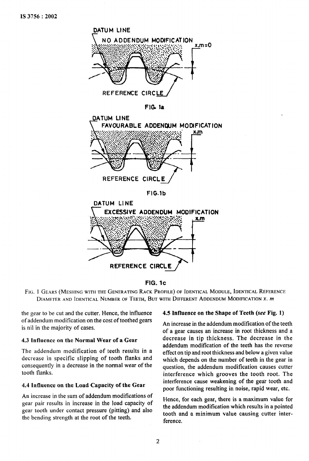
The effect of addendum modification on the tooth form
is shown in Fig. 1. The load carrying capacity of the
teeth without addendum modification as shown in
Fig. 1a may be improved by the positive addendum
modification as shown in Fig. 1b. An extremely large
addendum modification results in an undesirable tooth
form with pointed teeth as shown in Fig. 1c.
The teeth with different addendum modifications
for 20° pressure angle are shown in Fig. 2.
The addendum modification coefficient x is the
addendum modification divided by the module, Thus,
the amount of addendum modification equals to x.
m.
4 IMPORTANCE OF ADDENDUM MODI-
FICATION OF THE TEETH
4.1
The addendum modification gear teeth is carried
out in order to avoid undercut, improve strength and
running properties or to adjust the centre distance.
The addendum modification is generally recom-
mended in the following cases:
a) of gears with critical number of teeth;
b) of non-standard centre distance;
c) to obtain balanced strength; and
d) to obtain reduction in sizes.
However, load capacity and running equalities do not
attain optimum values, but the gear pairs of this system
have essentially better equalities than X-2000 gear
pairs.
4.2
Cost of Manufacture of Gear Pair
.
The
value of addendum modification of teeth depends
solely, during manufacture, on the relative position of
i?
.,
. .
w
. ... ...
..
..
.<.
,, ,.
.;. .
1’-:
IS 3756:2002
DATUM LINE
r
NO ADDENDUM MODIFICATION
REFERENCE CIRC~
FIG la
DATUM LINE
~ FAVORABLE ADDENWM MOOFICATION
~. ..... ........
..,.,O., . .
. . . . . . .
. . . . . . . . . . . . . . . . .
. . . . . . ..”
... ........... ... ... .%,. . ., . .
,e..,.
. . . . . . . .. . . . . . . . ..-. .
. .. . . . . .
:9,*.:.:+ .*.:.;
X.rn
...... ... .. ..
.... . ........ .. ..
V’f+
.....,,+y,.-.+..
+...4c .,...,. :... .,
. ..
“w:::? :?.;+:.... :. .
. . /.; . ...+
●, .:..: .
. . . .... . ........................... . . .
), . . . .. . . . . . . . .
+../ . .. . . . ,., . .
. . . J :.. ::.yf.:.
. .
.A. . . . . ..
:.. ..,., . ..
:.>y,fl,... .:. ..
.:.> . .. . . .. .%..
-. ;*...,..:.../.:
. .. . . ...%.... - .%.
.,&.. / . -
.:.. ,.:..
$
~,o..:.,
— .
..””-.
.+ .
..$ ;:..;.
.%”.,. -
..<:,,
.,
REFERENCE CIRCL~
FIG.lb
DATUM LINE
EXCESSIVE ADDENDIJM MODIFICATION
—.
REFERENCE CIRCLE
FIG. lC
Fl~. 1 GEARS (MESHING WITH THE GENERATING RACK PROFILE) OF IDENTICAL MODULE, IDENTICAL REFERENCE
DIAMETER AND IDENTICAL NUMBER OF TEETH, BUT WITH DIFFERENTADDENDUM MODIFICATION x. m
the gear to be cut and the cutter, Hence, the influence
of addendum modification on the cost of toothed gears
is nil in the majority of cases.
4.3 Influence
on the Normal Wear of a Gear
The addendum modification of teeth results in a
decrease in specific slipping of tooth flanks and
consequent] y in a decrease in the normal wear of the
tooth flanks.
4.4
Influence on the Load Capacity of the Gear
An increase in the sum of addendum modifications of
gear pair results in increase in the load capacity of
gear tooth under contact pressure (pitting) and also
the bending strength at the root of the teeth.
4.5
Influence on the Shape of Teeth (see Fig. 1)
An increase in the addendum modification of the teeth
of a gear causes an increase in root thickness and a
decrease in tip thickness. The decrease in the
addendum modification of the teeth has the reverse
effect on tip and root thickness and below a given value
which depends on the number of teeth in the gear in
question, the addendum modification causes cutter
interference which grooves the tooth root. The
interference cause weakening of the geir tooth and
poor functioning resulting in noise, rapid wear, etc.
Hence, for each gear, there is a maximum value for
the addendum modification which results in a pointed
tooth and a minimum value causing cutter inter-
ference.
2
I

IS 3756:2002
ADDENDUM MODIFICATION COEFFICIENT
2=12
Z=14
2=17
Z=20
2=25
2=35
2=50
2=100
-0.6
-0.3
Q
Q
A
n
n
n
n
L
o
n
n
n
n
n
n
L
+0.3
n
n
n
n
+0.6
n
FtG. 2 EFFECT OF THE NUMBER OF TEETH AND THE ADDENDUM MODIFICATION COEFFICIENTx
ON THE TOOTH FORM FOR (x =
20°, h,P= 1.0 m, h~P= 1.25 m
4.6 Influence
on Contact
An increase in the addendum modification of the teeth
of the mating gears causes a slight decrease in the
contact ratio of the gear pair. Hence, it is necessary to
take into account while selecting the addendum
modifications for high speed gear pairs to avoid speed
irregularity and increase in the level of vibrations.
4.7
Influence on the Clearance at the Root of Teeth
Increase in the sum of the addendum modification in
conjunction with small number of teeth in the gear
pair may cause excessive increase in the bottom
clearance resulting in detrimental phenomena, such
as interference, lubricant pressure, etc.
4.8
Speed Reducing and Speed Increasing Gear
Pairs
By considering the kinematics of a gear pair, it is
ascertained that the slipping of the loading tooth
during approach time, is in the opposite direction to
the movement of the point of contact on the tooth flank.
This results in ajamming effect which interferes with
correct operation of the gear. A favorable solution is
to reduce the approach time by giving the leading tooth
as large an addendum modification as possible. For a
given sum of addendum modifications, as small an
addendum modification as possible shall be chosen
for the driven gear.
For a speed reducing gear pair, the pinion is driving
and it is preferable to increase the addendum modi-
fication of the pinion when the accompanying
reduction is the addendum modification of the gear
has no detrimental effect.
For a speed increasing gear pair, the gear is driving
and in this case, a reduction in the addendum
modification of the driven pinion is detrimental to the
gear pair, if it becomes too great. To obtain a suitable
speed increasing gear pair, an addendum modification
3

IS 3756:2002
smaller than in the case of speed reducing gear pair
shall be chosen without however going to an
unacceptable value.
5 SUM OF ADDENDUM MODIFICATION
COEFFICIENTS
5.1 Virtual Number
of Teeth (z,)
To include straight teeth and helical teeth in the
identical formulae, the virtual number of teeth defined
by the following equation is used:
[
z
~=
COS2fib Cos p
1
sinpA= sin~. cosa
5.2 General
The choice of sum of addendum modification
coefficients, Z2 is arbitrary and depends on the centre
distance variation of operating conditions desired. Too
high or too low value of ,Zkmay be harmful to the
satisfactory functioning of the gear pair. Therefore,
in this standard, conventional and recommended upper
and lower limits are specified for Lk.
5.3
Conventional Limits
The following equations define the conventional limits
for .ZXwhich shall not be exceeded under any
circumstances. Figure 3 is the graphical representation
FIG.
1.6
1.4
1.2
1.(J
0.8
0,6
0..4
042
0
-0.2
–0.4
-0.6
of these limits. The shaded parts of Fig. 3 indicate the
zones for special cases and the verification of the
operating conditions is essential if Zk is chosen from
these shaded areas.
5.3.1
Upper Conventional Limit for .?3
For 205 Z2V<80, a= (loo+ .2,)/120
For 80< .ZzV,
h= 1.5
5.3.2
Lower Conventional Limit for .Xx
For 20<2, S 40,
x = 0.0375 (40-2,)
For 40< .XzVS 160,
a = 0.005 (40-Xzv)
For 160 <22,.
,Z!t= – 0.60
5.4
Recommended Limits
The following equations define the recommended
limits for the sum of addendum modification
coefficients, within which there is no risk of any faulty
operation and consequently no need for any type of
verification. Figure 3 also gives the graphical represen-
tation of recommended limits for .Zx.
5.4.1
Upper Recommended Limit for .23
For 20s Zzv,
a=
1.0
5.4.2 Lower Recommended Limit for .23
For 20< .22,s 60,
,2X= 0.025 (60 - .ZzV)
For 60<22,,
a =
0.0
The sum of the number of teeth (normal or virtual) of
?
L
7
1~~
I
I
I I
L
—-
20 40 60
80
100
120
140 160
Zy
3 COFIVENTIONALAND RECOMMENDED LIMITS FOR THE SUM OF THE ADDENDUM MODIFICATION COEFFICIENTS
AND ZONES FOR SPECIAL CASES
4
IS 3756:2002
the gear pair sha]] in no case be less than 20 for
addendum modification. Recommended sum of
number of teeth is 24,
5.5 Selection of the Sum of Addendum Modification
Coefficients
The choice of the sum of addendum modification
coefficients shall be made taking into account the
following:
a) For any increase in the sum of addendum
modification coefficients, there is a corres-
ponding increase in the breaking load capa-
city.
b) For any reduction in the sdm of addendum
modification coefficients, there is a
corres-
ponding increase in the contact ratio.
5.5.1
Rekuion Be[ween Centre Dis(ance, Sum of the
Addendum A40d(fication Coefficients and the
Operuling Pressure Angle
.
These relations are expressed as follows:
--
In
= (z, + z2)/2.0
d,” =
(d, + cQ/2.O
The following values are recommended for k:
0.5 < k 50.75,
for speed reducing gears
o <A SO.5,
for speed increasing gears
For the gears with gear ratio exceeding 5, the
distribution of sum of the addey~p+2Xndum modification
coefficients is calculated with u = 5.
However, the final choice of addendum modification
coefficients, xl and X2shall be done within the limits
specified at 7.
7
LIMITING VALUES OF THE ADDENDUM
MODIFICATION COEFFICIENT
Too small an addendum modification coefficient gives
rise to cutter interference and too large an addendum
modification coefficient produces a pointed tooth. The
exact values producing either cutter interference or
pointed tooth for given virtual number of teeth are the
lower and upper geometric limits respectively. The
conventional and recommended limits are given
below:
7.1
Conventional Limits
7.1,1 Upper Conventional Limil
tan cf = tan a Ices ~
For6 <z, < 10,
X = 0.60
a cos a;
= dl~. cos at
ForlO<zv <50,
x = ‘0.50+ 0.01 z
v
xx
== Z,n
(inv a:– inv a,)/tan a For 50< z,,
x= 1.0
inv
at
=
tan a, – a,. 7r/180
7.1.2
Lower Conventional Limit
inv a’,
= tan a;– a;.
rd180
For6<zv <12,
X = 0.05 (18.0 –Zv)
6 DISTRIBUTION OF SUM OF ADDENDUM
For 12 <z, <20,
x = 0.0375 (20.0 – z,)
MODIFICATION COEFFICIENTS ON THE
TWO MATING GEARS
For the distribution of the sum of addendum
modification coefficients, Xxon the two mating gears,
it is recommended to use the following formulae:
Addendum modification coefficient of the pinion:
For the straight teeth, P= Oand z, = z and where the
number of teeth of the two mating gears appear by
their ratio.
+=4-1+x{*I
For 20 <z, < 50,
X = (20.0 – 2,)/60.0
For 50< Zv,
x = – 0.50
The graphical representation of conventional limits
are given in Fig. 4.
7.2
Recommended Limits
7.2.1 Upper Recommended Limit
For 6 s Zv,
X = 0.60
7.2.2
Lower Recommended Limit
For 6< z,s 50,
X = 0.025 (30.0 – Z,)
For 50< z,,
X=– O.50 -
The graphical representation of recommended limits
are given in Fig. 4. The virtual number of teeth of a
gear-shall alwa~s have 6 as its lower limit. The shaded
‘=’[s;+
‘[+
portions of Fig. 4 represent the zones in which the
choice of addendum modification coefficient
necessitates verification of the characteristics of the
X2=.X-X1
gear pair.
5

IS 3756:2002
1.0
0.8
0.6
O-L
0.2
0
– 0.2
–0.4
– 0.6
x
I
.. .
LIMIT
I
I
If the selected addendum modification coefficient is
within the recommended limits as given in Fig. 4, h
is not necessary to verify the operating characteristics
of the gear pair.
7.3
Tip Thickness
The Fig,’5 gives the curves for constant tip thickness
equal to O, 0.1
m,, 0.2 m., 0.3 m., and 0.4 m. for a
tooth depth in conformity with basic rack tooth profile
without any reduction in the addendum.
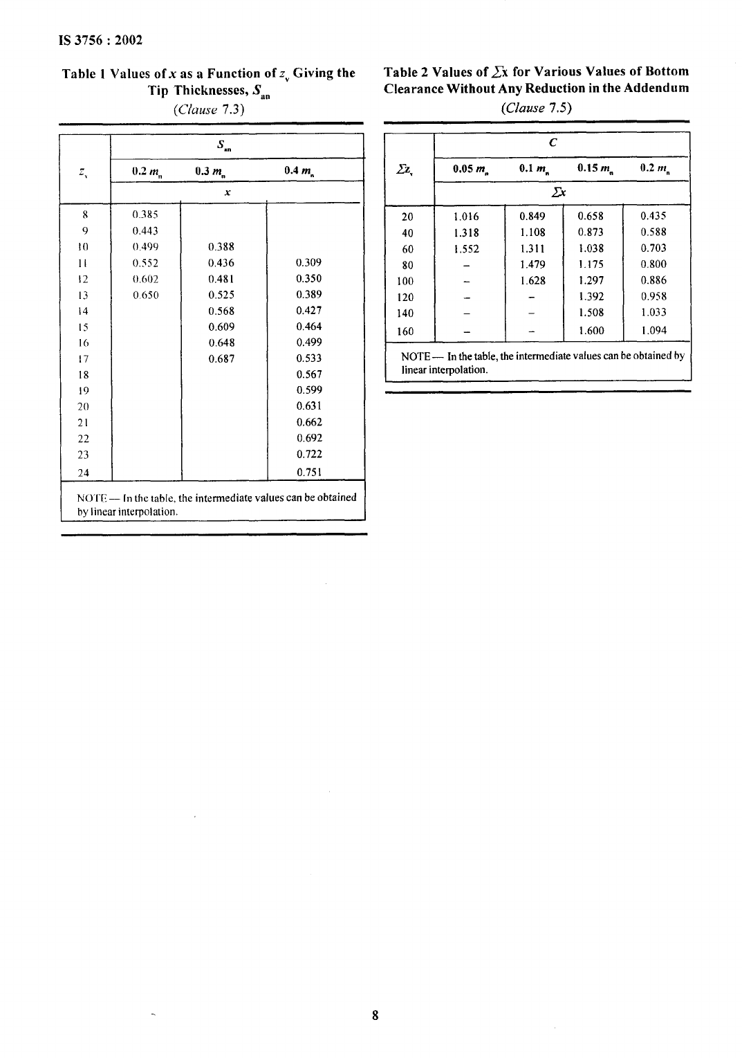
Table 1 gives the values of addendum modification
coefficient as a function of virtual number of teeth
relating to these curves.
7.4
Reduction of the Addendum of Teeth
If it is desired to retain a tip thickness greater than
0.2 m,,, in some cases, it is useful to reduce the
6
addendum of the teeth. Reduction in addendum,
‘k
can be calculated using the following formulae:
For x <0.6,
k = 0.01 (50.0x – 3.0 Zv + 6.0)
For x >0.6,
k = 0.01 (70.0X -3.0 Zv - 6.0)
[
~+2.o(l.o+x–k
where
da = m. ~os~
1
If k is calculated as negative, k = 0,
7.5 Values of Bottom Clearance
The sum of addendum modification coefficients of a
gear pair has an effect on the value of bottom clearance.
Figure 6 gives the curves representing .22xas a function
of ZzV,the constant clearance for a given curve and
taking respectively the five values :0.05
mn, 0.1 mn,
0.15 m.,
0.2 mn and 0.25 mn. Table 2 gives some values
relating to these curves.
—
Zy
I
I
I 1
I
I
I
, 1 i 1 1 1
I w
I
1
I
I i I I
—
I I
I
10
20
30
40 50 60 70
FIG. 4 CONVENTIONAL Afi~ RECOMMENDED LIMITS FOR THE ADDENDUM
MODIFICATION AND ZONES FOR SPECIAL CASES
I

IS 3756:2002
1.2
1.0
0.8
0.6
0.4
0.2
0
-0.2
2&6
8 10 12 14
16 18 20 22 24 26 28 30 32 34
1.6
1.4
1.2
1.0
0.8
0.6
0.4
0.2
0
-o-2
-o.&
-0.6
(NOTE — Line k = Oismerged with S8n= 0.2 mn)
FIG. 5 CONSTANT TIP THICKNESSES
20
40 60 80
100 120
140 160
FIG.
6 CONSTANT BOTTOM CLEARANCES
7
\
IS 3756:2002
Tablel Values ofxasa Function ofz, Giving the
Table 2
Values of Zx for Various Values of Bottom
i
Tip Thicknesses, S,n
Clearance Without Any Reduction in the Addendum
f
(Cfuuse 7.3)
(Clause 7.5)
p
s
“n
~.
().2 m. 0.3 m.
0.4 mn
x
8
0.385
9 0.443
10 0.499 0.388
II
0.552 0.436 0.309
12
().602
0.481 0,350
13 0650
0.525 0.389
14 0,568 0.427
Is
0.609 0.464
16
0.648 0.499
[7 0.687 0.533
18 0.567
19
0.599
20
0.631
21 0.662
22
0.692
23 0.722
24 0.751
NO’l”E— [n thetable, the intermediate values canbeobtained
by linear interpolation.
c
12,
0.05 mn
0.1 mn
0.15 mn
0.2
mn
23
20
1.016
0.849
0.658 0.435
40 1.318
1.108
0.873
0.588
60 1,552
1.311 1.038 0.703
80
—
1.479
1.175
0.800
100
—
1.628
1.297 0.886
120
—
1.392
0.958
140
—
—
1.508 1.033
160
—
1.600
1.094
NOTE — In thetable,theintermediatevaluescanbeobtainedby
linearinterpolation.
I

Bureau of Indian Standards
BIS is a statutory institution established under the Bureau OJ Indian Standards Act, 1986 to promote
harmonious development of the activities of standardization, marking and quality certification of goods
and attending to connected matters in the country.
Copyright
BIS has the copyright of all its publications. No part of these publications may be reproduced in any form
without the prior permission in writing of BIS. This does not preclude the free use, in the course of
implementing the standard, of necessary details, such as symbols and sizes, type or grade designations.
Enquiries relating tg copyright be addressed to the Director (Publications), BIS.
Review of Indian Standards
Amendments are issued to standards as the need arises on the basis of comments. Standards are also reviewed
periodically; a standard along with amendments is reaffirmed when such review indicates that no changes are
needed; if the review indicates that changes are needed, it is taken up for revision. Users of Indian Standards
should ascertain that they are in possession of the latest amendments or edition by referring to the latest issue of
‘BIS Catalogue’ and ‘Standards: Monthly Additions’.
ThisIndian Standard has been developed from DOC : No. BP 13 (0036).
Amendments Issued Since Publication
Amend No.
Date of Issue
Text Affected
BUREAU OF INDIAN STANDARDS
Headquarters :
Manak Bhavan, 9 Bahadur Shah Zafar Marg, New Delhi 110002
Telegrams
: Manaksanstha
Telephones :3230131, 3233375,3239402
(Common to all offices)
Regional Offices :
Telephone
Central :
Eastern :
Northern :
Southern :
Western :
Manak Bhavan, 9 Bahadur Shah Zafar Marg
{
3237617
NEW DELHI 110002
3233841
1/14 C.I.T. Scheme VII M, V. I. P. Road, Kankurgachi
{
3378499, 3378561
KOLKATA 700054
3378626, 3379120
SCO 335-336, Sector 34-A, CHANDIGARH 160022
{
603843
602025
C.I.T. Campus, IV Cross Road, CHENNAI 600113
{
2541216, 2541442
2542519,25413 15
Manakalaya, E9 MlDC, Marol, Andheri (East)
{
8329295, 8327858
MUMBA1 400093
~ 8327891,8327892
Branches : AHMEDABAD. BANGALORE. BHOPAL. BHUBANESHWAR. COIMBATORE. FARIDABAD.
GHAZIAE3AD. GUWAHATI. HYDERABAD. JAIPUR. KANPUR. LUCKNOW. NAGPUR.
NALAGARH. PATNA. PUNE. RAJKOT. THIRUVANANTHAPURAM. VISAKHAPATNAM.
printedat F’rnbhatOffset Press, New De1h&2
...”
I
